Owners Manual
Page 8
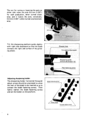
...sharpening platform guide slightly with right side downward so that the blade contacts the right side surface of the blade to be inserted so as to contact the blade fastening screws. Then lightly tighten the blade fastening screws and set the holder on either side raises the pole 0.5 mm (1/32") ...for raising or lowering the pole on the platform. - Blade I \ Forward adiurt screw I I I The sharpening holder horizontal (forward) adjust screws should be unscrewedto allow the heel of the grinding wheel. The nut for each graduation, when ...
...sharpening platform guide slightly with right side downward so that the blade contacts the right side surface of the blade to be inserted so as to contact the blade fastening screws. Then lightly tighten the blade fastening screws and set the holder on either side raises the pole 0.5 mm (1/32") ...for raising or lowering the pole on the platform. - Blade I \ Forward adiurt screw I I I The sharpening holder horizontal (forward) adjust screws should be unscrewedto allow the heel of the grinding wheel. The nut for each graduation, when ...
Owners Manual
Page 9
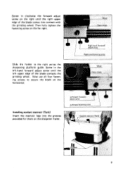
Now use all four fastening screws to the right across the sharpening platform guide. Screw in the left upper edge of the blade comes into the grooves provided for them on the sharpener frame. 9 Then fully tighten the fastening screw on the horizontal. Installingcoolant reservoir (Tank) Insert the reservoir legs into contact with the grinding wheel. Slide the holder to secure the blade on the far right. Screw in clockwise the forward adjust screw on the right until the left -hand forward adjust screw until the right upper edge of the blade contacts the grinding wheel.
Now use all four fastening screws to the right across the sharpening platform guide. Screw in the left upper edge of the blade comes into the grooves provided for them on the sharpener frame. 9 Then fully tighten the fastening screw on the horizontal. Installingcoolant reservoir (Tank) Insert the reservoir legs into contact with the grinding wheel. Slide the holder to secure the blade on the far right. Screw in clockwise the forward adjust screw on the right until the left -hand forward adjust screw until the right upper edge of the blade contacts the grinding wheel.
Owners Manual
Page 11
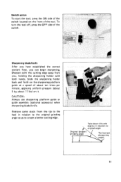
Sharpening blade/knife 1 After you have established the correct coolant flow, you , holding the sharpening holder with the cutting edge away from the tip to the heel in relation to the original grinding angle so as to create a better ...cutting edge. 1 Take down this area slightly in relation t o A o r i g i l a l angle Original (proper) grinding angle Tip (correct sharpening 11 Slide the sharpening holder back and forth on the front of the tool. CAUTION : Always use sharpening platform guide or guide assembly (optional accessory) when sharpening bladdknife. Remove some...
Sharpening blade/knife 1 After you have established the correct coolant flow, you , holding the sharpening holder with the cutting edge away from the tip to the heel in relation to the original grinding angle so as to create a better ...cutting edge. 1 Take down this area slightly in relation t o A o r i g i l a l angle Original (proper) grinding angle Tip (correct sharpening 11 Slide the sharpening holder back and forth on the front of the tool. CAUTION : Always use sharpening platform guide or guide assembly (optional accessory) when sharpening bladdknife. Remove some...
Owners Manual
Page 15
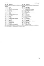
MODEL 9820.2 SDDESCRIPTION ,":,DESCRIPTION Sep-19-'84 US MACHINE MACHINE 1 1 Knob 65 2 1 Vinyl Tube 3 1 Wheel Cover 4 2 Pan Head Screw M5x20 (With Washer) 5 2 set Plate 6 2 Screw M6x31 7 1 Name ... Washer 6 Compression Spring 7 Main Pole Rail Torsion Spring 8 + Pan Head Screw M 6 Band Flat Washer 6 IhSUl.lfOn Paper Pan Head Screw M4x8 IWith Washerl Screw M6x71 Blade Holder 400 Screw M6x18 Blade Set Plate 400 Note The Switch and Other pari speclflcatlons may dlffer from country to country. 15
MODEL 9820.2 SDDESCRIPTION ,":,DESCRIPTION Sep-19-'84 US MACHINE MACHINE 1 1 Knob 65 2 1 Vinyl Tube 3 1 Wheel Cover 4 2 Pan Head Screw M5x20 (With Washer) 5 2 set Plate 6 2 Screw M6x31 7 1 Name ... Washer 6 Compression Spring 7 Main Pole Rail Torsion Spring 8 + Pan Head Screw M 6 Band Flat Washer 6 IhSUl.lfOn Paper Pan Head Screw M4x8 IWith Washerl Screw M6x71 Blade Holder 400 Screw M6x18 Blade Set Plate 400 Note The Switch and Other pari speclflcatlons may dlffer from country to country. 15


