

Owners Manual
Page 2
... your work area clean and well lit. Do not operate power tools in explosive atmospheres, such as in a polarized outlet only one blade is wider than the other.) This plug will fit in the presence of flammable liquids, gases, or dust. Double insulated tools are equipped... way. Keep bystanders, children, and visitors away while operating a power tool. SPECIFICATIONS Model Planing width Planing depth No load speed (RPM) Overall length Net weight 1912B 110 mm (4-3/8") 2 mm (1/16") 16, 000/min. 355 mm (14") 4.2 kg (9.3 lbs) • Manufacturer reserves the right to change the plug ...
... your work area clean and well lit. Do not operate power tools in explosive atmospheres, such as in a polarized outlet only one blade is wider than the other.) This plug will fit in the presence of flammable liquids, gases, or dust. Double insulated tools are equipped... way. Keep bystanders, children, and visitors away while operating a power tool. SPECIFICATIONS Model Planing width Planing depth No load speed (RPM) Overall length Net weight 1912B 110 mm (4-3/8") 2 mm (1/16") 16, 000/min. 355 mm (14") 4.2 kg (9.3 lbs) • Manufacturer reserves the right to change the plug ...

Owners Manual
Page 4
...Rags, cloth, cord, string and the like should never be performed only by unqualified personnel could indicate poor installation or a poorly balanced blade. 8. Keep hands away from repeated use) replace strict adherence to use only identical replacement parts. When using the tool on cord length...Not Recommended SPECIFIC SAFETY RULES USB042-2 DO NOT let comfort or familiarity with both hands. 6. Avoid cutting nails. Be sure the blade installation bolts are securely tightened before the switch is in a risk of electric shock or injury. Follow instructions in doubt, use ...
...Rags, cloth, cord, string and the like should never be performed only by unqualified personnel could indicate poor installation or a poorly balanced blade. 8. Keep hands away from repeated use) replace strict adherence to use only identical replacement parts. When using the tool on cord length...Not Recommended SPECIFIC SAFETY RULES USB042-2 DO NOT let comfort or familiarity with both hands. 6. Avoid cutting nails. Be sure the blade installation bolts are securely tightened before the switch is in a risk of electric shock or injury. Follow instructions in doubt, use ...
Owners Manual
Page 5
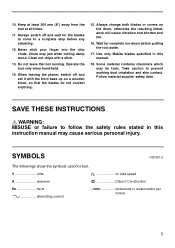
... the safety rules stated in this instruction manual may cause serious personal injury. SYMBOLS USD201-2 The followings show the symbols used for the blades to come to a complete stop before putting the tool aside. 17. When leaving the planer, switch off and wait for tool. ...held. 14. SAVE THESE INSTRUCTIONS WARNING: MISUSE or failure to prevent working dust inhalation and skin contact. Follow material supplier safety data. Use only Makita blades specified in this manual. 18. Do not leave the tool running. Never stick your finger into the chip chute. V volts A amperes n ...
... the safety rules stated in this instruction manual may cause serious personal injury. SYMBOLS USD201-2 The followings show the symbols used for the blades to come to a complete stop before putting the tool aside. 17. When leaving the planer, switch off and wait for tool. ...held. 14. SAVE THESE INSTRUCTIONS WARNING: MISUSE or failure to prevent working dust inhalation and skin contact. Follow material supplier safety data. Use only Makita blades specified in this manual. 18. Do not leave the tool running. Never stick your finger into the chip chute. V volts A amperes n ...
Owners Manual
Page 6
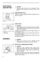
... be sure that the tool is switched off together with the socket wrench. Socket wrench 6 001605 Removing or installing planer blades 1 CAUTION: • Tighten the blade installation bolts carefully when attaching the blades to stop the tool from the locked position, pull the switch trigger fully, then release it. A loose installation bolt can... trigger. For continuous operation, pull the switch trigger and then push in the tool, always check to see they are tightened securely. To remove the blades on the drum, unscrew the installation bolts with the...
... be sure that the tool is switched off together with the socket wrench. Socket wrench 6 001605 Removing or installing planer blades 1 CAUTION: • Tighten the blade installation bolts carefully when attaching the blades to stop the tool from the locked position, pull the switch trigger fully, then release it. A loose installation bolt can... trigger. For continuous operation, pull the switch trigger and then push in the tool, always check to see they are tightened securely. To remove the blades on the drum, unscrew the installation bolts with the...
Owners Manual
Page 7
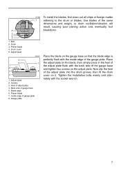
... plate 8. Tighten the installation bolts evenly and alternately with the inside edge of the gauge plate. Drum 3. Drum cover 5. Place the blade on the blade, then simply press in the heel of the adjust plate flush with the back side of adjust plate 4. Place the adjust plate on ...Heel of the gauge base and tighten two screws on it. Planer blade 7. Adjust plate 2. Gauge plate To install the blades, first clean out all chips or foreign matter adhering to the drum or blades. Now slip the heel of gauge base 5. Blade edge 6. Bolt 2. Screws 3. Back side of the adjust plate ...
... plate 8. Tighten the installation bolts evenly and alternately with the inside edge of the gauge plate. Drum 3. Drum cover 5. Place the blade on the blade, then simply press in the heel of the adjust plate flush with the back side of adjust plate 4. Place the adjust plate on ...Heel of the gauge base and tighten two screws on it. Planer blade 7. Adjust plate 2. Gauge plate To install the blades, first clean out all chips or foreign matter adhering to the drum or blades. Now slip the heel of gauge base 5. Blade edge 6. Bolt 2. Screws 3. Back side of the adjust plate ...
Owners Manual
Page 8
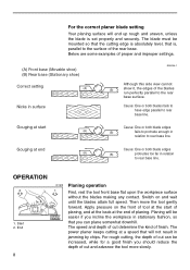
... depth of planing. Gouging at start of planing, and at the back at end Cause: One or both blades fails to have edge parallel to rear base line. Then move the tool gently forward. The blade must be easier if you should reduce the depth of cut determine the kind of the... perfectly parallel to rear base line. End 8 001608 1 Planing operation First, rest the tool front base flat upon the workpiece surface without the blades making any contact. Planing will not result in stationary fashion, so that you can be increased, while for a good finish you incline the workpiece in ...
... depth of planing. Gouging at start of planing, and at the back at end Cause: One or both blades fails to have edge parallel to rear base line. Then move the tool gently forward. The blade must be easier if you should reduce the depth of cut determine the kind of the... perfectly parallel to rear base line. End 8 001608 1 Planing operation First, rest the tool front base flat upon the workpiece surface without the blades making any contact. Planing will not result in stationary fashion, so that you can be increased, while for a good finish you incline the workpiece in ...
Owners Manual
Page 9
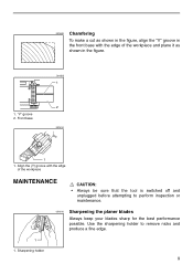
... and unplugged before attempting to remove nicks and produce a fine edge. 1 1. Use the sharpening holder to perform inspection or maintenance. 001610 Sharpening the planer blades Always keep your blades sharp for the best performance possible. Front base 001613 1 2 001614 1 1. Sharpening holder 9 "V" groove 2. 001609 Chamfering To make a cut as shown in the figure...
... and unplugged before attempting to remove nicks and produce a fine edge. 1 1. Use the sharpening holder to perform inspection or maintenance. 001610 Sharpening the planer blades Always keep your blades sharp for the best performance possible. Front base 001613 1 2 001614 1 1. Sharpening holder 9 "V" groove 2. 001609 Chamfering To make a cut as shown in the figure...
Owners Manual
Page 10
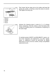
... wing nuts on the holder and insert the blades (A) and (B), so that the blades both contact the dressing stone for 2 or 3 minutes before sharpening. To maintain product SAFETY and RELIABILITY, repairs, carbon brush inspection and replacement, any other maintenance or adjustment should be performed by Makita Authorized or Factory Service Centers, always using...
... wing nuts on the holder and insert the blades (A) and (B), so that the blades both contact the dressing stone for 2 or 3 minutes before sharpening. To maintain product SAFETY and RELIABILITY, repairs, carbon brush inspection and replacement, any other maintenance or adjustment should be performed by Makita Authorized or Factory Service Centers, always using...

Owners Manual
Page 11
...need any other accessories or attachments might present a risk of any assistance for more details regarding these accessories, ask your Makita tool specified in this manual. The use accessory or attachment for its stated purpose. Only use of injury to persons.... ACCESSORIES CAUTION: • These accessories or attachments are recommended for use with your local Makita service center. • 110 mm (4-3/8") Planer blade • Dressing stone • Sharpening holder assembly • Blade gauge • Guide rule • Extension guide set • Socket wrench 9 •...
...need any other accessories or attachments might present a risk of any assistance for more details regarding these accessories, ask your Makita tool specified in this manual. The use accessory or attachment for its stated purpose. Only use of injury to persons.... ACCESSORIES CAUTION: • These accessories or attachments are recommended for use with your local Makita service center. • 110 mm (4-3/8") Planer blade • Dressing stone • Sharpening holder assembly • Blade gauge • Guide rule • Extension guide set • Socket wrench 9 •...

Parts Breakdown
Page 2
... Name POWER SUPPLY CORD, JN1601 CORD (2X18X8 SJT), 3621 SWITCH,JN3200 HANDLE COVER, 1912B P.H. SCREW M5X18, GA7911 P.H. SCREW M5X65, GA7911 P.H. SCREW M4X14, N9501B V-PULLEY 4-38, 1912B B. BOLT M6X17, 2030S FLAT WASHER 5, 1912B SHARPENING HOLDER ASSY, 1912B SOCKET WRENCH, 4200H 4-3/8HSS PLANER BLADE,1912B BLADE GAUGE, 1902 Page 2 of 3 Quantity 1 1 1 1 3 1 1 1 4 2 1 1 1 2 1 1 1 1 1 1 1 1 1 6 6 1 1 1 1 1 1 1 2 2 2 1 1 1 1 1 1 6 1 1 1 1 1 1 1 1 1 1 1 1 2 4 1 1 8 2 1 1 1 1 8/18/2010 SCREW M4X28, JR3000V P.H. WASHER, JN3200 ARMATURE...
... Name POWER SUPPLY CORD, JN1601 CORD (2X18X8 SJT), 3621 SWITCH,JN3200 HANDLE COVER, 1912B P.H. SCREW M5X18, GA7911 P.H. SCREW M5X65, GA7911 P.H. SCREW M4X14, N9501B V-PULLEY 4-38, 1912B B. BOLT M6X17, 2030S FLAT WASHER 5, 1912B SHARPENING HOLDER ASSY, 1912B SOCKET WRENCH, 4200H 4-3/8HSS PLANER BLADE,1912B BLADE GAUGE, 1902 Page 2 of 3 Quantity 1 1 1 1 3 1 1 1 4 2 1 1 1 2 1 1 1 1 1 1 1 1 1 6 6 1 1 1 1 1 1 1 2 2 2 1 1 1 1 1 1 6 1 1 1 1 1 1 1 1 1 1 1 1 2 4 1 1 8 2 1 1 1 1 8/18/2010 SCREW M4X28, JR3000V P.H. WASHER, JN3200 ARMATURE...


