Owners Manual
Page 1
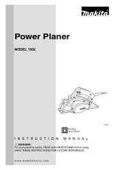
SAVE THESE INSTRUCTIONS FOR FUTURE REFERENCE. Power Planer MODEL 1902 DOUBLE INSULATION 002543 INSTRUCTION MANUAL WARNING: For your personal safety, READ and UNDERSTAND before using. www.makitatools.com
SAVE THESE INSTRUCTIONS FOR FUTURE REFERENCE. Power Planer MODEL 1902 DOUBLE INSULATION 002543 INSTRUCTION MANUAL WARNING: For your personal safety, READ and UNDERSTAND before using. www.makitatools.com
Owners Manual
Page 4
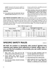
... smaller the gage number, the heavier the cord. When servicing a tool, use the next heavier gage. If in loss of unauthorized parts or failure to planer safety rules. Inspect for and remove all nails from rotating parts. 7.
... smaller the gage number, the heavier the cord. When servicing a tool, use the next heavier gage. If in loss of unauthorized parts or failure to planer safety rules. Inspect for and remove all nails from rotating parts. 7.
Owners Manual
Page 5
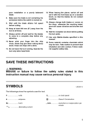
... contains chemicals which may jam when cutting damp wood. Chute may be toxic. Always change both blades or covers on . 9. Use only Makita blades specified in this manual. 18. SAVE THESE INSTRUCTIONS WARNING: MISUSE or failure to prevent dust inhalation and skin contact. Wait until the ...Make sure the blade is turned on the drum, otherwise the resulting imbalance will cause vibration and shorten tool life. 16. When leaving the planer, switch off and wait for the blades to come to a complete stop before cutting. 10. SYMBOLS USD201-2 The followings show the symbols...
... contains chemicals which may jam when cutting damp wood. Chute may be toxic. Always change both blades or covers on . 9. Use only Makita blades specified in this manual. 18. SAVE THESE INSTRUCTIONS WARNING: MISUSE or failure to prevent dust inhalation and skin contact. Wait until the ...Make sure the blade is turned on the drum, otherwise the resulting imbalance will cause vibration and shorten tool life. 16. When leaving the planer, switch off and wait for the blades to come to a complete stop before cutting. 10. SYMBOLS USD201-2 The followings show the symbols...
Owners Manual
Page 6
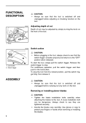
...; Before plugging in the lock button. Release the switch trigger to see they are tightened securely. • Handle the blades very carefully. Removing or installing planer blades CAUTION: • Tighten the blade installation bolts carefully when attaching the blades to protect your fingers or hands when removing or installing the blades...
...; Before plugging in the lock button. Release the switch trigger to see they are tightened securely. • Handle the blades very carefully. Removing or installing planer blades CAUTION: • Tighten the blade installation bolts carefully when attaching the blades to protect your fingers or hands when removing or installing the blades...
Owners Manual
Page 7
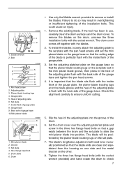
...installation bolts. Groove 3. The blade's lengthwise adjustment will be manually positioned so that a gap exists between the drum and the set the mini planer blade on the drum, unscrew the three installation bolts with the blades. 2. Set plate 7. Remove the existing blade, if the tool has been...drum surfaces and the drum cover. Socket wrench 2. Drum • Use only the Makita wrench provided to ensure uniform cutting. 5. The blade will need to check 7 Heel of the gauge plate, the planer blade locating lugs sit in the three hex flange head bolts so that the blade ...
...installation bolts. Groove 3. The blade's lengthwise adjustment will be manually positioned so that a gap exists between the drum and the set the mini planer blade on the drum, unscrew the three installation bolts with the blades. 2. Set plate 7. Remove the existing blade, if the tool has been...drum surfaces and the drum cover. Socket wrench 2. Drum • Use only the Makita wrench provided to ensure uniform cutting. 5. The blade will need to check 7 Heel of the gauge plate, the planer blade locating lugs sit in the three hex flange head bolts so that the blade ...
Owners Manual
Page 8
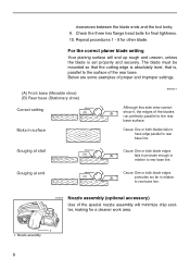
... of proper and improper settings. (A) Front base (Movable shoe) (B) Rear base (Stationary shoe) Correct setting (A) Nicks in relation to rear base line. For the correct planer blade setting Your planing surface will end up rough and uneven, unless the blade is , parallel to the surface of the special nozzle assembly will...
... of proper and improper settings. (A) Front base (Movable shoe) (B) Rear base (Stationary shoe) Correct setting (A) Nicks in relation to rear base line. For the correct planer blade setting Your planing surface will end up rough and uneven, unless the blade is , parallel to the surface of the special nozzle assembly will...
Owners Manual
Page 9
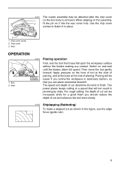
... plane somewhat downhill. End 2. Switch on the tool body is removed. The speed and depth of cut as shown in jamming by chips. The power planer keeps cutting at the end of finish.
... plane somewhat downhill. End 2. Switch on the tool body is removed. The speed and depth of cut as shown in jamming by chips. The power planer keeps cutting at the end of finish.
Owners Manual
Page 12
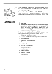
... to remove the brush holder caps. Screwdriver 002598 1 2 Use a screwdriver to persons. The use with your local Makita service center. • High-speed steel Planer blade • Tungsten-carbide Planer blade (For longer blade life) • Mini planer blade • Sharpening holder assembly • Blade gauge • Set plate set • Edge fence (Guide...
... to remove the brush holder caps. Screwdriver 002598 1 2 Use a screwdriver to persons. The use with your local Makita service center. • High-speed steel Planer blade • Tungsten-carbide Planer blade (For longer blade life) • Mini planer blade • Sharpening holder assembly • Blade gauge • Set plate set • Edge fence (Guide...
