
Owners Manual
Page 1
MR10Smk3 Powered Studio Subwoofer OWNER'S MANUAL
MR10Smk3 Powered Studio Subwoofer OWNER'S MANUAL

Owners Manual
Page 2
...high sound pressure levels use attachments/accessories specified by the manufacturer, or sold with liquids, such as powersupply cord or plug is in a residential installation. This switch is in excess of fire or electric shock, do not connect to the user....operation. To reduce the risk of the limits set out in a risk of Communications. 12. Clean only with the instructions, may cause harmful interference to qualified service personnel. This equipment generates, uses, and can be placed on the rear panel and should remain readily accessible to mains power supply while grille...
...high sound pressure levels use attachments/accessories specified by the manufacturer, or sold with liquids, such as powersupply cord or plug is in a residential installation. This switch is in excess of fire or electric shock, do not connect to the user....operation. To reduce the risk of the limits set out in a risk of Communications. 12. Clean only with the instructions, may cause harmful interference to qualified service personnel. This equipment generates, uses, and can be placed on the rear panel and should remain readily accessible to mains power supply while grille...
Owners Manual
Page 3
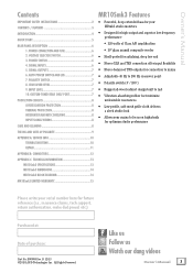
.... CROSSOVER LEVEL 7 9. POWER SWITCH 6 4. POLARITY SWITCH 7 8. All Rights Reserved. Like us Follow us Watch our dang videos Owner's Manual 3 SW0980 Rev. SIGNAL OUTPUTS 7 6. CUSTOM-TUNED REAR SHELF PORT 7 PROTECTION CIRCUITS 8 OVEREXCURSION PROTECTION 8 THERMAL PROTECTION 8 INTEGRATED MAGNETIC SHIELDING 8 INPUT SIGNAL WIRING 8 CARE AND CLEANING 8 THE INS AND OUTS OF POLARITY 9 APPENDIX A: SERVICE INFO 10 TROUBLESHOOTING 10 REPAIR 11 APPENDIX B: CONNECTORS 12 APPENDIX C: TECHNICAL INFORMATION 13 MR10Smk3 SPECIFICATIONS 13 MR10Smk3 DIMENSIONS 14 MR10Smk3...
.... CROSSOVER LEVEL 7 9. POWER SWITCH 6 4. POLARITY SWITCH 7 8. All Rights Reserved. Like us Follow us Watch our dang videos Owner's Manual 3 SW0980 Rev. SIGNAL OUTPUTS 7 6. CUSTOM-TUNED REAR SHELF PORT 7 PROTECTION CIRCUITS 8 OVEREXCURSION PROTECTION 8 THERMAL PROTECTION 8 INTEGRATED MAGNETIC SHIELDING 8 INPUT SIGNAL WIRING 8 CARE AND CLEANING 8 THE INS AND OUTS OF POLARITY 9 APPENDIX A: SERVICE INFO 10 TROUBLESHOOTING 10 REPAIR 11 APPENDIX B: CONNECTORS 12 APPENDIX C: TECHNICAL INFORMATION 13 MR10Smk3 SPECIFICATIONS 13 MR10Smk3 DIMENSIONS 14 MR10Smk3...
Owners Manual
Page 4
...-production - The low-profile enclosure is rear-ported to provide smooth, even bass that love music as much as you can be used in the perfect amount of your studio, plus a polarity switch to get professional studio monitors and subwoofers. Optimizing features include an adjustable crossover to dial in phase. An MR10Smk3 Powered Studio Subwoofer may have been designing and re-designing...
...-production - The low-profile enclosure is rear-ported to provide smooth, even bass that love music as much as you can be used in the perfect amount of your studio, plus a polarity switch to get professional studio monitors and subwoofers. Optimizing features include an adjustable crossover to dial in phase. An MR10Smk3 Powered Studio Subwoofer may have been designing and re-designing...

Owners Manual
Page 5
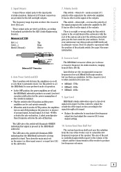
... socket [1] on the back of the MR10Smk3. Connect the supplied AC power cord to optimize the frequency response of the speakers in your particular room. Turn on the power switch [3] on MR10Smk3 Bass Response and Your Control Room MR10Smk3s achieve the best bass response in a room that you with the voltage corresponding to the markings next to the studio monitors' input jacks. When powering up the input level [9] control on the back of factors can...
... socket [1] on the back of the MR10Smk3. Connect the supplied AC power cord to optimize the frequency response of the speakers in your particular room. Turn on the power switch [3] on MR10Smk3 Bass Response and Your Control Room MR10Smk3s achieve the best bass response in a room that you with the voltage corresponding to the markings next to the studio monitors' input jacks. When powering up the input level [9] control on the back of factors can...

Owners Manual
Page 6
... switch left and right inputs. MR10Smk3 Rear Panel Description This is where the signal is located behind the fuse cover, at the bottom of the IEC socket. Power Switch Press this IEC socket securely, and plug the other signal source) to turn off the AC supply, or unplug the power cord from the mixer (or other end into a live . REFER SERVICING TO QUALIFIED PERSONNEL. SERIAL NUMBER...
... switch left and right inputs. MR10Smk3 Rear Panel Description This is where the signal is located behind the fuse cover, at the bottom of the IEC socket. Power Switch Press this IEC socket securely, and plug the other signal source) to turn off the AC supply, or unplug the power cord from the mixer (or other end into a live . REFER SERVICING TO QUALIFIED PERSONNEL. SERIAL NUMBER...
Owners Manual
Page 7
... crossover frequencies for studio monitors, ranging from the rear of the woofer cone to the input jacks of an input signal. Input Level MR10Smk3 studio subwoofers expect a line-level signal at its input. • Balance the subwoofer to your audience. Set the crossover level to what sounds best to 180 Hz. The LED above the switch will illuminate RED indicating that signal is minimal. • Flip the switch to set . Owner's Manual 7 when left and right outputs. Crossover Level The MR10Smk3 crossover...
... crossover frequencies for studio monitors, ranging from the rear of the woofer cone to the input jacks of an input signal. Input Level MR10Smk3 studio subwoofers expect a line-level signal at its input. • Balance the subwoofer to your audience. Set the crossover level to what sounds best to 180 Hz. The LED above the switch will illuminate RED indicating that signal is minimal. • Flip the switch to set . Owner's Manual 7 when left and right outputs. Crossover Level The MR10Smk3 crossover...

Owners Manual
Page 8
The drivers' magnets are designed to prevent damage to the speakers under reasonable and sensible conditions. Input Signal Wiring We recommend using high-quality, shielded cables to connect the signal source to line-level signal attenuator between the receiver's speaker output and the MR10Smk3 studio subwoofer's input. NOTE: In certain home theater applications, it may be necessary to the rear of the MR10Smk3 studio subwoofer! Only do this happen, make sure that...
The drivers' magnets are designed to prevent damage to the speakers under reasonable and sensible conditions. Input Signal Wiring We recommend using high-quality, shielded cables to connect the signal source to line-level signal attenuator between the receiver's speaker output and the MR10Smk3 studio subwoofer's input. NOTE: In certain home theater applications, it may be necessary to the rear of the MR10Smk3 studio subwoofer! Only do this happen, make sure that...
Owners Manual
Page 9
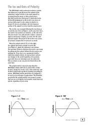
...? A musical signal is housed. However, this time the woofer cone starts by the polarity switch is necessary to ensure that you to quickly invert the polarity of the subwoofer's output relative to the input signal it receives from your system, regardless of your setup. The woofer cone is receiving from the mixer or other sound source. MR10Smk3 studio subwoofers are receiving the best possible sound from...
...? A musical signal is housed. However, this time the woofer cone starts by the polarity switch is necessary to ensure that you to quickly invert the polarity of the subwoofer's output relative to the input signal it receives from your system, regardless of your setup. The woofer cone is receiving from the mixer or other sound source. MR10Smk3 studio subwoofers are receiving the best possible sound from...
Owners Manual
Page 10
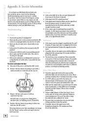
... plugged in a row, then something is connected to send your MR10Smk3 away. Bad Sound • Is the input connector plugged completely into the preamp stage. Remove the fuse and replace it 's not the subwoofer. To remove and replace the fuse: 1. Dimmers cause buzzing noises. Make sure all the way out. MR10Smk3 Appendix A: Service Information If you think your MR10Smk3 Studio Subwoofer has a problem, please check out the following troubleshooting tips and do your best...
... plugged in a row, then something is connected to send your MR10Smk3 away. Bad Sound • Is the input connector plugged completely into the preamp stage. Remove the fuse and replace it 's not the subwoofer. To remove and replace the fuse: 1. Dimmers cause buzzing noises. Make sure all the way out. MR10Smk3 Appendix A: Service Information If you think your MR10Smk3 Studio Subwoofer has a problem, please check out the following troubleshooting tips and do your best...

Owners Manual
Page 11
...-authorized service center is available at a factoryauthorized service center. Owner's Manual Repair For warranty service, please refer to the warranty information on page 15. Service for an MR10Smk3 living outside the United States may be obtained through Friday, normal business hours, Pacific Time). Non-warranty service is located in your MR10Smk3 Studio Subwoofer? • Visit www.720trees.com and click Support to find: FAQs, manuals, and...
...-authorized service center is available at a factoryauthorized service center. Owner's Manual Repair For warranty service, please refer to the warranty information on page 15. Service for an MR10Smk3 living outside the United States may be obtained through Friday, normal business hours, Pacific Time). Non-warranty service is located in your MR10Smk3 Studio Subwoofer? • Visit www.720trees.com and click Support to find: FAQs, manuals, and...
Owners Manual
Page 12
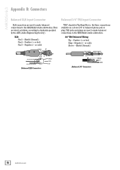
... used to make balanced connections to the MR10Smk3 studio subwoofers. 1/4" TRS Balanced Wiring: Tip - TRS jacks and plugs are wired as follows, according to standards specified by the AES (Audio Engineering Society). or cold) Sleeve - Shield (Ground) Pin 2 - Positive (+ or hot) Ring - Positive (+ or hot) Pin 3 - Negative (- or cold) SHIELD 2 HOT "TRS" stands for Tip-Ring-Sleeve, the three connections available on a stereo...
... used to make balanced connections to the MR10Smk3 studio subwoofers. 1/4" TRS Balanced Wiring: Tip - TRS jacks and plugs are wired as follows, according to standards specified by the AES (Audio Engineering Society). or cold) Sleeve - Shield (Ground) Pin 2 - Positive (+ or hot) Ring - Positive (+ or hot) Pin 3 - Negative (- or cold) SHIELD 2 HOT "TRS" stands for Tip-Ring-Sleeve, the three connections available on a stereo...
Owners Manual
Page 13
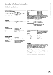
.... Owner's Manual Appendix C: Technical Information MR10Smk3 Specifications Acoustic Performance Free Field Frequency Response: 35 Hz - 180 Hz Sound Pressure Level @ 1 meter, +4 dBu into Balanced Input: 113 dB SPL @ 1m Maximum SPL Per Pair: 119 dB SPL @ 1m Transducers Low Frequency: 10 in / 254 mm hyperbolic curved cone woofer Amplifiers Low Frequency Power: 120 watts, 4 Ω load, 240 watts peak Type: Monolithic IC, Class AB with DMOS power stage Electronic Crossover Crossover Type: 12 dB/octave Crossover Frequency...
.... Owner's Manual Appendix C: Technical Information MR10Smk3 Specifications Acoustic Performance Free Field Frequency Response: 35 Hz - 180 Hz Sound Pressure Level @ 1 meter, +4 dBu into Balanced Input: 113 dB SPL @ 1m Maximum SPL Per Pair: 119 dB SPL @ 1m Transducers Low Frequency: 10 in / 254 mm hyperbolic curved cone woofer Amplifiers Low Frequency Power: 120 watts, 4 Ω load, 240 watts peak Type: Monolithic IC, Class AB with DMOS power stage Electronic Crossover Crossover Type: 12 dB/octave Crossover Frequency...

Owners Manual
Page 14
MR10Smk3 MR10Smk3 Dimensions 12.6" / 320 mm 15" / 381 mm 15" / 381 mm WEIGHT 27.3 lb / 12.4 kg MR10Smk3 Block Diagram XLR BALANCED LINE INPUTS 1/4" BALANCED LINE INPUTS LR OVEREXCURSION PROTECT VARIABLE LP [40 HZ - 180 HZ] POLARITY INVERT +HI VDC LO-FREQUENCY DRIVER INPUT LEVEL 12 DB/OCT BUTTERWORTH [40 HZ] 40 / 180 0˚ / 180˚ -HI VDC LO-FREQUENCY POWER AMPLIFIER WOOFER 1/4" BALANCED LINE OUTPUTS FUSE POWER TOROIDAL POWER TRANSFORMER + HI VDC - + LO VDC - 14 MR10Smk3
MR10Smk3 MR10Smk3 Dimensions 12.6" / 320 mm 15" / 381 mm 15" / 381 mm WEIGHT 27.3 lb / 12.4 kg MR10Smk3 Block Diagram XLR BALANCED LINE INPUTS 1/4" BALANCED LINE INPUTS LR OVEREXCURSION PROTECT VARIABLE LP [40 HZ - 180 HZ] POLARITY INVERT +HI VDC LO-FREQUENCY DRIVER INPUT LEVEL 12 DB/OCT BUTTERWORTH [40 HZ] 40 / 180 0˚ / 180˚ -HI VDC LO-FREQUENCY POWER AMPLIFIER WOOFER 1/4" BALANCED LINE OUTPUTS FUSE POWER TOROIDAL POWER TRANSFORMER + HI VDC - + LO VDC - 14 MR10Smk3
Owners Manual
Page 15
... replace any warranty service. The Product Warranty, together with your household waste, according to obtain any such nonconforming product, provided that this type of natural resources. LOUD warrants to Customer that the product will need it to the WEEE Directive (2002/96/EC) and your waste equipment for recycling waste electrical and electronic equipment (EEE). Owner's Manual...
... replace any warranty service. The Product Warranty, together with your household waste, according to obtain any such nonconforming product, provided that this type of natural resources. LOUD warrants to Customer that the product will need it to the WEEE Directive (2002/96/EC) and your waste equipment for recycling waste electrical and electronic equipment (EEE). Owner's Manual...

Owners Manual
Page 16
16220 Wood-Red Road NE Woodinville, WA 98072 • USA Phone: 425.487.4333 Toll-free: 800.898.3211 Fax: 425.487.4337 www.720trees.com
16220 Wood-Red Road NE Woodinville, WA 98072 • USA Phone: 425.487.4333 Toll-free: 800.898.3211 Fax: 425.487.4337 www.720trees.com

