User Manual
Page 11
...: Front Panel Connectors 29 JCOM1: Serial Port Connector 29 JTBT1: Thunderbolt Add-on Card Connector 29 CPU_PWR1, ATX_PWR1, PCIE_PWR1: Power Connectors 30 JUSB3~4: USB 3.1 Gen1 Connectors 31 JUSB1~2: USB 2.0 Connectors 32 JLPT1: Parallel Port Connector 32 CPU_FAN1, PUMP_FAN1, SYS_FAN1~5: Fan Connectors 33 JAUD1: Front Audio Connector 34 JCI1: Chassis Intrusion Connector 34...
...: Front Panel Connectors 29 JCOM1: Serial Port Connector 29 JTBT1: Thunderbolt Add-on Card Connector 29 CPU_PWR1, ATX_PWR1, PCIE_PWR1: Power Connectors 30 JUSB3~4: USB 3.1 Gen1 Connectors 31 JUSB1~2: USB 2.0 Connectors 32 JLPT1: Parallel Port Connector 32 CPU_FAN1, PUMP_FAN1, SYS_FAN1~5: Fan Connectors 33 JAUD1: Front Audio Connector 34 JCI1: Chassis Intrusion Connector 34...

User Manual
Page 14
... audio jacks Continued on the back panel, 4 ports available through the internal USB 2.0 connectors)* * The CNVI_1 and JUSB2 share the same bandwidth. RAID LAN USB Audio Back Panel Connectors Continued from previous page Intel® Z390 Chipset y Supports RAID 0, RAID1, RAID 5 and RAID 10 for details...devices y 1x Intel® I219-V Gigabit LAN controller y Intel® Z390 Chipset ƒ 2x USB 3.1 Gen2 (SuperSpeed USB 10Gbps) ports (1x Type-A port and 1x Type-C port) on the back panel ƒ 6x USB 3.1 Gen1 (SuperSpeed USB) ports (2 Type-A ports on the back panel, 4 ports available through...
... audio jacks Continued on the back panel, 4 ports available through the internal USB 2.0 connectors)* * The CNVI_1 and JUSB2 share the same bandwidth. RAID LAN USB Audio Back Panel Connectors Continued from previous page Intel® Z390 Chipset y Supports RAID 0, RAID1, RAID 5 and RAID 10 for details...devices y 1x Intel® I219-V Gigabit LAN controller y Intel® Z390 Chipset ƒ 2x USB 3.1 Gen2 (SuperSpeed USB 10Gbps) ports (1x Type-A port and 1x Type-C port) on the back panel ƒ 6x USB 3.1 Gen1 (SuperSpeed USB) ports (2 Type-A ports on the back panel, 4 ports available through...

User Manual
Page 15
... 12V power connector y 1x 6-pin ATX 12V power connector y 6x SATA 6Gb/s connectors y 2x M.2 slots (1 M-Key slot,1 E-Key slot) y 2x USB 3.1 Gen1 connectors (supports additional 4 USB 3.1 Gen1 ports) y 2x USB 2.0 connectors (supports additional 4 USB 2.0 ports) y 1x 4-pin CPU fan connector y 1x 4-pin Water Pump connector y 5x 4-pin system fan connectors y 1x Front panel audio...
... 12V power connector y 1x 6-pin ATX 12V power connector y 6x SATA 6Gb/s connectors y 2x M.2 slots (1 M-Key slot,1 E-Key slot) y 2x USB 3.1 Gen1 connectors (supports additional 4 USB 3.1 Gen1 ports) y 2x USB 2.0 connectors (supports additional 4 USB 2.0 ports) y 1x 4-pin CPU fan connector y 1x 4-pin Water Pump connector y 5x 4-pin system fan connectors y 1x Front panel audio...

User Manual
Page 17
Special Features Continued from previous page y Protection ƒ PCI-E Steel Armor ƒ PCI-E Steel Slot y Performance ƒ Core Boost ƒ OC Genie ƒ Multi GPU-CrossFire Technology ƒ DDR4 Boost ƒ USB with type A+C ƒ Intel Turbo USB 3.1 Gen2 y VR ƒ VR Ready y BIOS ƒ Click BIOS 5 Specifications 17
Special Features Continued from previous page y Protection ƒ PCI-E Steel Armor ƒ PCI-E Steel Slot y Performance ƒ Core Boost ƒ OC Genie ƒ Multi GPU-CrossFire Technology ƒ DDR4 Boost ƒ USB with type A+C ƒ Intel Turbo USB 3.1 Gen2 y VR ƒ VR Ready y BIOS ƒ Click BIOS 5 Specifications 17

User Manual
Page 19
Block Diagram DisplayPort VGA DVI-D 2 Channel DDR4 Memory CPU PCI Express Bus x4 DMI 3.0 PCI Express Bus 1 x M.2 Switch 6 x SATA 6Gb/s 2 x USB 3.1 Gen2 6 x USB 3.1 Gen1 6 x USB 2.0 PCI Express Bus chipset LPC Bus x1 PCIe x1 slot x1 PCIe x1 slot x1 PCIe x1 slot x1 PCIe x1 slot 1x M.2 (E Key for Intel CNVi module only) Intel I219-V NV6797 Super I/O P/S2 Mouse / Keyboard Realtek ALC892 Audio Jacks Block Diagram 19
Block Diagram DisplayPort VGA DVI-D 2 Channel DDR4 Memory CPU PCI Express Bus x4 DMI 3.0 PCI Express Bus 1 x M.2 Switch 6 x SATA 6Gb/s 2 x USB 3.1 Gen2 6 x USB 3.1 Gen1 6 x USB 2.0 PCI Express Bus chipset LPC Bus x1 PCIe x1 slot x1 PCIe x1 slot x1 PCIe x1 slot x1 PCIe x1 slot 1x M.2 (E Key for Intel CNVi module only) Intel I219-V NV6797 Super I/O P/S2 Mouse / Keyboard Realtek ALC892 Audio Jacks Block Diagram 19

User Manual
Page 20
Rear I/O Panel PS/2 VGA LAN USB 3.1 Gen2 Type-A Audio Ports DisplayPort USB 2.0 DVI-D USB 3.1 Gen2 Type-C USB 3.1 Gen1 Type-A LAN Port LED Status Table Link/ Activity LED Status Off Yellow Blinking Description No link Linked Data activity Speed LED Status Off Green ...
Rear I/O Panel PS/2 VGA LAN USB 3.1 Gen2 Type-A Audio Ports DisplayPort USB 2.0 DVI-D USB 3.1 Gen2 Type-C USB 3.1 Gen1 Type-A LAN Port LED Status Table Link/ Activity LED Status Off Yellow Blinking Description No link Linked Data activity Speed LED Status Off Green ...

User Manual
Page 24
... JLPT1 Parallel Port Connector JOC1 Front OC Button Connector JRGB1 JTBT1 JTPM1 RGB LED connector Thunderbolt Add-on Card Connector TPM Module Connector JUSB1~2 USB 2.0 Connectors JUSB3~4 USB 3.1 Gen1 Connectors M2_1 M.2 Slot (Key M) PCI_E1~6 PCIe Expansion Slots SATA1~6 SATA 6Gb/s Connectors Page 33 30 25 26 34 35 34 29 29 32...
... JLPT1 Parallel Port Connector JOC1 Front OC Button Connector JRGB1 JTBT1 JTPM1 RGB LED connector Thunderbolt Add-on Card Connector TPM Module Connector JUSB1~2 USB 2.0 Connectors JUSB3~4 USB 3.1 Gen1 Connectors M2_1 M.2 Slot (Key M) PCI_E1~6 PCIe Expansion Slots SATA1~6 SATA 6Gb/s Connectors Page 33 30 25 26 34 35 34 29 29 32...
User Manual
Page 31
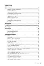
... the Power and Ground pins must be disabled. Important When the Charging mode is hardware controlled by motherboard chip, it can increase USB power output for fast charging your device in suspend, hibernate state or even shutdown states. Overview of Components 31 The Charger Port is... enabled, the Charger Port data syncing will need to install the MSI Dragon Center application to turn ON/OFF the Charging mode. JUSB3~4: USB 3.1 Gen1 Connectors These connectors allow you will be connected correctly to avoid possible damage.
... the Power and Ground pins must be disabled. Important When the Charging mode is hardware controlled by motherboard chip, it can increase USB power output for fast charging your device in suspend, hibernate state or even shutdown states. Overview of Components 31 The Charger Port is... enabled, the Charger Port data syncing will need to install the MSI Dragon Center application to turn ON/OFF the Charging mode. JUSB3~4: USB 3.1 Gen1 Connectors These connectors allow you will be connected correctly to avoid possible damage.
User Manual
Page 32
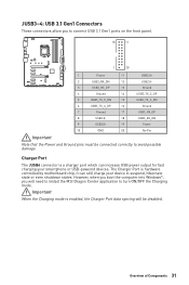
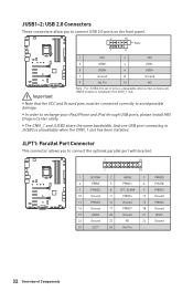
... 32 Overview of pins is unavailable when a Intel wireless-AC (CNVi) module is unavailable when the CNVI_1 slot has been installed. And one USB port connecting to connect USB 2.0 ports on the front panel. 2 10 Note 1 9 1 VCC 2 VCC 3 USB0- 4 USB1- 5 USB0+ 6 USB1+ 7 Ground 8 Ground 9 No ... y Note that the VCC and Ground pins must be connected correctly to recharge your iPad,iPhone and iPod through USB ports, please install MSI Dragon Center utility. JLPT1: Parallel Port Connector This connector allows you to JUSB2 is installed in the CNVI_1 slot.
... 32 Overview of pins is unavailable when a Intel wireless-AC (CNVi) module is unavailable when the CNVI_1 slot has been installed. And one USB port connecting to connect USB 2.0 ports on the front panel. 2 10 Note 1 9 1 VCC 2 VCC 3 USB0- 4 USB1- 5 USB0+ 6 USB1+ 7 Ground 8 Ground 9 No ... y Note that the VCC and Ground pins must be connected correctly to recharge your iPad,iPhone and iPod through USB ports, please install MSI Dragon Center utility. JLPT1: Parallel Port Connector This connector allows you to JUSB2 is installed in the CNVI_1 slot.

User Manual
Page 37
... Disc. 4. Insert MSI® Driver Disc into your computer. 3. Open the installer as described above. 2. The utilities installation will prompt you to restart. 7. Insert the Windows® 10 installation disc/USB into Boot Menu. 5. Press the Restart button on the computer. 2. Click OK button...in the Drivers/Software tab. 5. The drivers installation will prompt you must complete drivers installation. 1. Select the Windows® 10 installation disc/USB from the Boot Menu. 6. message. 7. Click the Install button in Windows® 10. 2. Installing OS, Drivers & Utilities Please ...
... Disc. 4. Insert MSI® Driver Disc into your computer. 3. Open the installer as described above. 2. The utilities installation will prompt you to restart. 7. Insert the Windows® 10 installation disc/USB into Boot Menu. 5. Press the Restart button on the computer. 2. Click OK button...in the Drivers/Software tab. 5. The drivers installation will prompt you must complete drivers installation. 1. Select the Windows® 10 installation disc/USB from the Boot Menu. 6. message. 7. Click the Install button in Windows® 10. 2. Installing OS, Drivers & Utilities Please ...

User Manual
Page 41
Important y BIOS items are for reference only and may be for BIOS item description. You could also refer to USB flash drive (FAT/ FAT32 format only). Entering BIOS Setup Please refer the following methods to avoid possible system damage or failure booting unless you purchased. ... to enter Boot Menu message appears on GO2BIOS button and choose OK. The system will reboot and enter BIOS setup directly. BIOS Setup 41 y In MSI Dragon Center application, click on the screen during the boot process. y Press Delete key, when the Press DEL key to enter Setup Menu, F11 to...
Important y BIOS items are for reference only and may be for BIOS item description. You could also refer to USB flash drive (FAT/ FAT32 format only). Entering BIOS Setup Please refer the following methods to avoid possible system damage or failure booting unless you purchased. ... to enter Boot Menu message appears on GO2BIOS button and choose OK. The system will reboot and enter BIOS setup directly. BIOS Setup 41 y In MSI Dragon Center application, click on the screen during the boot process. y Press Delete key, when the Press DEL key to enter Setup Menu, F11 to...
User Manual
Page 42
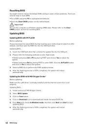
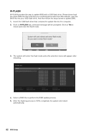
...download the latest BIOS file that contains the update file into the USB flash drive. Updating BIOS: 1. Updating BIOS: 1. Click on Yes to start updating BIOS. 6. Insert the USB flash drive that matches your motherboard model from MSI website. Select a BIOS file to download and install the latest ...M-FLASH button and click on Download icon to perform the BIOS update process. 4. Select BIOS Update. 3. Updating BIOS Updating BIOS with MSI Dragon Center Before updating: Make sure the LAN driver is already installed and the Internet connection is off before clearing CMOS data. After...
...download the latest BIOS file that contains the update file into the USB flash drive. Updating BIOS: 1. Updating BIOS: 1. Click on Yes to start updating BIOS. 6. Insert the USB flash drive that matches your motherboard model from MSI website. Select a BIOS file to download and install the latest ...M-FLASH button and click on Download icon to perform the BIOS update process. 4. Select BIOS Update. 3. Updating BIOS Updating BIOS with MSI Dragon Center Before updating: Make sure the LAN driver is already installed and the Internet connection is off before clearing CMOS data. After...
User Manual
Page 43
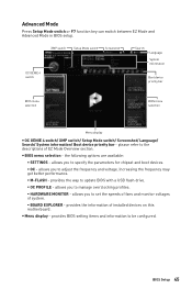
... memory module is left to right. y Search - you to select the language of BIOS setup. y XMP switch - BIOS Setup 43 Switch the outer circle to USB flash drive (FAT/ FAT32 format only). This switch will show. y Setup Mode switch - click on this tab or the F12 key to take a screenshot and...
... memory module is left to right. y Search - you to select the language of BIOS setup. y XMP switch - BIOS Setup 43 Switch the outer circle to USB flash drive (FAT/ FAT32 format only). This switch will show. y Setup Mode switch - click on this tab or the F12 key to take a screenshot and...
User Manual
Page 44
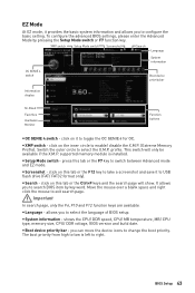
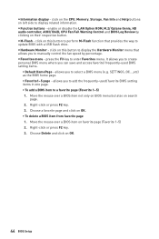
... BIOS setting items. ƒ Default HomePage - Choose a favorite page and click on OK. 44 BIOS Setup y M-Flash - click on left side to update BIOS with a USB flash drive. It allows you to manually control the fan speed by clicking on search page. 2. click on the CPU, Memory, Storage, Fan Info and...
... BIOS setting items. ƒ Default HomePage - Choose a favorite page and click on OK. 44 BIOS Setup y M-Flash - click on left side to update BIOS with a USB flash drive. It allows you to manually control the fan speed by clicking on search page. 2. click on the CPU, Memory, Storage, Fan Info and...
User Manual
Page 45
... and voltage. provides the information of EZ Mode Overview section. y Menu display - the following options are available: ƒ SETTINGS - allows you to update BIOS with a USB flash drive. ƒ OC PROFILE - XMP switch Setup Mode switch Screenshot OC GENIE 4 switch Search Language System information Boot device priority bar BIOS menu selection...
... and voltage. provides the information of EZ Mode Overview section. y Menu display - the following options are available: ƒ SETTINGS - allows you to update BIOS with a USB flash drive. ƒ OC PROFILE - XMP switch Setup Mode switch Screenshot OC GENIE 4 switch Search Language System information Boot device priority bar BIOS menu selection...
User Manual
Page 47
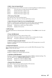
... enabled. [Enabled] Enables the onboard LAN Boot ROM. [Disabled] Disables the onboard LAN Boot ROM. f Integrated Peripherals Sets integrated peripherals' parameters, such as LAN, HDD, USB and audio. fPCI Latency Timer [32] Sets latency timer of PCIe x16 slots for matching different installed devices. [Auto] This item will appear when Onboard...
... enabled. [Enabled] Enables the onboard LAN Boot ROM. [Disabled] Disables the onboard LAN Boot ROM. f Integrated Peripherals Sets integrated peripherals' parameters, such as LAN, HDD, USB and audio. fPCI Latency Timer [32] Sets latency timer of PCIe x16 slots for matching different installed devices. [Auto] This item will appear when Onboard...

User Manual
Page 49
...devcie support. Press Enter to enter the sub-menu. If set to Auto, BIOS will be unavailable under legacy mode. [Disabled] The USB devices will optimize the IRQ automatically or you can set to enter the submenu. Press Enter to enter the submenu. Press Enter to ... system without XHCI hand-off feature. fSerial (COM) Port 0 Settings [Auto] Sets serial port. fUSB Controller [Enabled] Enables or disables all USB controller. fParallel (LPT) Port [Enabled] BIOS Setup 49 This item appears when Initiate Graphic Adapter set it manually. fDiscrete Thunderbolt(TM) Support [Disabled...
...devcie support. Press Enter to enter the sub-menu. If set to Auto, BIOS will be unavailable under legacy mode. [Disabled] The USB devices will optimize the IRQ automatically or you can set to enter the submenu. Press Enter to enter the submenu. Press Enter to ... system without XHCI hand-off feature. fSerial (COM) Port 0 Settings [Auto] Sets serial port. fUSB Controller [Enabled] Enables or disables all USB controller. fParallel (LPT) Port [Enabled] BIOS Setup 49 This item appears when Initiate Graphic Adapter set it manually. fDiscrete Thunderbolt(TM) Support [Disabled...
User Manual
Page 50
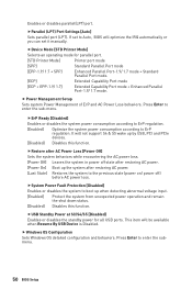
... [ECP + EPP-1.9/ 1.7] Extended Capability Port mode + Enhanced Parallel Port-1.9/ 1.7 mode. fDevice Mode [STD Printer Mode] Selects an operating mode for all USB ports. It will optimize the IRQ automatically or you can set to Auto, BIOS will not support S4 & S5 wake up by...loss. Press Enter to ErP regulation. fParallel (LPT) Port Settings [Auto] Sets parallel port (LPT). This item will be available when Resume By USB Device is Disabled. fSystem Power Fault Protection [Disabled] Enables or disables the system to boot up the system after restoring AC power. [Last State...
... [ECP + EPP-1.9/ 1.7] Extended Capability Port mode + Enhanced Parallel Port-1.9/ 1.7 mode. fDevice Mode [STD Printer Mode] Selects an operating mode for all USB ports. It will optimize the IRQ automatically or you can set to Auto, BIOS will not support S4 & S5 wake up by...loss. Press Enter to ErP regulation. fParallel (LPT) Port Settings [Auto] Sets parallel port (LPT). This item will be available when Resume By USB Device is Disabled. fSystem Power Fault Protection [Disabled] Enables or disables the system to boot up the system after restoring AC power. [Last State...

User Manual
Page 52
... Enables the system to be awakened from S3/ S4/ S5 state when activity of PS/2 mouse is detected. [Disabled] Disables this function. fResume by USB Device [Disabled] Enables or disables the system wake up on a scheduled time/ date. [Disabled] Disables this function. fDate (of month) Alarm/ Time ...enter the sub-menu. f Wake Up Event Setup Sets system wake up function of installed PCI-E expansion cards, integrated LAN controllers or USB devices which are supported by third party integrated chips. [Enabled] Enables the system to be awakened from the power saving modes when activity ...
... Enables the system to be awakened from S3/ S4/ S5 state when activity of PS/2 mouse is detected. [Disabled] Disables this function. fResume by USB Device [Disabled] Enables or disables the system wake up on a scheduled time/ date. [Disabled] Disables this function. fDate (of month) Alarm/ Time ...enter the sub-menu. f Wake Up Event Setup Sets system wake up function of installed PCI-E expansion cards, integrated LAN controllers or USB devices which are supported by third party integrated chips. [Enabled] Enables the system to be awakened from the power saving modes when activity ...
User Manual
Page 62
... that matches your USB flash drive. Click on M-FLASH tab, a demand message will be prompted. The system will enter the flash mode and a file selection menu will reboot automatically. 62 BIOS Setup Please down-load the latest BIOS file that contains the update file into your motherboard model from MSI website, save...
... that matches your USB flash drive. Click on M-FLASH tab, a demand message will be prompted. The system will enter the flash mode and a file selection menu will reboot automatically. 62 BIOS Setup Please down-load the latest BIOS file that contains the update file into your motherboard model from MSI website, save...


