
User Guide
Page 12
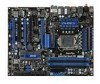
...Chipset ■ Intel® P55 chipset Memory Support ■ 4 DDR3 DIMMs support DDR3 2133 *(OC)/ 2000 *(OC)/ 1800 *(OC)/1600 *(OC)/ 1333/ 1066 DRAM (16GB Max) ■ Supports Dual-Channel mode *(For more information on compatible components, please visit http://www.msi.com/index.php?func=testreport...mode ■ Supports PIO, Bus Master operation mode SATA ■ 6 SATAII (SATA1~6) ports by Intel® P55 ■ 2 SATAII (SATA7, SATA8) ports by JMicron® JMB322 ■ 1 ESATA/ USB Combo port (back panel) by JMicron® JMB363 ■ Supports storage and data transfers at up to 3 ...
...Chipset ■ Intel® P55 chipset Memory Support ■ 4 DDR3 DIMMs support DDR3 2133 *(OC)/ 2000 *(OC)/ 1800 *(OC)/1600 *(OC)/ 1333/ 1066 DRAM (16GB Max) ■ Supports Dual-Channel mode *(For more information on compatible components, please visit http://www.msi.com/index.php?func=testreport...mode ■ Supports PIO, Bus Master operation mode SATA ■ 6 SATAII (SATA1~6) ports by Intel® P55 ■ 2 SATAII (SATA7, SATA8) ports by JMicron® JMB322 ■ 1 ESATA/ USB Combo port (back panel) by JMicron® JMB363 ■ Supports storage and data transfers at up to 3 ...
User Guide
Page 13
... 2 PCI slots, support 3.3V/ 5V PCI bus Interface Form Factor ■ ATX (30.5cm X 24.4 cm) Mounting ■ 9 mounting holes If you need...if you could search the product web page and find details on our web address below http://www.msi.com/index.php 1-3 MS-7581 Connectors ■ Back panel - 1 PS/2 keyboard port - 1...PDIF-out port - 1 Optical S/PDIF-out port - 1 IEEE 1394 port (optional) - 7 USB 2.0 ports - 1 ESATA/ USB Combo port - 2 LAN ports - 6 flexible audio ports ■ On-Board - 3 USB 2.0 connectors - 1 IEEE 1394 connector (optional) - 1 Chassis Intrusion connector - 1 CD-In connector...
... 2 PCI slots, support 3.3V/ 5V PCI bus Interface Form Factor ■ ATX (30.5cm X 24.4 cm) Mounting ■ 9 mounting holes If you need...if you could search the product web page and find details on our web address below http://www.msi.com/index.php 1-3 MS-7581 Connectors ■ Back panel - 1 PS/2 keyboard port - 1...PDIF-out port - 1 Optical S/PDIF-out port - 1 IEEE 1394 port (optional) - 7 USB 2.0 ports - 1 ESATA/ USB Combo port - 2 LAN ports - 6 flexible audio ports ■ On-Board - 3 USB 2.0 connectors - 1 IEEE 1394 connector (optional) - 1 Chassis Intrusion connector - 1 CD-In connector...

User Guide
Page 15
Packing Checklist MS-7581 MSI mainboard MSI Driver/Utility DVD SATA Cable Power Cable USB Bracket (Optional) Standard Cable for IDE Devices V-Check Cable CrossFireX Video Link Cable SLI Video Link Card Back IO Shield User's Guide * The pictures are for reference only and may vary from the packing contents of the product you purchased. 1-5
Packing Checklist MS-7581 MSI mainboard MSI Driver/Utility DVD SATA Cable Power Cable USB Bracket (Optional) Standard Cable for IDE Devices V-Check Cable CrossFireX Video Link Cable SLI Video Link Card Back IO Shield User's Guide * The pictures are for reference only and may vary from the packing contents of the product you purchased. 1-5

User Guide
Page 26
▍ Hardware Setup Back Panel Mouse Coaxial S/PDIF-Out (optional) 1394 Port LAN USB Port Keyboard Optical USB Port S/PDIF-Out ESATA/ USB USB Port Combo Port LAN Line-In RS-Out Line-Out CS-Out USB Port Mic SS-Out ▶ Mouse/Keyboard The standard PS/2® mouse/keyboard DIN... on the back panel provides connection to IEEE1394 devices. ▶ USB Port The USB (Universal Serial Bus) port is for attaching USB devices such as keyboard, mouse, or other USB-compatible devices. ▶ ESATA/USB Combo Port The ESATA/USB combo port is for attaching the ESATA external hard drive or...
▍ Hardware Setup Back Panel Mouse Coaxial S/PDIF-Out (optional) 1394 Port LAN USB Port Keyboard Optical USB Port S/PDIF-Out ESATA/ USB USB Port Combo Port LAN Line-In RS-Out Line-Out CS-Out USB Port Mic SS-Out ▶ Mouse/Keyboard The standard PS/2® mouse/keyboard DIN... on the back panel provides connection to IEEE1394 devices. ▶ USB Port The USB (Universal Serial Bus) port is for attaching USB devices such as keyboard, mouse, or other USB-compatible devices. ▶ ESATA/USB Combo Port The ESATA/USB combo port is for attaching the ESATA external hard drive or...

User Guide
Page 32
▍ Hardware Setup Front USB Connector: JUSB1 / JUSB2 / JUSB3 This connector, compliant with Intel® I/O Connectivity Design Guide, is ideal for connecting high-speed USB interface peripherals such as USB HDD, digital cameras, MP3 players, printers, modems and the like. 2.V4C.U6CS.U8BS1.DG0B-r.DUo+uSnBdOC 1.V3C.U5CS.U7BS.DG9B.-rNDoo+unPdin USB 2.0 Bracket (optional) Important Note that the pins of VCC and GND must be connected correctly to avoid possible damage. 2-16
▍ Hardware Setup Front USB Connector: JUSB1 / JUSB2 / JUSB3 This connector, compliant with Intel® I/O Connectivity Design Guide, is ideal for connecting high-speed USB interface peripherals such as USB HDD, digital cameras, MP3 players, printers, modems and the like. 2.V4C.U6CS.U8BS1.DG0B-r.DUo+uSnBdOC 1.V3C.U5CS.U7BS.DG9B.-rNDoo+unPdin USB 2.0 Bracket (optional) Important Note that the pins of VCC and GND must be connected correctly to avoid possible damage. 2-16
User Guide
Page 45
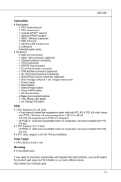
... the PCI bus pins as jumpers, switches or BIOS configuration. MS-7581 PCI (Peripheral Component Interconnect) Slot The PCI slot supports LAN card, SCSI card, USB card, and other add-on cards that comply with PCI specifications. 32-bit PCI Slot Important When adding or removing expansion cards, make sure that...
... the PCI bus pins as jumpers, switches or BIOS configuration. MS-7581 PCI (Peripheral Component Interconnect) Slot The PCI slot supports LAN card, SCSI card, USB card, and other add-on cards that comply with PCI specifications. 32-bit PCI Slot Important When adding or removing expansion cards, make sure that...

User Guide
Page 48
... user input at configuration display if needed / requested. Load Option ROM (VGA and RAID option ROM) form BIOS to OS Loader (typically INT 19H). Initialize USB device and different devices. ▍ Hardware Setup Standby LED Lights orange when the system is operating. Early CPU Initialize. Initialize onboard devices. Enter setup screen...
... user input at configuration display if needed / requested. Load Option ROM (VGA and RAID option ROM) form BIOS to OS Loader (typically INT 19H). Initialize USB device and different devices. ▍ Hardware Setup Standby LED Lights orange when the system is operating. Early CPU Initialize. Initialize onboard devices. Enter setup screen...
User Guide
Page 58
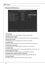
... This setting allows you to enable/disable the onboard USB controller. ▶ USB Device Legacy Support Select [Enabled] if you need to use a USB-interfaced device in the operating system. ▶ Onboard LAN Controller This setting allows you to enable/disable the onboard LAN controller. ▶ LAN Option ROM ...
... This setting allows you to enable/disable the onboard USB controller. ▶ USB Device Legacy Support Select [Enabled] if you need to use a USB-interfaced device in the operating system. ▶ Onboard LAN Controller This setting allows you to enable/disable the onboard LAN controller. ▶ LAN Option ROM ...

User Guide
Page 61
... the following fields to set to [Enabled], the feature allows your system to be awakened from what power saving modes when input signal of the USB device to indicate the sleep/suspend state. ▶ Restore On AC Power Loss This item specifies whether your system will reboot after a power failure or...] The power LED blinks to wake up events. Setting to [OS], the wake up events will be defined by OS. ▶ Resume From S3 By USB Device The item allows the activity of the PS/2 keyboard/ mouse is set to indicate the sleep/suspend state. MS-7581 ▶ Power LED When...
... the following fields to set to [Enabled], the feature allows your system to be awakened from what power saving modes when input signal of the USB device to indicate the sleep/suspend state. ▶ Restore On AC Power Loss This item specifies whether your system will reboot after a power failure or...] The power LED blinks to wake up events. Setting to [OS], the wake up events will be defined by OS. ▶ Resume From S3 By USB Device The item allows the activity of the PS/2 keyboard/ mouse is set to indicate the sleep/suspend state. MS-7581 ▶ Power LED When...

User Guide
Page 66
▍ BIOS Setup BIOS Setting Password When you select this function, a message as below will appear on the screen: ▶ U-Key This item is used to enable/ disable USB driver device as a key. ▶ Make U-Key at This item is used to specify the USB driver device as a key. ▶ Change Supervisor Password This item is used to set the supervisor password. ▶ Change User Password This item is used to set the user password. 3-18
▍ BIOS Setup BIOS Setting Password When you select this function, a message as below will appear on the screen: ▶ U-Key This item is used to enable/ disable USB driver device as a key. ▶ Make U-Key at This item is used to specify the USB driver device as a key. ▶ Change Supervisor Password This item is used to set the supervisor password. ▶ Change User Password This item is used to set the user password. 3-18

User Guide
Page 76
...format only), or allows the system to boot from the BIOS file inside USB drive. Update BIOS ROM chip data from selected file, which saved in the root directory of USB drive. Note: this particular BIOS inside USB drive (FAT/ FAT32 format only). [Disabled] Disable M-Flash function. [...BIOS Update] Flash BIOS via the USB/ Storage drive directly. System will boot from this BIOS file which ...
...format only), or allows the system to boot from the BIOS file inside USB drive. Update BIOS ROM chip data from selected file, which saved in the root directory of USB drive. Note: this particular BIOS inside USB drive (FAT/ FAT32 format only). [Disabled] Disable M-Flash function. [...BIOS Update] Flash BIOS via the USB/ Storage drive directly. System will boot from this BIOS file which ...

User Guide
Page 78
.... ▶ Start to save file Press "Enter" and select "OK" the system will stare to save BIOS file from the USB/ Storage (FAT/32 format only) drive. == Backup BIOS to USB drive == The following fields are used to read the onboard BIOS ROM data, and save it only supports FAT/ FAT32 file... system drive. ▶ Save File Name as Please setup a specific name for the BIOS file, which will be saved into the USB drive/ storage drive. ▍ BIOS Setup ▶ Load BIOS source file from When the M-Flash function as sets to [Boot] or [BIOS Update], this item...
.... ▶ Start to save file Press "Enter" and select "OK" the system will stare to save BIOS file from the USB/ Storage (FAT/32 format only) drive. == Backup BIOS to USB drive == The following fields are used to read the onboard BIOS ROM data, and save it only supports FAT/ FAT32 file... system drive. ▶ Save File Name as Please setup a specific name for the BIOS file, which will be saved into the USB drive/ storage drive. ▍ BIOS Setup ▶ Load BIOS source file from When the M-Flash function as sets to [Boot] or [BIOS Update], this item...
User Guide
Page 122
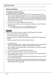
...driver. 5. For Windows Vista: During the Operating system installation, after the RAID volume is done. 4. For Windows Vista you can use the USB floppy drive only. Important Please follow the instruction below to make an "Intel® RAID Driver" for Intel® PCH RAID Controller is ... and press Enter. 6. When prompted, insert the floppy disk or media (CD/DVD or USB) you are ready to a formatted floppy diskette. • The driver diskette for yourself. • Insert the MSI DVD into the A: drive. Leave the disk in the right place and are already in the...
...driver. 5. For Windows Vista: During the Operating system installation, after the RAID volume is done. 4. For Windows Vista you can use the USB floppy drive only. Important Please follow the instruction below to make an "Intel® RAID Driver" for Intel® PCH RAID Controller is ... and press Enter. 6. When prompted, insert the floppy disk or media (CD/DVD or USB) you are ready to a formatted floppy diskette. • The driver diskette for yourself. • Insert the MSI DVD into the A: drive. Leave the disk in the right place and are already in the...


