
User Guide
Page 10
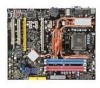
Designed to fit the advanced Intel® Core 2 Quad/Core 2 Duo/Pentium/Celeron LGA775 processor, the P35D3 Platinum Series deliver a high performance and professional desktop platform solution. 1-1 Getting Started Chapter 1 Getting Started Thank you for optimal system efficiency. The P35D3 Platinum Series mainboards are based on Intel® P35 & ICH9R chipsets for choosing the P35D3 Platinum Series (MS7356 v1.X) ATX mainboard.
Designed to fit the advanced Intel® Core 2 Quad/Core 2 Duo/Pentium/Celeron LGA775 processor, the P35D3 Platinum Series deliver a high performance and professional desktop platform solution. 1-1 Getting Started Chapter 1 Getting Started Thank you for optimal system efficiency. The P35D3 Platinum Series mainboards are based on Intel® P35 & ICH9R chipsets for choosing the P35D3 Platinum Series (MS7356 v1.X) ATX mainboard.

User Guide
Page 12
Support 3.3V/ 5V PCI bus Interface Form Factor - ATX (30.5cm X 24.5cm) Mounting - 9 mounting holes 1-3 Getting Started Connectors Back panel - 1 PS/2 mouse port - 1 PS/2 keyboard port - 2 eSATA ports (support Command Based Port Multipliers) - 6 ...
Support 3.3V/ 5V PCI bus Interface Form Factor - ATX (30.5cm X 24.5cm) Mounting - 9 mounting holes 1-3 Getting Started Connectors Back panel - 1 PS/2 mouse port - 1 PS/2 keyboard port - 2 eSATA ports (support Command Based Port Multipliers) - 6 ...

User Guide
Page 13
... SYSFAN4 DIMM3 DIMM4 DIMM1 DIMM2 SATA4 SATA3 IC IHn9tRel SATA6 SATA5 JCASE1 B AT T + SATA7 SW1 IDE1 FDD1 SYSFAN3 J1394_ 1 JUSB3 JFP2 JFP1 JUSB2 JUSB1 ATX1 P35D3 Platinum Series (MS-7356 v1.X) ATX Mainboard 1-4
... SYSFAN4 DIMM3 DIMM4 DIMM1 DIMM2 SATA4 SATA3 IC IHn9tRel SATA6 SATA5 JCASE1 B AT T + SATA7 SW1 IDE1 FDD1 SYSFAN3 J1394_ 1 JUSB3 JFP2 JFP1 JUSB2 JUSB1 ATX1 P35D3 Platinum Series (MS-7356 v1.X) ATX Mainboard 1-4
User Guide
Page 14
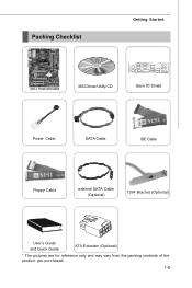
Packing Checklist Getting Started MSI motherboard MSI Driver/Utility CD Back IO Shield Power Cable SATA Cable IDE Cable Floppy Cable external SATA Cable (Optional) 1394 Bracket (Optional) User's Guide and Quick Guide ATX Extender (Optional) * The pictures are for reference only and may vary from the packing contents of the product you purchased. 1-5
Packing Checklist Getting Started MSI motherboard MSI Driver/Utility CD Back IO Shield Power Cable SATA Cable IDE Cable Floppy Cable external SATA Cable (Optional) 1394 Bracket (Optional) User's Guide and Quick Guide ATX Extender (Optional) * The pictures are for reference only and may vary from the packing contents of the product you purchased. 1-5

User Guide
Page 17
.... Introduction to LGA 775 CPU The pin-pad side of LGA 775 CPU. For the latest information about CPU, please visit http://global.msi.com.tw/index.php? Make sure that you are able to tolerate such abnormal setting, while doing overclocking. Remember to apply some thermal ... Always make sure your dealer before turning on it for better heat dispersion. Replaceing the CPU While replacing the CPU, always turn off the ATX power supply or unplug the power supply's power cord from overheating. Overclocking This mainboard is the Pin 1 indicator 2-3 Alignment Key Alignment Key Yellow...
.... Introduction to LGA 775 CPU The pin-pad side of LGA 775 CPU. For the latest information about CPU, please visit http://global.msi.com.tw/index.php? Make sure that you are able to tolerate such abnormal setting, while doing overclocking. Remember to apply some thermal ... Always make sure your dealer before turning on it for better heat dispersion. Replaceing the CPU While replacing the CPU, always turn off the ATX power supply or unplug the power supply's power cord from overheating. Overclocking This mainboard is the Pin 1 indicator 2-3 Alignment Key Alignment Key Yellow...
User Guide
Page 25
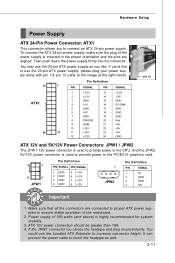
...GND 8 PW R OK 20 Res 9 5VSB 21 +5V 10 +12V 22 +5V 12 11 +12V 23 +5V 12 +3.3V 24 GND pin 13 pin 12 ATX 12V and 5V/12V Power Connectors: JPW1 / JPW2 The JPW 1 12V power connector is inserted in the proper orientation and the pins are connected to... proper ATX power supplies to the PCIEX16 graphics card. 5 1 8 4 JPW1 Pin Definition PIN SIGNAL PIN SIGNAL 1 GND 2 GND 3 GND 4 GND 5 +12V 6 +12V 7 +12V 8 +12V 1 JPW2 Pin ...
...GND 8 PW R OK 20 Res 9 5VSB 21 +5V 10 +12V 22 +5V 12 11 +12V 23 +5V 12 +3.3V 24 GND pin 13 pin 12 ATX 12V and 5V/12V Power Connectors: JPW1 / JPW2 The JPW 1 12V power connector is inserted in the proper orientation and the pins are connected to... proper ATX power supplies to the PCIEX16 graphics card. 5 1 8 4 JPW1 Pin Definition PIN SIGNAL PIN SIGNAL 1 GND 2 GND 3 GND 4 GND 5 +12V 6 +12V 7 +12V 8 +12V 1 JPW2 Pin ...


