User Guide
Page 4
... not occur in accordance with the instructions, may cause undesired operation. This equipment generates, uses and can be used in a particular installation. Micro-Star International MS-7345 This device complies with Part 15 of the FCC Rules. FCC-B Radio Frequency Interference Statement T h is eq uip men t h as been tested and found to...
... not occur in accordance with the instructions, may cause undesired operation. This equipment generates, uses and can be used in a particular installation. Micro-Star International MS-7345 This device complies with Part 15 of the FCC Rules. FCC-B Radio Frequency Interference Statement T h is eq uip men t h as been tested and found to...
User Guide
Page 10
Designed to fit the advanced Intel® Core 2 Quad/Core 2 Duo/Pentium/Celeron LGA775 processor, the P35 Neo2 Series deliver a high performance and professional desktop platform solution. 1-1 Getting Started Chapter 1 Getting Started Thank you for optimal system efficiency. The P35 Neo2 Series mainboards are based on Intel® P35 & ICH9/ICH9R chipsets for choosing the P35 Neo2 Series (MS-7345 v1.X) ATX mainboard.
Designed to fit the advanced Intel® Core 2 Quad/Core 2 Duo/Pentium/Celeron LGA775 processor, the P35 Neo2 Series deliver a high performance and professional desktop platform solution. 1-1 Getting Started Chapter 1 Getting Started Thank you for optimal system efficiency. The P35 Neo2 Series mainboards are based on Intel® P35 & ICH9/ICH9R chipsets for choosing the P35 Neo2 Series (MS-7345 v1.X) ATX mainboard.
User Guide
Page 11
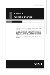
...func =t est report ) LAN - Flexible 8-channel audio with 360KB, 720KB, 1.2MB, 1.44MB and 2.88MB 1-2 c om . North Bridge: Intel® P35 chipset - m si. About ports of SATAII please check Intel website and based on PCB version. - South Bridge: Intel® ICH9/ICH9R Base chipset Memory... by VIA VT6308 (optional) FDD - 1 floppy port - Supports storage and data transfers at up to 300 MB/s 1394 - MS-7345 Mainboard Mainboard Specifications Processor Support - Compliant with Azalia 1.0 Spec - Support Intel® Yorkfield, Wolfdale (For the latest information about CPU, ...
...func =t est report ) LAN - Flexible 8-channel audio with 360KB, 720KB, 1.2MB, 1.44MB and 2.88MB 1-2 c om . North Bridge: Intel® P35 chipset - m si. About ports of SATAII please check Intel website and based on PCB version. - South Bridge: Intel® ICH9/ICH9R Base chipset Memory... by VIA VT6308 (optional) FDD - 1 floppy port - Supports storage and data transfers at up to 300 MB/s 1394 - MS-7345 Mainboard Mainboard Specifications Processor Support - Compliant with Azalia 1.0 Spec - Support Intel® Yorkfield, Wolfdale (For the latest information about CPU, ...
User Guide
Page 13
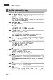
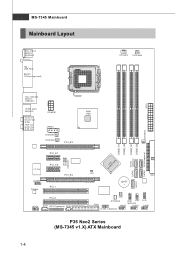
MS-7345 Mainboard Mainboard Layout Top : mou se Botto m: keybo ar d Top : USB Ports Bottom: CPUFA N SYSFAN5 Top : LAN j ack Botto m: USB po rts eSATA ports (option ... D1 JC D3 JSL IC1(optional) SPDO Intel P35 SYSFAN3 DI MM _B1 DI MM _B2 DI MM _A1 DI MM _A2 SATA5 SATA3(optional) SATA4 (optional) I CH 9/ II nCtHel9 R SATA6 JCI1 B AT T + IDE1 S ATA7 SW1 FDD1 SYSFAN2 JDB1 JFP2 (optional) JUSB3 JUSB2 J1394_1(optional) JFP1 JUSB1 ATX1 P35 Neo2 Series (MS-7345 v1.X) ATX Mainboard 1-4
MS-7345 Mainboard Mainboard Layout Top : mou se Botto m: keybo ar d Top : USB Ports Bottom: CPUFA N SYSFAN5 Top : LAN j ack Botto m: USB po rts eSATA ports (option ... D1 JC D3 JSL IC1(optional) SPDO Intel P35 SYSFAN3 DI MM _B1 DI MM _B2 DI MM _A1 DI MM _A2 SATA5 SATA3(optional) SATA4 (optional) I CH 9/ II nCtHel9 R SATA6 JCI1 B AT T + IDE1 S ATA7 SW1 FDD1 SYSFAN2 JDB1 JFP2 (optional) JUSB3 JUSB2 J1394_1(optional) JFP1 JUSB1 ATX1 P35 Neo2 Series (MS-7345 v1.X) ATX Mainboard 1-4
User Guide
Page 18
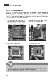
... the damage of your system. 2. The pins of the CPU land side cover depends on the top to prevent overheating. The availability of socket reveal. 4. MS-7345 Mainboard CPU & Cooler Installation W hen you install the CPU, always cover it to protect the contact from lever hinge side (as the arrow shows). 3. Confirm...
... the damage of your system. 2. The pins of the CPU land side cover depends on the top to prevent overheating. The availability of socket reveal. 4. MS-7345 Mainboard CPU & Cooler Installation W hen you install the CPU, always cover it to protect the contact from lever hinge side (as the arrow shows). 3. Confirm...
User Guide
Page 20
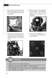
... demonstration of your CPU socket pin with the plastic cap covered (shown in BIOS (Chapter 3). 2. Read the CPU status in Figure 1) to fasten the cooler. MS-7345 Mainboard 9. The appearance of the CPU/ cooler installation only. locking switch Important 1. Then rotate the locking switch (refer to the correct direction marked on the...
... demonstration of your CPU socket pin with the plastic cap covered (shown in BIOS (Chapter 3). 2. Read the CPU status in Figure 1) to fasten the cooler. MS-7345 Mainboard 9. The appearance of the CPU/ cooler installation only. locking switch Important 1. Then rotate the locking switch (refer to the correct direction marked on the...
User Guide
Page 22
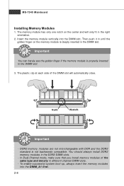
Important You can barely see the golden finger if the memory module is properly inserted in the DDR2 DIMM slots. - MS-7345 Mainboard Installing Memory Modules 1. Volt Notch Important - Then push it in until the golden finger on the center and will automatically close. The plastic clip ...
Important You can barely see the golden finger if the memory module is properly inserted in the DDR2 DIMM slots. - MS-7345 Mainboard Installing Memory Modules 1. Volt Notch Important - Then push it in until the golden finger on the center and will automatically close. The plastic clip ...
User Guide
Page 24
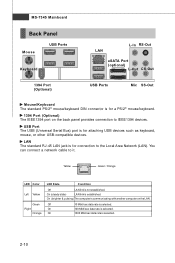
... link is selected. 2-10 On 100 Mbit/sec data rate is for a PS/2® mouse/keyboard. 1394 Port (Optional) The IEEE1394 port on the LAN. MS-7345 Mainboard Back Panel Mouse USB Ports Keyboard LAN L-In RS-Out eSATA Port (optional) L-Out CS-Out 1394 Port (Optional) USB Ports Mic SS-Out...
... link is selected. 2-10 On 100 Mbit/sec data rate is for a PS/2® mouse/keyboard. 1394 Port (Optional) The IEEE1394 port on the LAN. MS-7345 Mainboard Back Panel Mouse USB Ports Keyboard LAN L-In RS-Out eSATA Port (optional) L-Out CS-Out 1394 Port (Optional) USB Ports Mic SS-Out...
User Guide
Page 26
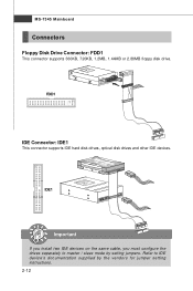
Refer to master / slave mode by the vendors for jumper setting instructions. 2-12 IDE1 Important If you install two IDE devices on the same cable, you must configure the drives separately to IDE device's documentation supplied by setting jumpers. MS-7345 Mainboard Connectors Floppy Disk Drive Connector: FDD1 This connector supports 360KB, 720KB, 1.2MB, 1.44MB or 2.88MB floppy disk drive. FDD1 IDE Connector: IDE1 This connector supports IDE hard disk drives, optical disk drives and other IDE devices.
Refer to master / slave mode by the vendors for jumper setting instructions. 2-12 IDE1 Important If you install two IDE devices on the same cable, you must configure the drives separately to IDE device's documentation supplied by setting jumpers. MS-7345 Mainboard Connectors Floppy Disk Drive Connector: FDD1 This connector supports 360KB, 720KB, 1.2MB, 1.44MB or 2.88MB floppy disk drive. FDD1 IDE Connector: IDE1 This connector supports IDE hard disk drives, optical disk drives and other IDE devices.
User Guide
Page 28
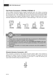
... intrusion switch cable. CINTRU GND 2-14 2 1 JCI1 The system will be connected to the +12V; If the chassis is the positive and should be activated. MS-7345 Mainboard Fan Power Connectors: CPUFAN, SYSFAN1~5 The fan power connectors support system cooling fan with 3 or 4 pins power connector are both available for proper CPU...
... intrusion switch cable. CINTRU GND 2-14 2 1 JCI1 The system will be connected to the +12V; If the chassis is the positive and should be activated. MS-7345 Mainboard Fan Power Connectors: CPUFAN, SYSFAN1~5 The fan power connectors support system cooling fan with 3 or 4 pins power connector are both available for proper CPU...
User Guide
Page 30
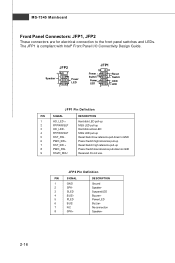
... LEDs. The JFP1 is compliant with Intel® Front Panel I/O Connectivity Design Guide. JFP2 +8 7 Speaker + 21 Power LED JFP1 10 Power Switch + Power LED 2 9 + Reset - MS-7345 Mainboard Front Panel Connectors: JFP1, JFP2 These connectors are for electrical connection to GND Reserved.
... LEDs. The JFP1 is compliant with Intel® Front Panel I/O Connectivity Design Guide. JFP2 +8 7 Speaker + 21 Power LED JFP1 10 Power Switch + Power LED 2 9 + Reset - MS-7345 Mainboard Front Panel Connectors: JFP1, JFP2 These connectors are for electrical connection to GND Reserved.
User Guide
Page 32
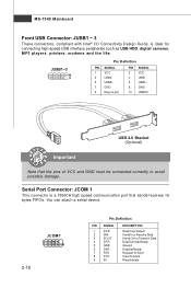
... 3 USB0- 5 USB0+ 7 GND 9 Key (no pin) PIN SIGNAL 2 VCC 4 USB1- 6 USB1+ 8 GND 10 USBOC USB 2.0 Bracket (Optional) Important Note that sends/receives 16 bytes FIFOs. MS-7345 Mainboard Front USB Connector: JUSB1 ~ 3 These connectors, compliant with Intel® I/O Connectivity Design Guide, is a 16550A high speed communication port that the pins of VCC...
... 3 USB0- 5 USB0+ 7 GND 9 Key (no pin) PIN SIGNAL 2 VCC 4 USB1- 6 USB1+ 8 GND 10 USBOC USB 2.0 Bracket (Optional) Important Note that sends/receives 16 bytes FIFOs. MS-7345 Mainboard Front USB Connector: JUSB1 ~ 3 These connectors, compliant with Intel® I/O Connectivity Design Guide, is a 16550A high speed communication port that the pins of VCC...
User Guide
Page 34
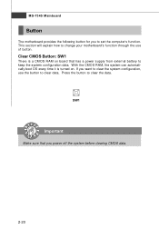
... a CMOS RAM on . Clear CMOS Button: SW1 There is turned on board that you power off the system before clearing CMOS data. 2-20 MS-7345 Mainboard Button The motherboard provides the following button for you want to clear the system configuration, use of button. If you to keep the system configuration data. SW1... has a power supply from external battery to set the computer's function. Press the button to clear data. This section will explain how to change your motherboard's function through the use the button to clear the data.
... a CMOS RAM on . Clear CMOS Button: SW1 There is turned on board that you power off the system before clearing CMOS data. 2-20 MS-7345 Mainboard Button The motherboard provides the following button for you want to clear the system configuration, use of button. If you to keep the system configuration data. SW1... has a power supply from external battery to set the computer's function. Press the button to clear data. This section will explain how to change your motherboard's function through the use the button to clear the data.
User Guide
Page 36
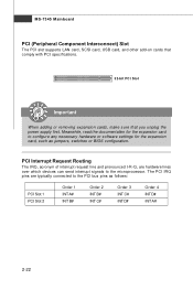
.... The PCI IRQ pins are hardware lines over which devices can send interrupt signals to the PCI bus pins as jumpers, switches or BIOS configuration. MS-7345 Mainboard PCI (Peripheral Component Interconnect) Slot The PCI slot supports LAN card, SCSI card, USB card, and other add-on cards that comply with PCI...
.... The PCI IRQ pins are hardware lines over which devices can send interrupt signals to the PCI bus pins as jumpers, switches or BIOS configuration. MS-7345 Mainboard PCI (Peripheral Component Interconnect) Slot The PCI slot supports LAN card, SCSI card, USB card, and other add-on cards that comply with PCI...

User Guide
Page 38
... to identify system problems through 16 various combinations of LED signals. Group4 Group3 Group2 Group1 Testing VGA BIOS This will initialize IDE drive and controller. MS-7345 Mainboard LED 7, 8, 9 ,10, 17, 18, 19, 20 These four LEDs allow users to RAM for fast booting. Group4 Group3 Group2 Group1 BIOS Sign On This...
... to identify system problems through 16 various combinations of LED signals. Group4 Group3 Group2 Group1 Testing VGA BIOS This will initialize IDE drive and controller. MS-7345 Mainboard LED 7, 8, 9 ,10, 17, 18, 19, 20 These four LEDs allow users to RAM for fast booting. Group4 Group3 Group2 Group1 BIOS Sign On This...
User Guide
Page 40
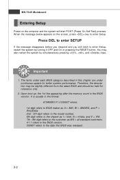
.... 2nd - 5th digit refers to the model number. 6th digit refers to the chipset as MS = all standard customers. You may be slightly different from the latest BIOS and should be held for better system performance. MS-7345 Mainboard Entering Setup Power on the screen, press key to enter Setup, restart the system...
.... 2nd - 5th digit refers to the model number. 6th digit refers to the chipset as MS = all standard customers. You may be slightly different from the latest BIOS and should be held for better system performance. MS-7345 Mainboard Entering Setup Power on the screen, press key to enter Setup, restart the system...
User Guide
Page 42
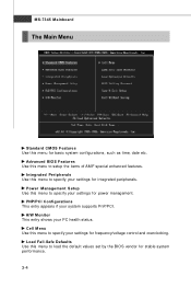
... for basic system configurations, such as time, date etc. Advanced BIOS Features Use this menu to setup the items of AMI® special enhanced features. MS-7345 Mainboard The Main Menu Standard CMOS Features Use this menu for stable system performance. 3-4
... for basic system configurations, such as time, date etc. Advanced BIOS Features Use this menu to setup the items of AMI® special enhanced features. MS-7345 Mainboard The Main Menu Standard CMOS Features Use this menu for stable system performance. 3-4
User Guide
Page 44
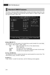
... the following screen appears. 3-6 year The year can be adjusted by numeric function keys. The time format is . day Day of the week, from Jan. MS-7345 Mainboard Standard CMOS Features The items in each item. Date (MM:DD:YY) This allows you to select the value you want in Standard CMOS...
... the following screen appears. 3-6 year The year can be adjusted by numeric function keys. The time format is . day Day of the week, from Jan. MS-7345 Mainboard Standard CMOS Features The items in each item. Date (MM:DD:YY) This allows you to select the value you want in Standard CMOS...
User Guide
Page 46
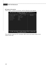
MS-7345 Mainboard System Information Press to enter the sub-menu, and the following screen appears. This sub-menu shows the CPU information, BIOS version and memory status of your system (read only). 3-8
MS-7345 Mainboard System Information Press to enter the sub-menu, and the following screen appears. This sub-menu shows the CPU information, BIOS version and memory status of your system (read only). 3-8
User Guide
Page 48
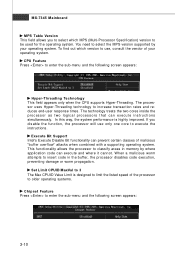
... memory by your operating system. W hen a malicious worm attempts to classify areas in the buffer, the processor disables code execution, preventing damage or worm propagation. MS-7345 Mainboard MPS Table Version This field allows you disable the f unction, the processor will use , consult the vendor of malicious "buffer overflow" attacks when combined...
... memory by your operating system. W hen a malicious worm attempts to classify areas in the buffer, the processor disables code execution, preventing damage or worm propagation. MS-7345 Mainboard MPS Table Version This field allows you disable the f unction, the processor will use , consult the vendor of malicious "buffer overflow" attacks when combined...


