User Guide
Page 3
...INTERNATIONAL. Alternatively, please try the following help resources for FAQ, technical guide, BIOS updates, driver updates, and other information: http://www.msi.com.tw/ Contact our technical staff at: support@msi.com.tw iii Copyright Notice The material in the preparation of this document is... are registered trademarks of International Business Machines Corporation. Revision History Revision V2.0 Revision History First release for PCB v2.X with Intel 845GE & ICH4 Date September 2002 Technical Support If a problem arises with your system and no guarantee is given as to make changes...
...INTERNATIONAL. Alternatively, please try the following help resources for FAQ, technical guide, BIOS updates, driver updates, and other information: http://www.msi.com.tw/ Contact our technical staff at: support@msi.com.tw iii Copyright Notice The material in the preparation of this document is... are registered trademarks of International Business Machines Corporation. Revision History Revision V2.0 Revision History First release for PCB v2.X with Intel 845GE & ICH4 Date September 2002 Technical Support If a problem arises with your system and no guarantee is given as to make changes...
User Guide
Page 5
... iii Revision History iii Technical Support iii Safety Instructions iv Chapter 1. Getting Started 1-1 Mainboard Specifications 1-2 Mainboard Layout 1-4 MSI Special Features 1-5 PC Alert 4 1-5 Fuzzy Logic 4 1-6 Live Monitor 1-7 D-Bracket 2 (optional 1-8 Live BIOS/Live Driver 1-10 S-Bracket (optional 1-11 MSI DVD 5.1 Channel (optional 1-12 Chapter 2. Hardware Setup 2-1 Quick Components Guide 2-2 Central Processing Unit: CPU 2-3 CPU Core...
... iii Revision History iii Technical Support iii Safety Instructions iv Chapter 1. Getting Started 1-1 Mainboard Specifications 1-2 Mainboard Layout 1-4 MSI Special Features 1-5 PC Alert 4 1-5 Fuzzy Logic 4 1-6 Live Monitor 1-7 D-Bracket 2 (optional 1-8 Live BIOS/Live Driver 1-10 S-Bracket (optional 1-11 MSI DVD 5.1 Channel (optional 1-12 Chapter 2. Hardware Setup 2-1 Quick Components Guide 2-2 Central Processing Unit: CPU 2-3 CPU Core...
User Guide
Page 6
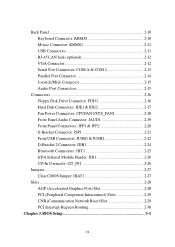
... 2-28 AGP (Accelerated Graphics Port) Slot 2-28 PCI (Peripheral Component Interconnect) Slots 2-29 CNR (Communication Network Riser) Slot 2-29 PCI Interrupt Request Routing 2-30 Chapter 3. BIOS Setup 3-1 vi
... 2-28 AGP (Accelerated Graphics Port) Slot 2-28 PCI (Peripheral Component Interconnect) Slots 2-29 CNR (Communication Network Riser) Slot 2-29 PCI Interrupt Request Routing 2-30 Chapter 3. BIOS Setup 3-1 vi
User Guide
Page 7
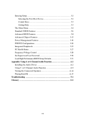
... A-14 Playing KaraOK A-15 Troubleshooting T-1 Glossary ...G-1 vii Entering Setup 3-2 Selecting the First Boot Device 3-2 Control Keys 3-3 Getting Help 3-3 The Main Menu 3-4 Standard CMOS Features 3-6 Advanced BIOS Features 3-8 Advanced Chipset Features 3-13 Power Management Features 3-16 PNP/PCI Configurations 3-20 Integrated Peripherals 3-23 PC Health Status 3-27 Frequency/Voltage Control 3-28 Set...
... A-14 Playing KaraOK A-15 Troubleshooting T-1 Glossary ...G-1 vii Entering Setup 3-2 Selecting the First Boot Device 3-2 Control Keys 3-3 Getting Help 3-3 The Main Menu 3-4 Standard CMOS Features 3-6 Advanced BIOS Features 3-8 Advanced Chipset Features 3-13 Power Management Features 3-16 PNP/PCI Configurations 3-20 Integrated Peripherals 3-23 PC Health Status 3-27 Frequency/Voltage Control 3-28 Set...
User Guide
Page 10
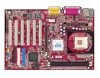
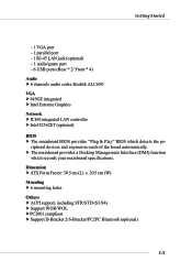
... jack (optional) - 1 audio/game port - 6 USB ports (Rear * 2/ Front * 4) Audio h 6 channels audio codec Realtek ALC650 VGA h 845GE integrated h Intel Extreme Graphics Network h ICH4 integrated LAN controller h Intel 82562ET (optional) BIOS h The mainboard BIOS provides "Plug & Play" BIOS which records your mainboard specifications. Dimension h ATX Form Factor: 30.5 cm (L) x 20.5 cm (W) Mounting h 6 mounting holes Others...
... jack (optional) - 1 audio/game port - 6 USB ports (Rear * 2/ Front * 4) Audio h 6 channels audio codec Realtek ALC650 VGA h 845GE integrated h Intel Extreme Graphics Network h ICH4 integrated LAN controller h Intel 82562ET (optional) BIOS h The mainboard BIOS provides "Plug & Play" BIOS which records your mainboard specifications. Dimension h ATX Form Factor: 30.5 cm (L) x 20.5 cm (W) Mounting h 6 mounting holes Others...
User Guide
Page 11
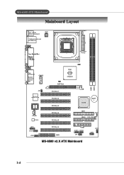
A W CD_IN1 Codec PCI Slot 1 PCI Slot 2 PCI Slot 3 PCI Slot 4 PCI Slot 5 ICH 4 BATT + IDE 1 JBAT1 IDE 2 SYS_FAN1 JSP1 JAUD1 JDB1 PCI Slot 6 CNR FDD1 JUSB1 JUSB2 JBT1 MS-6580 v2.X ATX Mainboard JFP2 JFP1 1-4 MS-6580 ATX Mainboard Mainboard Layout Top : mouse Bottom: keyboard JPW1 T:LAN jack (optional) B:USB ports CPUFAN1 ATX Power Supply Top : Game port Bottom: Line-Out Line-In Mic Intel 845GE chipset AGP Slot BIOS DDR 1 DDR 2 JIR1 W i n b o nd W 8 36 2 7 H F-
A W CD_IN1 Codec PCI Slot 1 PCI Slot 2 PCI Slot 3 PCI Slot 4 PCI Slot 5 ICH 4 BATT + IDE 1 JBAT1 IDE 2 SYS_FAN1 JSP1 JAUD1 JDB1 PCI Slot 6 CNR FDD1 JUSB1 JUSB2 JBT1 MS-6580 v2.X ATX Mainboard JFP2 JFP1 1-4 MS-6580 ATX Mainboard Mainboard Layout Top : mouse Bottom: keyboard JPW1 T:LAN jack (optional) B:USB ports CPUFAN1 ATX Power Supply Top : Game port Bottom: Line-Out Line-In Mic Intel 845GE chipset AGP Slot BIOS DDR 1 DDR 2 JIR1 W i n b o nd W 8 36 2 7 H F-
User Guide
Page 13
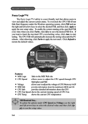
... MSI Info provides information about the mainboard, BIOS and OS Ø CPU Info provides detailed information about the CPU Ø CPU Fan Speed shows the current running at the specified FSB every time when you want to know the maximal CPU overclocking value, click Auto to start testing. MS-6580... ATX Mainboard Fuzzy Logic™ 4 The Fuzzy Logic™ 4 utility is a user friendly tool that allows users to restore the default values. ply to adjust the voltage of CPU Fan Ø CPU Temp. Features: Ø MSI Logo links to the MSI Web site Ø...
... MSI Info provides information about the mainboard, BIOS and OS Ø CPU Info provides detailed information about the CPU Ø CPU Fan Speed shows the current running at the specified FSB every time when you want to know the maximal CPU overclocking value, click Auto to start testing. MS-6580... ATX Mainboard Fuzzy Logic™ 4 The Fuzzy Logic™ 4 utility is a user friendly tool that allows users to restore the default values. ply to adjust the voltage of CPU Fan Ø CPU Temp. Features: Ø MSI Logo links to the MSI Web site Ø...
User Guide
Page 14
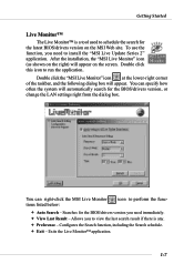
...216; Exit - Double click this icon to view the last search result if there is a tool used to schedule the search for the BIOS/drivers version, or change the LAN settings right from the dialog box. You can specify how often the system will automatically search for the ...latest BIOS/drivers version on the right) will appear. After the installation, the "MSI Live Monitor" icon (as shown on the MSI Web site. Searches for the BIOS/drivers version you need immediately. Ø View Last Result - To use...
...216; Exit - Double click this icon to view the last search result if there is a tool used to schedule the search for the BIOS/drivers version, or change the LAN settings right from the dialog box. You can specify how often the system will automatically search for the ...latest BIOS/drivers version on the right) will appear. After the installation, the "MSI Live Monitor" icon (as shown on the MSI Web site. Searches for the BIOS/drivers version you need immediately. Ø View Last Result - To use...
User Guide
Page 15
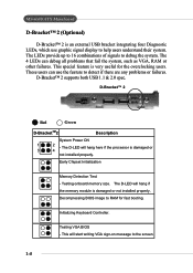
... to 16 combinations of signals to RAM for the overclocking users. D-Bracket™ 2 1 2 3 4 Red Green D-BracketTM2 Description System Power ON 1 2 - Testing VGA BIOS - D-Bracket™ 2 supports both USB 1.1 & 2.0 spec. MS-6580 ATX Mainboard D-Bracket™ 2 (Optional) D-Bracket™ 2 is damaged or 3 4 not installed properly. The D-LED will hang here if the processor is...
... to 16 combinations of signals to RAM for the overclocking users. D-Bracket™ 2 1 2 3 4 Red Green D-BracketTM2 Description System Power ON 1 2 - Testing VGA BIOS - D-Bracket™ 2 supports both USB 1.1 & 2.0 spec. MS-6580 ATX Mainboard D-Bracket™ 2 (Optional) D-Bracket™ 2 is damaged or 3 4 not installed properly. The D-LED will hang here if the processor is...
User Guide
Page 16
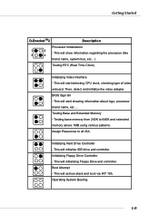
... processor (like brand name, system bus, etc...) Testing RTC (Real Time Clock) Initializing Video Interface - This will set low stack and boot via INT 19h. BIOS Sign On - Getting Started D-BracketTM2 Description Processor Initialization 1 3 2 4 - Initializing Floppy Drive Controller - Then, detect and initialize the video adapter. This will start showing information about...
... processor (like brand name, system bus, etc...) Testing RTC (Real Time Clock) Initializing Video Interface - This will set low stack and boot via INT 19h. BIOS Sign On - Getting Started D-BracketTM2 Description Processor Initialization 1 3 2 4 - Initializing Floppy Drive Controller - Then, detect and initialize the video adapter. This will start showing information about...
User Guide
Page 17
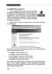
...MSI Live Update Series 2" icon, and the following screen will appear on the update instructions, insert the companion CD and refer to start the update process. Ø Live BIOS - Updates the VGA driver online. Ø Live Utility - To use the function, you purchased does not support any of the screen. MS-6580... ATX Mainboard Live BIOS™/Live Driver™ The Live BIOS™/Live Driver™ is displayed...
...MSI Live Update Series 2" icon, and the following screen will appear on the update instructions, insert the companion CD and refer to start the update process. Ø Live BIOS - Updates the VGA driver online. Ø Live Utility - To use the function, you purchased does not support any of the screen. MS-6580... ATX Mainboard Live BIOS™/Live Driver™ The Live BIOS™/Live Driver™ is displayed...
User Guide
Page 37
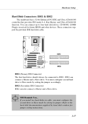
IDE1 can also connect a Master and a Slave drive. Refer to IDE1. These connectors support the provided IDE hard disk cable. MSI Reminds You... Hardware Setup Hard Disk Connectors: IDE1 & IDE2 The mainboard has a 32-bit Enhanced PCI IDE and Ultra ATA66/100 controller that provides PIO ... IDE2 IDE1 (Primary IDE Connector) The first hard drive should always be connected to the hard disk documentation supplied by hard disk vendors for future BIOS) and other devices. You must configure the second drive to Slave mode by setting its jumper. If you install two hard disks on cable, you...
IDE1 can also connect a Master and a Slave drive. Refer to IDE1. These connectors support the provided IDE hard disk cable. MSI Reminds You... Hardware Setup Hard Disk Connectors: IDE1 & IDE2 The mainboard has a 32-bit Enhanced PCI IDE and Ultra ATA66/100 controller that provides PIO ... IDE2 IDE1 (Primary IDE Connector) The first hard drive should always be connected to the hard disk documentation supplied by hard disk vendors for future BIOS) and other devices. You must configure the second drive to Slave mode by setting its jumper. If you install two hard disks on cable, you...
User Guide
Page 46
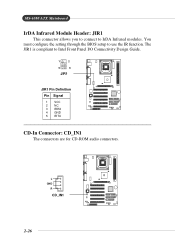
L GND R CD_IN1 2-26 You must configure the setting through the BIOS setup to Intel Front Panel I/O Connectivity Design Guide. 1 2 5 6 JIR1 JIR1 Pin Definition Pin Signal 1 VCC 2 NC 3 IRRX 4 GND 5 IRTX CD-In Connector: CD_IN1 The connectors are for CD-ROM audio connectors. The JIR1 is compliant to use the IR function. MS-6580 ATX Mainboard IrDA Infrared Module Header: JIR1 This connector allows you to connect to IrDA Infrared modules.
L GND R CD_IN1 2-26 You must configure the setting through the BIOS setup to Intel Front Panel I/O Connectivity Design Guide. 1 2 5 6 JIR1 JIR1 Pin Definition Pin Signal 1 VCC 2 NC 3 IRRX 4 GND 5 IRTX CD-In Connector: CD_IN1 The connectors are for CD-ROM audio connectors. The JIR1 is compliant to use the IR function. MS-6580 ATX Mainboard IrDA Infrared Module Header: JIR1 This connector allows you to connect to IrDA Infrared modules.
User Guide
Page 49
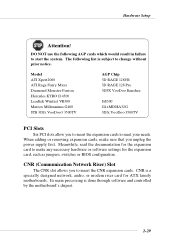
.... CNR is a specially designed network, audio, or modem riser card for the expansion card, such as jumpers, switches or BIOS configuration. When adding or removing expansion cards, make any necessary hardware or software settings for ATX family motherboards. DO NOT use the following list is done through software and controlled by the...
.... CNR is a specially designed network, audio, or modem riser card for the expansion card, such as jumpers, switches or BIOS configuration. When adding or removing expansion cards, make any necessary hardware or software settings for ATX family motherboards. DO NOT use the following list is done through software and controlled by the...
User Guide
Page 51
BIOS Setup BIOS Setup This chapter provides information on the BIOS Setup program and allows you to run the Setup program when: ” An error message appears on the screen during the system booting up, and requests you to change the default settings for optimum use. You may need to run SETUP. ” You want to configure the system for customized features. 3-1 BIOS Setup Chapter 3.
BIOS Setup BIOS Setup This chapter provides information on the BIOS Setup program and allows you to run the Setup program when: ” An error message appears on the screen during the system booting up, and requests you to change the default settings for optimum use. You may need to run SETUP. ” You want to configure the system for customized features. 3-1 BIOS Setup Chapter 3.
User Guide
Page 52
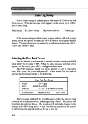
...the message disappears before you respond and you still wish to enter Setup, restart the system by too quickly for you to respond in the BIOS setup utility, so next time when you want to trigger the boot menu. Selecting the First Boot Device You are allowed to enter Setup...1st boot device without entering the BIOS setup utility by using arrow keys and then pressing . Select the one you power on the computer and the system will not make changes to the following. The selection will start POST (Power On Self Test) process. MS-6580 ATX Mainboard Entering Setup Power on...
...the message disappears before you respond and you still wish to enter Setup, restart the system by too quickly for you to respond in the BIOS setup utility, so next time when you want to trigger the boot menu. Selecting the First Boot Device You are allowed to enter Setup...1st boot device without entering the BIOS setup utility by using arrow keys and then pressing . Select the one you power on the computer and the system will not make changes to the following. The selection will start POST (Power On Self Test) process. MS-6580 ATX Mainboard Entering Setup Power on...
User Guide
Page 53
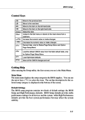
...Load the default CMOS value from Fail-Safe default table, only for the selected setup category is the Main Menu. Default Settings The BIOS setup program contains two kinds of the screen. The on the right-hand side Select the item Jumps to the Exit menu or returns... defaults provide the best system performance but may affect the system stability. 3-3 Main Menu The main menu displays the setup categories the BIOS supplies. BIOS Setup defaults provide stable performance settings for all the CMOS changes and exit Getting Help After entering the Setup utility, the first screen ...
...Load the default CMOS value from Fail-Safe default table, only for the selected setup category is the Main Menu. Default Settings The BIOS setup program contains two kinds of the screen. The on the right-hand side Select the item Jumps to the Exit menu or returns... defaults provide the best system performance but may affect the system stability. 3-3 Main Menu The main menu displays the setup categories the BIOS supplies. BIOS Setup defaults provide stable performance settings for all the CMOS changes and exit Getting Help After entering the Setup utility, the first screen ...
User Guide
Page 54
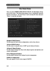
... your settings for basic system configurations, such as time, date etc. Power Management Features Use this menu for power management. Advanced BIOS Features Use this menu to enter the sub-menu. MS-6580 ATX Mainboard The Main Menu Once you enter AMIBIOS NEW SETUP UTILITY, the Main Menu will appear on the screen.
... your settings for basic system configurations, such as time, date etc. Power Management Features Use this menu for power management. Advanced BIOS Features Use this menu to enter the sub-menu. MS-6580 ATX Mainboard The Main Menu Once you enter AMIBIOS NEW SETUP UTILITY, the Main Menu will appear on the screen.
User Guide
Page 55
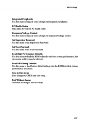
Set Supervisor Password Use this menu to load factory default settings into the BIOS for frequency/voltage control. Load BIOS Setup Defaults Use this menu to set User Password. Save & Exit Setup Save changes to specify your settings for stable system performance operations... Status This entry shows your PC health status. Set User Password Use this menu to load the BIOS values for integrated peripherals. Exit Without Saving Abandon all changes and exit setup. 3-5 BIOS Setup Integrated Peripherals Use this menu to specify your settings for the best system performance, but the ...
Set Supervisor Password Use this menu to load factory default settings into the BIOS for frequency/voltage control. Load BIOS Setup Defaults Use this menu to set User Password. Save & Exit Setup Save changes to specify your settings for stable system performance operations... Status This entry shows your PC health status. Set User Password Use this menu to load the BIOS values for integrated peripherals. Exit Without Saving Abandon all changes and exit setup. 3-5 BIOS Setup Integrated Peripherals Use this menu to specify your settings for the best system performance, but the ...
User Guide
Page 56
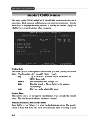
... allows you to set the system time that you prefer. Primary/Secondary IDE Master/Slave Press PgUp/ or PgDn/ to 31 can be keyed by BIOS. month The month from 1 to select the hard disk drive type. System Time This allows you to Sat, determined by numeric function keys. Read-only... can be adjusted by users. The specification of the week, from Sun to set the system to your 3-6 through Dec. date The date from Jan. MS-6580 ATX Mainboard Standard CMOS Features The items inside STANDARD CMOS FEATURES menu are divided into 9 categories.
... allows you to set the system time that you prefer. Primary/Secondary IDE Master/Slave Press PgUp/ or PgDn/ to 31 can be keyed by BIOS. month The month from 1 to select the hard disk drive type. System Time This allows you to Sat, determined by numeric function keys. Read-only... can be adjusted by users. The specification of the week, from Sun to set the system to your 3-6 through Dec. date The date from Jan. MS-6580 ATX Mainboard Standard CMOS Features The items inside STANDARD CMOS FEATURES menu are divided into 9 categories.


