User Manual
Page 12
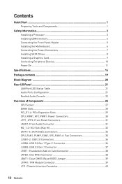
... 3.2 Gen 1 Type-C Connector 36 JUSB3: USB 3.2 Gen 1 Connector 37 JTBT1: Thunderbolt Add-on Card Connector 38 JRTD3: Intel RTD3 Connector 38 JBAT1: Clear CMOS (Reset BIOS) Jumper 39 JTPM1: TPM Module Connector 39 JCI1: Chassis Intrusion Connector 40 12 Contents
... 3.2 Gen 1 Type-C Connector 36 JUSB3: USB 3.2 Gen 1 Connector 37 JTBT1: Thunderbolt Add-on Card Connector 38 JRTD3: Intel RTD3 Connector 38 JBAT1: Clear CMOS (Reset BIOS) Jumper 39 JTPM1: TPM Module Connector 39 JCI1: Chassis Intrusion Connector 40 12 Contents
User Manual
Page 13
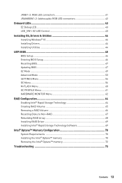
... LED Control 43 Installing OS, Drivers & Utilities 44 Installing Windows® 10 44 Installing Drivers 44 Installing Utilities 44 UEFI BIOS...45 BIOS Setup...46 Entering BIOS Setup 46 Resetting BIOS...47 Updating BIOS...47 EZ Mode...49 Advanced Mode ...53 SETTINGS Menu...54 OC Menu...56 M-FLASH Menu...60 OC PROFILE Menu 61 HARDWARE...
... LED Control 43 Installing OS, Drivers & Utilities 44 Installing Windows® 10 44 Installing Drivers 44 Installing Utilities 44 UEFI BIOS...45 BIOS Setup...46 Entering BIOS Setup 46 Resetting BIOS...47 Updating BIOS...47 EZ Mode...49 Advanced Mode ...53 SETTINGS Menu...54 OC Menu...56 M-FLASH Menu...60 OC PROFILE Menu 61 HARDWARE...
User Manual
Page 14
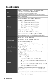
...8729;∙1x DisplayPort port supports a maximum resolution of 4096 x 2304 @ 60Hz ∙∙Supports AMD® 2-Way CrossFire™ Technology Intel® Z490 Chipset ∙∙6x SATA 6Gb/s ports* ∙∙2x M.2 slots (Key M) ▪▪Supports up to intel.com for compatibility information. ...disabled when using Intel® Optane™ memory modules, please ensure that you have updated the drivers and BIOS to the latest version from MSI website. Intel® Z490 Chipset ∙∙4x DDR4 memory slots, support up to 128GB* ∙∙Supports 1R 2133/2666/2933...
...8729;∙1x DisplayPort port supports a maximum resolution of 4096 x 2304 @ 60Hz ∙∙Supports AMD® 2-Way CrossFire™ Technology Intel® Z490 Chipset ∙∙6x SATA 6Gb/s ports* ∙∙2x M.2 slots (Key M) ▪▪Supports up to intel.com for compatibility information. ...disabled when using Intel® Optane™ memory modules, please ensure that you have updated the drivers and BIOS to the latest version from MSI website. Intel® Z490 Chipset ∙∙4x DDR4 memory slots, support up to 128GB* ∙∙Supports 1R 2133/2666/2933...

User Manual
Page 16
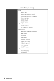
x 9.6 in . Continued from previous page Internal Connectors LED Features I/O Controller Hardware Monitor Form Factor BIOS Features ∙∙1x 24-pin ATX main power connector ∙∙1x 8-pin ATX 12V power connector ∙∙1x 4-pin ATX 12V power ... speed control ∙∙ATX Form Factor ∙∙12 in . (30.5 cm x 24.4 cm) ∙∙1x 256 Mb flash ∙∙UEFI AMI BIOS ∙∙ACPI 6.2, SM BIOS 3.2 ∙∙ Multi-language Continued on next page 16 Specifications
x 9.6 in . Continued from previous page Internal Connectors LED Features I/O Controller Hardware Monitor Form Factor BIOS Features ∙∙1x 24-pin ATX main power connector ∙∙1x 8-pin ATX 12V power connector ∙∙1x 4-pin ATX 12V power ... speed control ∙∙ATX Form Factor ∙∙12 in . (30.5 cm x 24.4 cm) ∙∙1x 256 Mb flash ∙∙UEFI AMI BIOS ∙∙ACPI 6.2, SM BIOS 3.2 ∙∙ Multi-language Continued on next page 16 Specifications
User Manual
Page 18
... ▪▪Pre-installed IO shielding ∙∙ Performance ▪▪Multi GPU-CrossFire Technology ▪▪DDR4 Boost ▪▪Core Boost ▪▪GAME Boost ▪▪Lightning USB 20G ▪▪USB 3.2 Gen 2 10G ▪▪USB with type A+C ▪▪Front USB Type-C ▪▪Dual CPU...
... ▪▪Pre-installed IO shielding ∙∙ Performance ▪▪Multi GPU-CrossFire Technology ▪▪DDR4 Boost ▪▪Core Boost ▪▪GAME Boost ▪▪Lightning USB 20G ▪▪USB 3.2 Gen 2 10G ▪▪USB with type A+C ▪▪Front USB Type-C ▪▪Dual CPU...

User Manual
Page 26
... JUSB1~2 JUSB3 JUSB4 LED_SW1 M2_1~2 PCI_E1~4 SATA1~6 Port Type Fan Connectors Power Connectors LGA 1200 CPU Socket Memory slots Front Audio Connector Clear CMOS (Reset BIOS) Jumper Chassis Intrusion Connector Front Panel Connectors Addressable RGB LED connectors RGB LED connectors Intel RTD3 Connector Thunderbolt Add-on Card Connector TPM Module Connector...
... JUSB1~2 JUSB3 JUSB4 LED_SW1 M2_1~2 PCI_E1~4 SATA1~6 Port Type Fan Connectors Power Connectors LGA 1200 CPU Socket Memory slots Front Audio Connector Clear CMOS (Reset BIOS) Jumper Chassis Intrusion Connector Front Panel Connectors Addressable RGB LED connectors RGB LED connectors Intel RTD3 Connector Thunderbolt Add-on Card Connector TPM Module Connector...
User Manual
Page 28
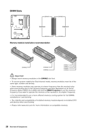
... may operate at a higher frequency. ∙∙It is recommended to the memory frequency operates dependent on compatible memory. 28 Overview of Components Go to BIOS and find the DRAM Frequency to set the memory frequency if you want to operate the memory at the marked or at a lower frequency than... or overclocking. ∙∙The stability and compatibility of installed memory module depend on installed CPU and devices when overclocking. ∙∙Please refer www.msi.com for more information on its Serial Presence Detect (SPD).
... may operate at a higher frequency. ∙∙It is recommended to the memory frequency operates dependent on compatible memory. 28 Overview of Components Go to BIOS and find the DRAM Frequency to set the memory frequency if you want to operate the memory at the marked or at a lower frequency than... or overclocking. ∙∙The stability and compatibility of installed memory module depend on installed CPU and devices when overclocking. ∙∙Please refer www.msi.com for more information on its Serial Presence Detect (SPD).

User Manual
Page 35
... 4 Speed Control Signal DC Mode pin definition 1 Ground 2 Voltage Control 3 Sense 4 NC Overview of the fan speed that allow you to adjust fan speed in BIOS > HARDWARE MONITOR. DC Mode fan connectors control fan speed by changing voltage. Select PWM mode or DC mode There are gradient points of Components 35...
... 4 Speed Control Signal DC Mode pin definition 1 Ground 2 Voltage Control 3 Sense 4 NC Overview of the fan speed that allow you to adjust fan speed in BIOS > HARDWARE MONITOR. DC Mode fan connectors control fan speed by changing voltage. Select PWM mode or DC mode There are gradient points of Components 35...

User Manual
Page 39
... system configuration, set the jumper to save system configuration data. JTPM1: TPM Module Connector This connector is external powered from JBAT1. 4. JBAT1: Clear CMOS (Reset BIOS) Jumper There is CMOS memory onboard that is for more details and usages. 2 12 1 11 1 SPI Power 2 SPI Chip Select 3 Master In Slave Out (SPI... JBAT1 for about 5-10 seconds. 3. Use a jumper cap to the TPM security platform manual for TPM (Trusted Platform Module). Keep Data (default) Clear CMOS/ Reset BIOS Resetting BIOS to default values 1. Power off the computer and unplug the power cord 2.
... system configuration, set the jumper to save system configuration data. JTPM1: TPM Module Connector This connector is external powered from JBAT1. 4. JBAT1: Clear CMOS (Reset BIOS) Jumper There is CMOS memory onboard that is for more details and usages. 2 12 1 11 1 SPI Power 2 SPI Chip Select 3 Master In Slave Out (SPI... JBAT1 for about 5-10 seconds. 3. Use a jumper cap to the TPM security platform manual for TPM (Trusted Platform Module). Keep Data (default) Clear CMOS/ Reset BIOS Resetting BIOS to default values 1. Power off the computer and unplug the power cord 2.

User Manual
Page 40
... press the Enter key to the chassis intrusion switch/ sensor on . Resetting the chassis intrusion warning 1. JCI1: Chassis Intrusion Connector This connector allows you to BIOS > SETTINGS > Security > Chassis Intrusion Configuration. 4. Once the chassis cover is opened again, a warning message will be displayed on screen when the computer is turned on... Yes. 6. Normal (default) Trigger the chassis intrusion event Using chassis intrusion detector 1. Press F10 to save and exit and then press the Enter key to BIOS > SETTINGS > Security > Chassis Intrusion Configuration. 2.
... press the Enter key to the chassis intrusion switch/ sensor on . Resetting the chassis intrusion warning 1. JCI1: Chassis Intrusion Connector This connector allows you to BIOS > SETTINGS > Security > Chassis Intrusion Configuration. 4. Once the chassis cover is opened again, a warning message will be displayed on screen when the computer is turned on... Yes. 6. Normal (default) Trigger the chassis intrusion event Using chassis intrusion detector 1. Press F10 to save and exit and then press the Enter key to BIOS > SETTINGS > Security > Chassis Intrusion Configuration. 2.

User Manual
Page 45
... Incompatible UEFI cases ∙∙ 32-bit Windows operating system - The MSI UEFI BIOS uses UEFI as the default boot mode to CSM mode during the transition. ⚠⚠Important The term BIOS in this user guide refers to ensure that you to replace legacy devices ...the operating system to UEFI BIOS unless otherwise noted. CPU Temperature: Motherboard Temperature: VCore: DDR Voltage: BIOS Mode: CSM/UEFI UEFI boot mode CPU Temperature: Motherboard Temperature: VCore: DDR Voltage: BIOS Mode: CSM/UEFI CSM boot mode UEFI BIOS 45 UEFI BIOS MSI UEFI BIOS is no malware tampers with...
... Incompatible UEFI cases ∙∙ 32-bit Windows operating system - The MSI UEFI BIOS uses UEFI as the default boot mode to CSM mode during the transition. ⚠⚠Important The term BIOS in this user guide refers to ensure that you to replace legacy devices ...the operating system to UEFI BIOS unless otherwise noted. CPU Temperature: Motherboard Temperature: VCore: DDR Voltage: BIOS Mode: CSM/UEFI UEFI boot mode CPU Temperature: Motherboard Temperature: VCore: DDR Voltage: BIOS Mode: CSM/UEFI CSM boot mode UEFI BIOS 45 UEFI BIOS MSI UEFI BIOS is no malware tampers with...

User Manual
Page 46
... settings to avoid possible system damage or failure booting unless you press F10, a confirmation window appears and it to the HELP information panel for BIOS item description. ∙∙The pictures in normal conditions. Function key F1: General Help list F2: Add/ Remove a favorite item F3: ...Menu message appears on the screen during the boot process. Ctrl+F: Enter Search page * When you are familiar with the processor. BIOS Setup The default settings offer the optimal performance for system stability in this chapter are for reference only and may be for reference only.
... settings to avoid possible system damage or failure booting unless you press F10, a confirmation window appears and it to the HELP information panel for BIOS item description. ∙∙The pictures in normal conditions. Function key F1: General Help list F2: Add/ Remove a favorite item F3: ...Menu message appears on the screen during the boot process. Ctrl+F: Enter Search page * When you are familiar with the processor. BIOS Setup The default settings offer the optimal performance for system stability in this chapter are for reference only and may be for reference only.

User Manual
Page 47
...from MSI website. Updating BIOS: 1. UEFI BIOS 47 Updating BIOS Updating BIOS with M-FLASH Before updating: Please download the latest BIOS file that contains the update file into the USB flash drive. When prompted click on Yes to perform the BIOS update process. 4. Select a BIOS file to start recovering BIOS. ...5. Please refer to reboot the system. And then save the BIOS file into the USB port. 2. Please refer the following methods to ...
...from MSI website. Updating BIOS: 1. UEFI BIOS 47 Updating BIOS Updating BIOS with M-FLASH Before updating: Please download the latest BIOS file that contains the update file into the USB flash drive. When prompted click on Yes to perform the BIOS update process. 4. Select a BIOS file to start recovering BIOS. ...5. Please refer to reboot the system. And then save the BIOS file into the USB port. 2. Please refer the following methods to ...

User Manual
Page 48
... on Download icon to search the latest BIOS file. 4. Select the BIOS file and click on Advance button. 3. And then click Next and Start to Support page. 2. Install and launch MSI DRAGON CENTER and go to start updating BIOS. 6. Click Next and choose In Windows mode. Updating BIOS: 1. Click on Scan button to download and...
... on Download icon to search the latest BIOS file. 4. Select the BIOS file and click on Advance button. 3. And then click Next and Start to Support page. 2. Install and launch MSI DRAGON CENTER and go to start updating BIOS. 6. Click Next and choose In Windows mode. Updating BIOS: 1. Click on Scan button to download and...

User Manual
Page 49
... you to search by pressing the Setup Mode switch or F7 function key. To configure the advanced BIOS settings, please enter the Advanced Mode by BIOS item name. XMP Profile GAME BOOST Component Information Screenshot Setup Mode switch Search Language System information Boot device priority bar M-Flash Favorites ...overclocking. click on it provides the basic system information and allows you to configure the basic setting. UEFI BIOS 49 EZ Mode At EZ mode, it to toggle the GAME BOOST for memory to overclock. press this tab or the F12 key to take a screenshot and save ...
... you to search by pressing the Setup Mode switch or F7 function key. To configure the advanced BIOS settings, please enter the Advanced Mode by BIOS item name. XMP Profile GAME BOOST Component Information Screenshot Setup Mode switch Search Language System information Boot device priority bar M-Flash Favorites ...overclocking. click on it provides the basic system information and allows you to configure the basic setting. UEFI BIOS 49 EZ Mode At EZ mode, it to toggle the GAME BOOST for memory to overclock. press this tab or the F12 key to take a screenshot and save ...

User Manual
Page 50
... low is enabled when the button shows ON . ⚠⚠Important The function buttons will vary with the motherboard you to show the information of BIOS setup. ∙∙ System information - enable or disable these functions by clicking on the CPU, Memory, Storage, Fan Info and Help buttons to select ... ∙∙ Component Information - The function is left to change the boot priority. ∙∙ Language - click on these buttons. allows you purchased. 50 UEFI BIOS shows the CPU/ DDR speed, CPU/ MB temperature, MB/ CPU type, memory size, CPU/ DDR voltage...
... low is enabled when the button shows ON . ⚠⚠Important The function buttons will vary with the motherboard you to show the information of BIOS setup. ∙∙ System information - enable or disable these functions by clicking on the CPU, Memory, Storage, Fan Info and Help buttons to select ... ∙∙ Component Information - The function is left to change the boot priority. ∙∙ Language - click on these buttons. allows you purchased. 50 UEFI BIOS shows the CPU/ DDR speed, CPU/ MB temperature, MB/ CPU type, memory size, CPU/ DDR voltage...

User Manual
Page 51
...menu that allows you can save and access favorite/ frequently-used BIOS setting items. ▪▪To add a BIOS item to show the Favorites window. Choose a favorite page and click on search page. 2. Select a BIOS item not only on BIOS menu but also on OK. It provides 5 menus for you ...to create personal BIOS menu where you to update BIOS with a USB flash drive. ∙∙ Hardware Monitor - ∙∙ M-Flash -...
...menu that allows you can save and access favorite/ frequently-used BIOS setting items. ▪▪To add a BIOS item to show the Favorites window. Choose a favorite page and click on search page. 2. Select a BIOS item not only on BIOS menu but also on OK. It provides 5 menus for you ...to create personal BIOS menu where you to update BIOS with a USB flash drive. ∙∙ Hardware Monitor - ∙∙ M-Flash -...

User Manual
Page 52
Choose Delete and click on favorite menu. 2. ▪▪To delete a BIOS item from favorite menu 1. Select a BIOS item on OK. 52 UEFI BIOS Right-click or press F2 key. 3.
Choose Delete and click on favorite menu. 2. ▪▪To delete a BIOS item from favorite menu 1. Select a BIOS item on OK. 52 UEFI BIOS Right-click or press F2 key. 3.

User Manual
Page 53
...parameters for chipset and boot devices. ▪▪OC - allows you to adjust the frequency and voltage. provides BIOS setting items and information to update BIOS with a USB flash drive. ▪▪OC PROFILE - Advanced Mode Press Setup Mode switch or F7 function ...key can switch between EZ Mode and Advanced Mode in BIOS setup. allows you to manage overclocking profiles. ▪▪HARDWARE MONITOR - BIOS menu selection BIOS menu selection Menu display ∙∙ BIOS menu selection - provides the information of system. ▪▪BOARD EXPLORER...
...parameters for chipset and boot devices. ▪▪OC - allows you to adjust the frequency and voltage. provides BIOS setting items and information to update BIOS with a USB flash drive. ▪▪OC PROFILE - Advanced Mode Press Setup Mode switch or F7 function ...key can switch between EZ Mode and Advanced Mode in BIOS setup. allows you to manage overclocking profiles. ▪▪HARDWARE MONITOR - BIOS menu selection BIOS menu selection Menu display ∙∙ BIOS menu selection - provides the information of system. ▪▪BOARD EXPLORER...

User Manual
Page 54
... SATA/ M.2 cable and power cable connections of the device and motherboard. ▶▶System Information Shows detailed system information, including CPU type, BIOS version, and Memory (read only). ▶▶DMI Information Shows system information, desktop Board Information and chassis Information. (Read only). ▶&#...week, from Sun to 31 can be keyed by numeric function keys. This sub-menu is . The year can be adjusted by BIOS. through Dec. Use tab key to switch between date elements. SETTINGS Menu This menu allows you to specify the parameters for system,...
... SATA/ M.2 cable and power cable connections of the device and motherboard. ▶▶System Information Shows detailed system information, including CPU type, BIOS version, and Memory (read only). ▶▶DMI Information Shows system information, desktop Board Information and chassis Information. (Read only). ▶&#...week, from Sun to 31 can be keyed by numeric function keys. This sub-menu is . The year can be adjusted by BIOS. through Dec. Use tab key to switch between date elements. SETTINGS Menu This menu allows you to specify the parameters for system,...


