
User Manual
Page 1
... the URL to watch it with the web browser on your computer. Some of Screws Quick Start 1 Quick Start Thank you for purchasing the MSI® MPG Z490 GAMING CARBON WIFI motherboard. Preparing Tools and Components Intel® LGA 1200 CPU CPU Fan DDR4 Memory Power Supply Unit Chassis Graphics Card Thermal Paste SATA Hard Disk Drive...
... the URL to watch it with the web browser on your computer. Some of Screws Quick Start 1 Quick Start Thank you for purchasing the MSI® MPG Z490 GAMING CARBON WIFI motherboard. Preparing Tools and Components Intel® LGA 1200 CPU CPU Fan DDR4 Memory Power Supply Unit Chassis Graphics Card Thermal Paste SATA Hard Disk Drive...

User Manual
Page 2
... discharge (ESD). Safety Information ∙∙The components included in an electrostatic shielding container or on an anti-static pad whenever the motherboard is not installed. ∙∙Before turning on the computer, ensure that all components are securely connected. If an ESD wrist strap... is not available, discharge yourself of breakage. ∙∙Do not leave this motherboard away from humidity. ∙∙Make sure that your electrical outlet provides the same voltage as is indicated on the PSU, before ...
... discharge (ESD). Safety Information ∙∙The components included in an electrostatic shielding container or on an anti-static pad whenever the motherboard is not installed. ∙∙Before turning on the computer, ensure that all components are securely connected. If an ESD wrist strap... is not available, discharge yourself of breakage. ∙∙Do not leave this motherboard away from humidity. ∙∙Make sure that your electrical outlet provides the same voltage as is indicated on the PSU, before ...

User Manual
Page 6
Installing the Motherboard 1 Torque: 3 kgf·cm* 2 BAT1 *3 kgf·cm = 0.3 N·m = 2.6 lbf·in 6 Quick Start
Installing the Motherboard 1 Torque: 3 kgf·cm* 2 BAT1 *3 kgf·cm = 0.3 N·m = 2.6 lbf·in 6 Quick Start

User Manual
Page 12
Contents Quick Start ...1 Preparing Tools and Components 1 Safety Information 2 Installing a Processor 3 Installing DDR4 memory 4 Connecting the Front Panel Header 5 Installing the Motherboard 6 Connecting the Power Connectors 7 Installing SATA Drives 8 Installing a Graphics Card 9 Connecting Peripheral Devices 10 Power On...11 Specifications...14 JCORSAIR1 Connector Specification 19 Package contents ...
Contents Quick Start ...1 Preparing Tools and Components 1 Safety Information 2 Installing a Processor 3 Installing DDR4 memory 4 Connecting the Front Panel Header 5 Installing the Motherboard 6 Connecting the Power Connectors 7 Installing SATA Drives 8 Installing a Graphics Card 9 Connecting Peripheral Devices 10 Power On...11 Specifications...14 JCORSAIR1 Connector Specification 19 Package contents ...

User Manual
Page 20
It should contain: Motherboard MPG Z490 GAMING CARBON WIFI SATA 6G cables (2 cables/pack) 1 LED JRGB Y cable 1 Cable LED JCORSAIR cable 1 LED JRAINBOW cable 1 Wi-Fi Antenna 1 M.2 screws (3 pcs./pack) 1 Accessories Case Badge 1 SATA cable stickers 1 Product registration card 1 Application Driver DVD 1 User manual 1 Documentation Quick installation guide 1 ⚠⚠Important If any of your retailer. 20 Package contents Package contents Please check the contents of the above items are damaged or missing, please contact your motherboard package.
It should contain: Motherboard MPG Z490 GAMING CARBON WIFI SATA 6G cables (2 cables/pack) 1 LED JRGB Y cable 1 Cable LED JCORSAIR cable 1 LED JRAINBOW cable 1 Wi-Fi Antenna 1 M.2 screws (3 pcs./pack) 1 Accessories Case Badge 1 SATA cable stickers 1 Product registration card 1 Application Driver DVD 1 User manual 1 Documentation Quick installation guide 1 ⚠⚠Important If any of your retailer. 20 Package contents Package contents Please check the contents of the above items are damaged or missing, please contact your motherboard package.

User Manual
Page 28
.... ∙∙Confirm that all other system components can seriously damage the CPU and motherboard. A CPU heatsink is not recommended. MSI will deal with Return Merchandise Authorization (RMA) requests if only the motherboard comes with the protective cap on the CPU socket. ∙∙When installing a ... The surface of the LGA 1200 CPU has two notches and a golden triangle to assist in the heatsink/ cooler package for motherboard placement. MSI® does not guarantee the damages or risks caused by covering the socket with the CPU before installing or removing the CPU....
.... ∙∙Confirm that all other system components can seriously damage the CPU and motherboard. A CPU heatsink is not recommended. MSI will deal with Return Merchandise Authorization (RMA) requests if only the motherboard comes with the protective cap on the CPU socket. ∙∙When installing a ... The surface of the LGA 1200 CPU has two notches and a golden triangle to assist in the heatsink/ cooler package for motherboard placement. MSI® does not guarantee the damages or risks caused by covering the socket with the CPU before installing or removing the CPU....

User Manual
Page 33
... cable at a 90-degree angle. However, it is recommended that the flat connector be connected to one SATA device. Each connector can connect to the motherboard for space saving purposes. ∙∙SATA2 will be unavailable when installing M.2 SATA SSD in the M2_1 slot. ∙∙SATA5 & SATA6 will be unavailable...
... cable at a 90-degree angle. However, it is recommended that the flat connector be connected to one SATA device. Each connector can connect to the motherboard for space saving purposes. ∙∙SATA2 will be unavailable when installing M.2 SATA SSD in the M2_1 slot. ∙∙SATA5 & SATA6 will be unavailable...

User Manual
Page 35
Overview of the motherboard. ∙ It is recommended to connect two CPU power connectors (CPU_PWR1 and CPU_PWR2) to ensure stable operation of Components 35 CPU_PWR1~2, ATX_PWR1: Power Connectors These ...;∙Make sure that all the power cables are securely connected to a proper ATX power supply to optimize system stability for OC and prevent the motherboard from overheating under heavy load.
Overview of the motherboard. ∙ It is recommended to connect two CPU power connectors (CPU_PWR1 and CPU_PWR2) to ensure stable operation of Components 35 CPU_PWR1~2, ATX_PWR1: Power Connectors These ...;∙Make sure that all the power cables are securely connected to a proper ATX power supply to optimize system stability for OC and prevent the motherboard from overheating under heavy load.
User Manual
Page 40
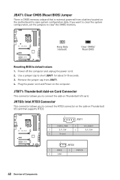
... supports RTD3. 1 JTBT1 1 FORCE_PWR 2 3 SLP_S3# 4 5 Ground SCI_EVENT SLP_S5# 1 JRTD3 1 WAKE 2 PWR EN 3 GND 40 Overview of Components If you to connect the add-on the motherboard to clear the CMOS memory. Use a jumper cap to default values 1. JTBT1: Thunderbolt Add-on Card Connector This connector allows you want to clear the...
... supports RTD3. 1 JTBT1 1 FORCE_PWR 2 3 SLP_S3# 4 5 Ground SCI_EVENT SLP_S5# 1 JRTD3 1 WAKE 2 PWR EN 3 GND 40 Overview of Components If you to connect the add-on the motherboard to clear the CMOS memory. Use a jumper cap to default values 1. JTBT1: Thunderbolt Add-on Card Connector This connector allows you want to clear the...

User Manual
Page 43
... series. 1 > 2 > 3 > 4 > 5 > 6. Please refer to connect the CORSAIR Individually Addressable Lighting PRO RGB LED strips 5V or CORSAIR RGB fans with MSI's software. JCORSAIR1 1 1 +5V 2 3 Ground Data CORSAIR RGB Fan Connection CORSAIR RGB LED fan SATA power SYS_FAN SYS_FAN CORSAIR fan hub 4 5 6 SYS_FAN 3 2 ...Fans or RGB LED Lighting PRO strips supported may differ between models. Once all items are connected properly, you to the motherboard specification. ∙∙CORSAIR RGB LED Fan and CORSAIR Lighting Node PRO can control the CORSAIR RGB LED strips and fans...
... series. 1 > 2 > 3 > 4 > 5 > 6. Please refer to connect the CORSAIR Individually Addressable Lighting PRO RGB LED strips 5V or CORSAIR RGB fans with MSI's software. JCORSAIR1 1 1 +5V 2 3 Ground Data CORSAIR RGB Fan Connection CORSAIR RGB LED fan SATA power SYS_FAN SYS_FAN CORSAIR fan hub 4 5 6 SYS_FAN 3 2 ...Fans or RGB LED Lighting PRO strips supported may differ between models. Once all items are connected properly, you to the motherboard specification. ∙∙CORSAIR RGB LED Fan and CORSAIR Lighting Node PRO can control the CORSAIR RGB LED strips and fans...

User Manual
Page 44
LED_SW1: EZ LED Control This switch is not detected or fail. BOOT - VGA - indicates the booting device is used to switch on/ off all the LEDs of motherboard. DRAM - indicates GPU is not detected or fail. EZ Debug LED These LEDs indicate the debug status of Components indicates DRAM is not detected or fail. CPU - indicates CPU is not detected or fail. LED_OFF LED_SW1 LED_ON (Default) 44 Overview of the motherboard.
LED_SW1: EZ LED Control This switch is not detected or fail. BOOT - VGA - indicates the booting device is used to switch on/ off all the LEDs of motherboard. DRAM - indicates GPU is not detected or fail. EZ Debug LED These LEDs indicate the debug status of Components indicates DRAM is not detected or fail. CPU - indicates CPU is not detected or fail. LED_OFF LED_SW1 LED_ON (Default) 44 Overview of the motherboard.
User Manual
Page 46
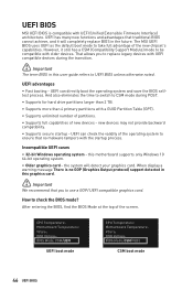
...After entering the BIOS, find the BIOS Mode at the top of the new chipset's capabilities. this motherboard supports only Windows 10 64-bit operating system. ∙∙ Older graphics card - The MSI UEFI BIOS uses UEFI as the default boot mode to CSM mode during the transition. ⚠⚠...8729;∙ 32-bit Windows operating system - How to be compatible with older devices. However, it will detect your graphics card. UEFI BIOS MSI UEFI BIOS is no malware tampers with the startup process. the system will completely replace BIOS in this user guide refers to use a GOP/ ...
...After entering the BIOS, find the BIOS Mode at the top of the new chipset's capabilities. this motherboard supports only Windows 10 64-bit operating system. ∙∙ Older graphics card - The MSI UEFI BIOS uses UEFI as the default boot mode to CSM mode during the transition. ⚠⚠...8729;∙ 32-bit Windows operating system - How to be compatible with older devices. However, it will detect your graphics card. UEFI BIOS MSI UEFI BIOS is no malware tampers with the startup process. the system will completely replace BIOS in this user guide refers to use a GOP/ ...
User Manual
Page 48
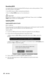
... flash mode. ▪▪Reboot and press Ctrl + F5 key during POST to reboot the system. 3. Insert the USB flash drive that matches your motherboard model from MSI website. Resetting BIOS You might need to restore the default BIOS setting to solve certain problems. There are several ways to reset BIOS: ∙... jumper on Yes to the Clear CMOS jumper section for BIOS update. ▪▪Reboot and press Del key during POST and click on the motherboard. ⚠⚠Important Be sure the computer is 100% completed, the system will reboot automatically. 48 UEFI BIOS
... flash mode. ▪▪Reboot and press Ctrl + F5 key during POST to reboot the system. 3. Insert the USB flash drive that matches your motherboard model from MSI website. Resetting BIOS You might need to restore the default BIOS setting to solve certain problems. There are several ways to reset BIOS: ∙... jumper on Yes to the Clear CMOS jumper section for BIOS update. ▪▪Reboot and press Del key during POST and click on the motherboard. ⚠⚠Important Be sure the computer is 100% completed, the system will reboot automatically. 48 UEFI BIOS
User Manual
Page 50
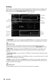
click on it to toggle the GAME BOOST for memory to overclock. This function is only available when both of the motherboard and CPU are supporting this function. ⚠⚠Important Please don't make any changes in OC menu and don't load defaults to keep the ...optimal performance and system stability after activating the GAME BOOST function. ∙∙ XMP Profile - It allows ...
click on it to toggle the GAME BOOST for memory to overclock. This function is only available when both of the motherboard and CPU are supporting this function. ⚠⚠Important Please don't make any changes in OC menu and don't load defaults to keep the ...optimal performance and system stability after activating the GAME BOOST function. ∙∙ XMP Profile - It allows ...
User Manual
Page 51
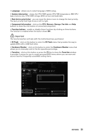
... left to change the boot priority. click on this button to enter the Hardware Monitor menu that provides the way to update BIOS with the motherboard you to manually control the fan speed by clicking on this button to show the Favorites window. click on the CPU, Memory, Storage, Fan Info...
... left to change the boot priority. click on this button to enter the Hardware Monitor menu that provides the way to update BIOS with the motherboard you to manually control the fan speed by clicking on this button to show the Favorites window. click on the CPU, Memory, Storage, Fan Info...
User Manual
Page 53
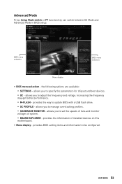
... the frequency may get better performance. ▪▪M-FLASH - allows you to set the speeds of fans and monitor voltages of installed devices on this motherboard. ∙∙ Menu display - provides BIOS setting items and information to update BIOS with a USB flash drive. ▪▪OC PROFILE - BIOS menu selection BIOS...
... the frequency may get better performance. ▪▪M-FLASH - allows you to set the speeds of fans and monitor voltages of installed devices on this motherboard. ∙∙ Menu display - provides BIOS setting items and information to update BIOS with a USB flash drive. ▪▪OC PROFILE - BIOS menu selection BIOS...
User Manual
Page 54
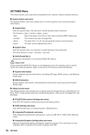
...;Important If the connected SATA/ M.2 device is not displayed, turn off computer and re-check SATA/ M.2 cable and power cable connections of the device and motherboard. ▶▶System Information Shows detailed system information, including CPU type, BIOS version, and Memory (read only). ▶▶DMI Information Shows system information, desktop...
...;Important If the connected SATA/ M.2 device is not displayed, turn off computer and re-check SATA/ M.2 cable and power cable connections of the device and motherboard. ▶▶System Information Shows detailed system information, including CPU type, BIOS version, and Memory (read only). ▶▶DMI Information Shows system information, desktop...

User Manual
Page 60
.... Click on Yes to update BIOS with a USB flash drive. Select a BIOS file to update BIOS. 1. Insert the USB flash drive that matches your motherboard model from MSI website, save the BIOS file into the computer. 2. The system will enter the flash mode and a file selection menu will appear after rebooting. 4. And...
.... Click on Yes to update BIOS with a USB flash drive. Select a BIOS file to update BIOS. 1. Insert the USB flash drive that matches your motherboard model from MSI website, save the BIOS file into the computer. 2. The system will enter the flash mode and a file selection menu will appear after rebooting. 4. And...

User Manual
Page 63
UEFI BIOS 63 Click and drag the duty points to display the fan duty curve line (yellow) in this section are for reference only and may vary from the motherboard you want to adjust and to adjust the fan speed. Select a fan to be adjusted Duty points ⚠⚠Important The pictures in fan operating windows. 2. Selects a fan that you purchased. Adjusting fans 1.
UEFI BIOS 63 Click and drag the duty points to display the fan duty curve line (yellow) in this section are for reference only and may vary from the motherboard you want to adjust and to adjust the fan speed. Select a fan to be adjusted Duty points ⚠⚠Important The pictures in fan operating windows. 2. Selects a fan that you purchased. Adjusting fans 1.

User Manual
Page 70
...Install the Intel® Rapid Storage Technology 16. 1. Install the Intel® Rapid Storage Technology ▫▫Reboot to operating system. ▫▫Insert the MSI Drive Disk into the M.2 slot. 3. If you turn off the system. ▫▫Refer to the Specifications for location to install your Intel® ...Configuration This section describes how to install and remove the Intel® Optane™ memory. System Requirements ∙∙Intel® Optane™ memory ready MSI® motherboards ∙∙Supported 8th Gen, or later, Intel® Core™ -
...Install the Intel® Rapid Storage Technology 16. 1. Install the Intel® Rapid Storage Technology ▫▫Reboot to operating system. ▫▫Insert the MSI Drive Disk into the M.2 slot. 3. If you turn off the system. ▫▫Refer to the Specifications for location to install your Intel® ...Configuration This section describes how to install and remove the Intel® Optane™ memory. System Requirements ∙∙Intel® Optane™ memory ready MSI® motherboards ∙∙Supported 8th Gen, or later, Intel® Core™ -


