
User Manual
Page 13
... CPU_FAN1, PUMP_FAN1, SYS_FAN1~4: Fan Connectors 37 JAUD1: Front Audio Connector 38 JCI1: Chassis Intrusion Connector 38 JTPM1: TPM Module Connector 39 JBAT1: Clear CMOS (Reset BIOS) Jumper 39 Contents 13
... CPU_FAN1, PUMP_FAN1, SYS_FAN1~4: Fan Connectors 37 JAUD1: Front Audio Connector 38 JCI1: Chassis Intrusion Connector 38 JTPM1: TPM Module Connector 39 JBAT1: Clear CMOS (Reset BIOS) Jumper 39 Contents 13
User Manual
Page 14
... demonstration power input connector 43 Installing OS, Drivers & Utilities 44 Installing Windows® 10 44 Installing Drivers 44 Installing Utilities 44 BIOS Setup ...45 Entering BIOS Setup 45 Resetting BIOS...46 Updating BIOS...46 EZ Mode ...48 Advanced Mode ...50 SETTINGS...51 Advanced...51 Boot...56 Security ...57 Save & Exit...58 OC...59 M-FLASH...
... demonstration power input connector 43 Installing OS, Drivers & Utilities 44 Installing Windows® 10 44 Installing Drivers 44 Installing Utilities 44 BIOS Setup ...45 Entering BIOS Setup 45 Resetting BIOS...46 Updating BIOS...46 EZ Mode ...48 Advanced Mode ...50 SETTINGS...51 Advanced...51 Boot...56 Security ...57 Save & Exit...58 OC...59 M-FLASH...

User Manual
Page 19
... y 1x HDMI port y 2x WiFi/ Bluetooth antenna jacks y 1x LAN(RJ45) port y 3x USB 3.2 Gen2 Type A ports y 1x USB 3.2 Gen2 Type C port y 5x OFC audio jacks y 1x Optical S/PDIF Out connector y 1x 256 Mb flash y UEFI AMI BIOS y ACPI 6.1, SM BIOS 2.8 y Multi-language y Drivers y DRAGON CENTER y Nahimic Audio y CPU-Z MSI GAMING y MSI App Player (BlueStacks) y Google...
... y 1x HDMI port y 2x WiFi/ Bluetooth antenna jacks y 1x LAN(RJ45) port y 3x USB 3.2 Gen2 Type A ports y 1x USB 3.2 Gen2 Type C port y 5x OFC audio jacks y 1x Optical S/PDIF Out connector y 1x 256 Mb flash y UEFI AMI BIOS y ACPI 6.1, SM BIOS 2.8 y Multi-language y Drivers y DRAGON CENTER y Nahimic Audio y CPU-Z MSI GAMING y MSI App Player (BlueStacks) y Google...

User Manual
Page 21
...GPU-CrossFire Technology ƒ DDR4 Boost ƒ Core Boost ƒ GAME Boost ƒ USB with type A+C ƒ AMD Turbo USB 3.2 Gen 2 ƒ Dual CPU Power y Gamer Experience ƒ DRAGON CENTER ƒ GAMING HOTKEY ƒ GAMING MOUSE Control ƒ USB SPEED UP ƒ Total Fan control ...ƒ Live Update ƒ APP Player y BIOS ƒ Click BIOS 5 ƒ Flash BIOS Button JCORSAIR1 Connector Specification Supporting CORSAIR RGB Products Lighting Node PRO LED Strip HD120 RGB Fan...
...GPU-CrossFire Technology ƒ DDR4 Boost ƒ Core Boost ƒ GAME Boost ƒ USB with type A+C ƒ AMD Turbo USB 3.2 Gen 2 ƒ Dual CPU Power y Gamer Experience ƒ DRAGON CENTER ƒ GAMING HOTKEY ƒ GAMING MOUSE Control ƒ USB SPEED UP ƒ Total Fan control ...ƒ Live Update ƒ APP Player y BIOS ƒ Click BIOS 5 ƒ Flash BIOS Button JCORSAIR1 Connector Specification Supporting CORSAIR RGB Products Lighting Node PRO LED Strip HD120 RGB Fan...

User Manual
Page 24
... ● Line-Out/ Front Speaker Out Mic In (●: connected, Blank: empty) 24 Rear I /O Panel PS/2 Wi-Fi Antenna connectors USB 3.2 Gen1 LAN Type-A Flash BIOS Button & Port Audio Ports USB 2.0 Type-A USB 3.2 Gen2 Type-C Optical S/PDIF-Out USB 3.2 Gen2 Type-A USB 3.2 Gen2 Type-A y Flash...
... ● Line-Out/ Front Speaker Out Mic In (●: connected, Blank: empty) 24 Rear I /O Panel PS/2 Wi-Fi Antenna connectors USB 3.2 Gen1 LAN Type-A Flash BIOS Button & Port Audio Ports USB 2.0 Type-A USB 3.2 Gen2 Type-C Optical S/PDIF-Out USB 3.2 Gen2 Type-A USB 3.2 Gen2 Type-A y Flash...

User Manual
Page 29
... Port Type CPU_FAN1, PUMP_FAN1, SYS_FAN1~4 Fan Connectors CPU_PWR1~2, ATX_PWR1 Power Connectors DIMMA1/A2/B1/B2 DIMM Slots JAUD1 Front Audio Connector JBAT1 Clear CMOS (Reset BIOS) Jumper JCI1 Chassis Intrusion Connector JCORSAIR1 CORSAIR Connector JFP1, JFP2 JPWRLED1 JRAINBOW1~2 Front Panel Connectors LED light demonstration power input connector Addressable RGB LED connectors...
... Port Type CPU_FAN1, PUMP_FAN1, SYS_FAN1~4 Fan Connectors CPU_PWR1~2, ATX_PWR1 Power Connectors DIMMA1/A2/B1/B2 DIMM Slots JAUD1 Front Audio Connector JBAT1 Clear CMOS (Reset BIOS) Jumper JCI1 Chassis Intrusion Connector JCORSAIR1 CORSAIR Connector JFP1, JFP2 JPWRLED1 JRAINBOW1~2 Front Panel Connectors LED light demonstration power input connector Addressable RGB LED connectors...

User Manual
Page 30
Important y When changing the processor, the system configuration could be cleared and reset BIOS to default values, due to prevent overheating and maintain system stability. Always make sure that the CPU heatsink has formed a tight seal with the ...that all other system components can seriously damage the CPU and motherboard. y This motherboard is designed to operate beyond product specifications. 30 Overview of Components MSI® does not guarantee the damages or risks caused by inadequate operation beyond product specifications is the Pin 1 indicator. Be sure to apply an ...
Important y When changing the processor, the system configuration could be cleared and reset BIOS to default values, due to prevent overheating and maintain system stability. Always make sure that the CPU heatsink has formed a tight seal with the ...that all other system components can seriously damage the CPU and motherboard. y This motherboard is designed to operate beyond product specifications. 30 Overview of Components MSI® does not guarantee the damages or risks caused by inadequate operation beyond product specifications is the Pin 1 indicator. Be sure to apply an ...

User Manual
Page 31
... to the memory frequency operates dependent on processor specification, the Memory DIMM voltage below 1.35V is recommended to protect the processor. Please refer www.msi.com for full DIMMs installation or overclocking. DIMM Slots DIMMA1 DIMMB1 Channel A Channel B DIMMA2 Memory module installation recommendation DIMMB2 DIMMA2 DIMMA2 DIMMB2 DIMMA1 ... if you want to operate the memory at the marked or at a lower frequency than the marked value when overclocking due to BIOS and find the DRAM Frequency! Overview of installed memory module depend on compatible memory.
... to the memory frequency operates dependent on processor specification, the Memory DIMM voltage below 1.35V is recommended to protect the processor. Please refer www.msi.com for full DIMMs installation or overclocking. DIMM Slots DIMMA1 DIMMB1 Channel A Channel B DIMMA2 Memory module installation recommendation DIMMB2 DIMMA2 DIMMA2 DIMMB2 DIMMA1 ... if you want to operate the memory at the marked or at a lower frequency than the marked value when overclocking due to BIOS and find the DRAM Frequency! Overview of installed memory module depend on compatible memory.

User Manual
Page 37
You can switch between PWM mode and DC mode and adjust fan speed in BIOS > HARDWARE MONITOR. Important Make sure fans are gradient points of Components 37 DC Mode fan connectors control fan speed by changing voltage. Pin definition of ...
You can switch between PWM mode and DC mode and adjust fan speed in BIOS > HARDWARE MONITOR. Important Make sure fans are gradient points of Components 37 DC Mode fan connectors control fan speed by changing voltage. Pin definition of ...

User Manual
Page 38
... the chassis intrusion event Using chassis intrusion detector 1. Press F10 to save and exit and then press the Enter key to select Yes. 6. Go to BIOS > SETTINGS > Security > Chassis Intrusion Configuration. 4. Set Chassis Intrusion to Reset. 3. Once the chassis cover is opened again, a warning message will be displayed on screen when...
... the chassis intrusion event Using chassis intrusion detector 1. Press F10 to save and exit and then press the Enter key to select Yes. 6. Go to BIOS > SETTINGS > Security > Chassis Intrusion Configuration. 4. Set Chassis Intrusion to Reset. 3. Once the chassis cover is opened again, a warning message will be displayed on screen when...

User Manual
Page 39
... for TPM (Trusted Platform Module). If you want to clear the system configuration, set the jumpers to default values 1. Keep Data (default) Clear CMOS/ Reset BIOS Resetting BIOS to clear the CMOS memory. Use a jumper cap to save system configuration data. Power off the computer and unplug the power cord. 2. JTPM1: TPM... 8 5V Power 9 LPC address & data pin2 10 No Pin 11 LPC address & data pin3 12 Ground 13 LPC Frame 14 Ground JBAT1: Clear CMOS (Reset BIOS) Jumper There is CMOS memory onboard that is for about 5-10 seconds. 3.
... for TPM (Trusted Platform Module). If you want to clear the system configuration, set the jumpers to default values 1. Keep Data (default) Clear CMOS/ Reset BIOS Resetting BIOS to clear the CMOS memory. Use a jumper cap to save system configuration data. Power off the computer and unplug the power cord. 2. JTPM1: TPM... 8 5V Power 9 LPC address & data pin2 10 No Pin 11 LPC address & data pin3 12 Ground 13 LPC Frame 14 Ground JBAT1: Clear CMOS (Reset BIOS) Jumper There is CMOS memory onboard that is for about 5-10 seconds. 3.

User Manual
Page 45
...to USB flash drive (FAT/ FAT32 format only). BIOS Setup 45 BIOS Setup The default settings offer the optimal performance for system stability in this chapter are for reference only and may be for BIOS item description. Important y BIOS items are familiar with BIOS. You could also refer to the HELP information panel... for reference only. Therefore, the description may vary from the latest BIOS and should always keep the default settings to confirm your choice. Function key F1: General Help F2: Add/ Remove a favorite item F3: ...
...to USB flash drive (FAT/ FAT32 format only). BIOS Setup 45 BIOS Setup The default settings offer the optimal performance for system stability in this chapter are for reference only and may be for BIOS item description. Important y BIOS items are familiar with BIOS. You could also refer to the HELP information panel... for reference only. Therefore, the description may vary from the latest BIOS and should always keep the default settings to confirm your choice. Function key F1: General Help F2: Add/ Remove a favorite item F3: ...
User Manual
Page 46
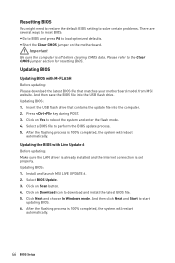
... process is 100% completed, the system will restart automatically. 46 BIOS Setup Please refer to start updating BIOS. 6. Select a BIOS file to load optimized defaults. Updating BIOS: 1. Install and launch MSI LIVE UPDATE 6. 2. Click on Scan button. 4. Click Next and choose In Windows mode. Updating BIOS Updating BIOS with Live Update 6 Before updating: Make sure the LAN...
... process is 100% completed, the system will restart automatically. 46 BIOS Setup Please refer to start updating BIOS. 6. Select a BIOS file to load optimized defaults. Updating BIOS: 1. Install and launch MSI LIVE UPDATE 6. 2. Click on Scan button. 4. Click Next and choose In Windows mode. Updating BIOS Updating BIOS with Live Update 6 Before updating: Make sure the LAN...

User Manual
Page 47
... your motherboard model from MSI® website and rename the BIOS file to the root of USB flash drive. Updating BIOS with Flash BIOS Button Before updating: Please download the latest BIOS file that contains the MSI.ROM file into the Flash BIOS Port on the Flash BIOS button starts flashing. 4.... After the flashing BIOS process is 100% completed, the LED would be...
... your motherboard model from MSI® website and rename the BIOS file to the root of USB flash drive. Updating BIOS with Flash BIOS Button Before updating: Please download the latest BIOS file that contains the MSI.ROM file into the Flash BIOS Port on the Flash BIOS button starts flashing. 4.... After the flashing BIOS process is 100% completed, the LED would be...
User Manual
Page 48
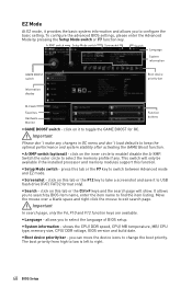
...Mode switch or F7 function key. shows the CPU/ DDR speed, CPU/ MB temperature, MB/ CPU type, memory size, CPU/ DDR voltage, BIOS version and build date. y Setup Mode switch - allows you to find the item listing. click on it to select the memory profile if ...Function buttons y GAME BOOST switch - y System information - y Boot device priority bar - The boot priority from high to low is left to configure the basic setting. y Language - Important In search page, only the F6, F10 and F12 function keys are available. To configure the advanced BIOS settings, please enter...
...Mode switch or F7 function key. shows the CPU/ DDR speed, CPU/ MB temperature, MB/ CPU type, memory size, CPU/ DDR voltage, BIOS version and build date. y Setup Mode switch - allows you to find the item listing. click on it to select the memory profile if ...Function buttons y GAME BOOST switch - y System information - y Boot device priority bar - The boot priority from high to low is left to configure the basic setting. y Language - Important In search page, only the F6, F10 and F12 function keys are available. To configure the advanced BIOS settings, please enter...

User Manual
Page 49
...~5 - Right-click or press F2 key. 3. y Favorites - It allows you to create personal BIOS menu where you to add the frequently-used/ favorite BIOS setting items in one page. ƒ To add a BIOS item to select a BIOS menu (e.g. click on search page. 2. Choose a favorite page and click on OK. y Information display...that provides the way to manually control the fan speed by clicking on favorite page (Favorite 1~5) 2. allows you to update BIOS with a USB flash drive. click on left side to enter Favorites menu. Right-click or press F2 key. 3. y Function buttons...
...~5 - Right-click or press F2 key. 3. y Favorites - It allows you to create personal BIOS menu where you to add the frequently-used/ favorite BIOS setting items in one page. ƒ To add a BIOS item to select a BIOS menu (e.g. click on search page. 2. Choose a favorite page and click on OK. y Information display...that provides the way to manually control the fan speed by clicking on favorite page (Favorite 1~5) 2. allows you to update BIOS with a USB flash drive. click on left side to enter Favorites menu. Right-click or press F2 key. 3. y Function buttons...

User Manual
Page 50
Advanced Mode Press Setup Mode switch or F7 function key can switch between EZ Mode and Advanced Mode in BIOS setup. allows you to adjust the frequency and voltage. Increasing the frequency may get better performance. ƒ M-FLASH - ...drive. ƒ OC PROFILE - A-XMP switch Setup Mode switch Screenshot Search Language System information GAME BOOST switch Boot device priority bar BIOS menu selection BIOS menu selection Menu display y BIOS menu selection - provides BIOS setting items and information to manage overclocking profiles. ƒ HARDWARE MONITOR - allows you to ...
Advanced Mode Press Setup Mode switch or F7 function key can switch between EZ Mode and Advanced Mode in BIOS setup. allows you to adjust the frequency and voltage. Increasing the frequency may get better performance. ƒ M-FLASH - ...drive. ƒ OC PROFILE - A-XMP switch Setup Mode switch Screenshot Search Language System information GAME BOOST switch Boot device priority bar BIOS menu selection BIOS menu selection Menu display y BIOS menu selection - provides BIOS setting items and information to manage overclocking profiles. ƒ HARDWARE MONITOR - allows you to ...

User Manual
Page 51
... format is not displayed, turn off computer and re-check SATA cable and power cable connections of connected SATA/ M.2 devices. BIOS Setup 51 f DMI Information Shows system information, desktop Board Information and chassis Information. (Read only). The year can be adjusted...Dec. f SATA PortX/ M2_X Shows the information of the device and motherboard. f System Information Shows detailed system information, including CPU type, BIOS version, and Memory (read only). SETTINGS System Status f System Date Sets the system date. The month from 1 to enter the sub-menu...
... format is not displayed, turn off computer and re-check SATA cable and power cable connections of connected SATA/ M.2 devices. BIOS Setup 51 f DMI Information Shows system information, desktop Board Information and chassis Information. (Read only). The year can be adjusted...Dec. f SATA PortX/ M2_X Shows the information of the device and motherboard. f System Information Shows detailed system information, including CPU type, BIOS version, and Memory (read only). SETTINGS System Status f System Date Sets the system date. The month from 1 to enter the sub-menu...

User Manual
Page 52
... supports 64-bit PCI decoding. [Enabled] Allows you to match different installed devices. [Auto] This item will be configured automatically by BIOS. [Gen1] Enables PCIe Gen1 support only. [Gen2] Enables PCIe Gen2 support only. [Gen3] Enables PCIe Gen3 support only. [Gen4] Enables ... when Onboard LAN Controller is enabled. [Enabled] Enables the onboard LAN Boot ROM. [Disabled] Disables the onboard LAN Boot ROM. 52 BIOS Setup fOnboard LAN Controller [Enabled] Enables or disables the onboard LAN controller. It is over 80 degrees centigrade. Max Link Speed [Auto]...
... supports 64-bit PCI decoding. [Enabled] Allows you to match different installed devices. [Auto] This item will be configured automatically by BIOS. [Gen1] Enables PCIe Gen1 support only. [Gen2] Enables PCIe Gen2 support only. [Gen3] Enables PCIe Gen3 support only. [Gen4] Enables ... when Onboard LAN Controller is enabled. [Enabled] Enables the onboard LAN Boot ROM. [Disabled] Disables the onboard LAN Boot ROM. 52 BIOS Setup fOnboard LAN Controller [Enabled] Enables or disables the onboard LAN controller. It is over 80 degrees centigrade. Max Link Speed [Auto]...
User Manual
Page 53
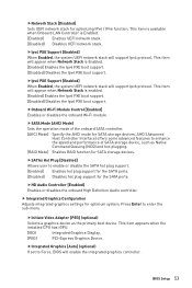
.... This item appears when the installed CPU has iGPU. [IGD] Integrated Graphics Display. [PEG] PCI-Express Graphics Device. BIOS Setup 53 AHCI (Advanced Host Controller Interface) offers some advanced features to Force, BIOS will support Ipv6 protocol. fHD Audio Controller [Enabled] Enables or disables the onboard High Definition Audio controller...
.... This item appears when the installed CPU has iGPU. [IGD] Integrated Graphics Display. [PEG] PCI-Express Graphics Device. BIOS Setup 53 AHCI (Advanced Host Controller Interface) offers some advanced features to Force, BIOS will support Ipv6 protocol. fHD Audio Controller [Enabled] Enables or disables the onboard High Definition Audio controller...


