User Manual
Page 13
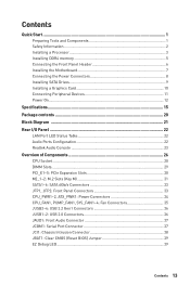
... Connectors 36 JUSB1~2: USB 2.0 Connectors 36 JAUD1: Front Audio Connector 37 JCOM1: Serial Port Connector 37 JCI1: Chassis Intrusion Connector 38 JBAT1: Clear CMOS (Reset BIOS) Jumper 39 EZ Debug LED...39 Contents 13
... Connectors 36 JUSB1~2: USB 2.0 Connectors 36 JAUD1: Front Audio Connector 37 JCOM1: Serial Port Connector 37 JCI1: Chassis Intrusion Connector 38 JBAT1: Clear CMOS (Reset BIOS) Jumper 39 EZ Debug LED...39 Contents 13
User Manual
Page 14
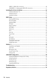
...~2: Addressable RGB LED connectors 41 Installing OS, Drivers & Utilities 42 Installing Windows® 10 42 Installing Drivers 42 Installing Utilities 42 BIOS Setup ...43 Entering BIOS Setup 43 Resetting BIOS...44 Updating BIOS...44 EZ Mode ...46 Advanced Mode ...48 SETTINGS...49 Advanced...49 Boot...54 Security ...55 Save & Exit...56 OC...57 M-FLASH...
...~2: Addressable RGB LED connectors 41 Installing OS, Drivers & Utilities 42 Installing Windows® 10 42 Installing Drivers 42 Installing Utilities 42 BIOS Setup ...43 Entering BIOS Setup 43 Resetting BIOS...44 Updating BIOS...44 EZ Mode ...46 Advanced Mode ...48 SETTINGS...49 Advanced...49 Boot...54 Security ...55 Save & Exit...56 OC...57 M-FLASH...

User Manual
Page 18
x 9.6 in . Continued from previous page Back Panel Connectors I/O Controller Hardware Monitor Form Factor BIOS Features Software y 1x Flash BIOS Button y 1x PS/2 keyboard/ mouse combo port y 2x USB 2.0 ports y 2x WiFi/ Bluetooth antenna jacks y 2x USB 3.2 Gen 1 ports y 1x HDMI port y 1x USB 3.2 Gen 2/ 1 Type ... y 12 in . (30.4 cm x 24.3 cm) y 1x 256 Mb flash y UEFI AMI BIOS y ACPI 6.1, SM BIOS 2.8 y Multi-language y Drivers y DRAGON CENTER y Nahimic Audio y CPU-Z MSI GAMING y MSI App Player (BlueStacks) y Google Chrome™ ,Google Toolbar, Google Drive y Norton™ Internet Security ...
x 9.6 in . Continued from previous page Back Panel Connectors I/O Controller Hardware Monitor Form Factor BIOS Features Software y 1x Flash BIOS Button y 1x PS/2 keyboard/ mouse combo port y 2x USB 2.0 ports y 2x WiFi/ Bluetooth antenna jacks y 2x USB 3.2 Gen 1 ports y 1x HDMI port y 1x USB 3.2 Gen 2/ 1 Type ... y 12 in . (30.4 cm x 24.3 cm) y 1x 256 Mb flash y UEFI AMI BIOS y ACPI 6.1, SM BIOS 2.8 y Multi-language y Drivers y DRAGON CENTER y Nahimic Audio y CPU-Z MSI GAMING y MSI App Player (BlueStacks) y Google Chrome™ ,Google Toolbar, Google Drive y Norton™ Internet Security ...
User Manual
Page 20
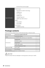
... ƒ USB with type A+C ƒ AMD Turbo USB 3.2 Gen 2 y BIOS ƒ Click BIOS 5 ƒ Flash BIOS y Certification ƒ GAMING Certified Package contents Please check the contents of the above items are damaged or missing, please contact your motherboard package. It should contain: Motherboard MPG X570 GAMING EDGE WIFI Cable SATA 6Gb/s Cables 2 RAINBOW RGB LED Extension Cable 80cm 1 Antenna...
... ƒ USB with type A+C ƒ AMD Turbo USB 3.2 Gen 2 y BIOS ƒ Click BIOS 5 ƒ Flash BIOS y Certification ƒ GAMING Certified Package contents Please check the contents of the above items are damaged or missing, please contact your motherboard package. It should contain: Motherboard MPG X570 GAMING EDGE WIFI Cable SATA 6Gb/s Cables 2 RAINBOW RGB LED Extension Cable 80cm 1 Antenna...

User Manual
Page 22
... Out Mic In (●: connected, Blank: empty) 22 Rear I /O Panel Wi-Fi Antenna connectors USB 3.2 PS/2 Gen1 Type-A LAN USB 3.2 Gen 2 Type-A* Flash BIOS Button Audio Ports Flash BIOS Port USB 2.0 Type-A USB 3.2 Gen 2 Type-A USB 3.2 Gen 2 Type-C* Optical S/PDIF-Out *USB 3.2 Gen2 (3rd Gen AMD Ryzen™) or USB 3.2 Gen1 (2nd... Gen AMD Ryzen™/Ryzen™ with Radeon™ Vega Graphics and 2nd Gen AMD Ryzen™ with Flash BIOS Button. Rear I /O Panel Please refer to page 45 for Updating...
... Out Mic In (●: connected, Blank: empty) 22 Rear I /O Panel Wi-Fi Antenna connectors USB 3.2 PS/2 Gen1 Type-A LAN USB 3.2 Gen 2 Type-A* Flash BIOS Button Audio Ports Flash BIOS Port USB 2.0 Type-A USB 3.2 Gen 2 Type-A USB 3.2 Gen 2 Type-C* Optical S/PDIF-Out *USB 3.2 Gen2 (3rd Gen AMD Ryzen™) or USB 3.2 Gen1 (2nd... Gen AMD Ryzen™/Ryzen™ with Radeon™ Vega Graphics and 2nd Gen AMD Ryzen™ with Flash BIOS Button. Rear I /O Panel Please refer to page 45 for Updating...
User Manual
Page 27
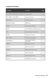
... Power Connectors 34 CPU Socket AM4 CPU Socket 28 DIMMA1/A2/B1/B2 DIMM Slots 29 JAUD1 Front Audio Connector 37 JBAT1 Clear CMOS (Reset BIOS) Jumper 39 JCI1 Chassis Intrusion Connector 38 JCOM1 Serial Port Connector 37 JFP1, JFP2 JRAINBOW1~2 JRGB1~2 Front Panel Connectors 33 Addressable RGB LED connectors 41...
... Power Connectors 34 CPU Socket AM4 CPU Socket 28 DIMMA1/A2/B1/B2 DIMM Slots 29 JAUD1 Front Audio Connector 37 JBAT1 Clear CMOS (Reset BIOS) Jumper 39 JCI1 Chassis Intrusion Connector 38 JCOM1 Serial Port Connector 37 JFP1, JFP2 JRAINBOW1~2 JRGB1~2 Front Panel Connectors 33 Addressable RGB LED connectors 41...
User Manual
Page 28
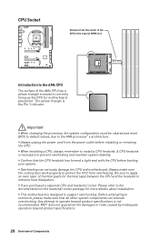
Important y When changing the processor, the system configuration could be cleared and reset BIOS to default values, due to install a CPU heatsink. y Confirm that all other system components can seriously damage the CPU and motherboard. Always make sure ...that the CPU heatsink has formed a tight seal with the CPU before installing or removing the CPU. A CPU heatsink is the Pin 1 indicator. MSI® does not guarantee the damages or risks caused by inadequate operation beyond product specifications is designed to support overclocking. The yellow triangle is necessary...
Important y When changing the processor, the system configuration could be cleared and reset BIOS to default values, due to install a CPU heatsink. y Confirm that all other system components can seriously damage the CPU and motherboard. Always make sure ...that the CPU heatsink has formed a tight seal with the CPU before installing or removing the CPU. A CPU heatsink is the Pin 1 indicator. MSI® does not guarantee the damages or risks caused by inadequate operation beyond product specifications is designed to support overclocking. The yellow triangle is necessary...

User Manual
Page 29
y Based on its Serial Presence Detect (SPD). Go to BIOS and find the DRAM Frequency to set the memory frequency if you want to use a more than the amount of memory will be a little less ...
y Based on its Serial Presence Detect (SPD). Go to BIOS and find the DRAM Frequency to set the memory frequency if you want to use a more than the amount of memory will be a little less ...

User Manual
Page 35
... 4 Speed Control Signal DC Mode pin definition 1 Ground 2 Voltage Control 3 Sense 4 NC Overview of the fan speed that allow you to adjust fan speed in BIOS > HARDWARE MONITOR. PWM Mode fan connectors provide constant 12V output and adjust fan speed with speed control signal.
... 4 Speed Control Signal DC Mode pin definition 1 Ground 2 Voltage Control 3 Sense 4 NC Overview of the fan speed that allow you to adjust fan speed in BIOS > HARDWARE MONITOR. PWM Mode fan connectors provide constant 12V output and adjust fan speed with speed control signal.

User Manual
Page 38
Connect the JCI1 connector to BIOS > SETTINGS > Security > Chassis Intrusion Configuration. 2. Close the chassis cover. 3. Resetting the chassis intrusion warning 1. Press F10 to save and exit and then press the Enter ...key to select Yes. 38 Overview of Components Go to the chassis intrusion switch/ sensor on . Go to Enabled. 5. Set Chassis Intrusion to BIOS > SETTINGS > Security > Chassis Intrusion Configuration. 4. Once the chassis cover is opened again, a warning message will be displayed on screen when the computer is turned on...
Connect the JCI1 connector to BIOS > SETTINGS > Security > Chassis Intrusion Configuration. 2. Close the chassis cover. 3. Resetting the chassis intrusion warning 1. Press F10 to save and exit and then press the Enter ...key to select Yes. 38 Overview of Components Go to the chassis intrusion switch/ sensor on . Go to Enabled. 5. Set Chassis Intrusion to BIOS > SETTINGS > Security > Chassis Intrusion Configuration. 4. Once the chassis cover is opened again, a warning message will be displayed on screen when the computer is turned on...
User Manual
Page 39
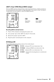
... JBAT1. 4. DRAM - indicates GPU is not detected or fail. indicates the booting device is not detected or fail. Keep Data (default) Clear CMOS/ Reset BIOS Resetting BIOS to short JBAT1 for about 5-10 seconds. 3. Plug the power cord and power on the motherboard to clear the CMOS memory. EZ Debug LED These...
... JBAT1. 4. DRAM - indicates GPU is not detected or fail. indicates the booting device is not detected or fail. Keep Data (default) Clear CMOS/ Reset BIOS Resetting BIOS to short JBAT1 for about 5-10 seconds. 3. Plug the power cord and power on the motherboard to clear the CMOS memory. EZ Debug LED These...

User Manual
Page 43
... should always keep the default settings to avoid possible system damage or failure booting unless you are continuously update for BIOS item description. Entering BIOS Setup Press Delete key, when the Press DEL key to enter Setup Menu, F11 to the HELP information panel for better ...the boot process. y The pictures in this chapter are for system stability in normal conditions. Ctrl+F: Enter Search page * When you purchased. BIOS Setup The default settings offer the optimal performance for reference only and may be for reference only. Function key F1: General Help list F2: ...
... should always keep the default settings to avoid possible system damage or failure booting unless you are continuously update for BIOS item description. Entering BIOS Setup Press Delete key, when the Press DEL key to enter Setup Menu, F11 to the HELP information panel for better ...the boot process. y The pictures in this chapter are for system stability in normal conditions. Ctrl+F: Enter Search page * When you purchased. BIOS Setup The default settings offer the optimal performance for reference only and may be for reference only. Function key F1: General Help list F2: ...
User Manual
Page 44
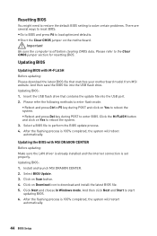
...; Reboot and press Del key during POST to the Clear CMOS jumper section for resetting BIOS. Click on Yes to download and install the latest BIOS file. 5. Click Next and choose In Windows mode. Updating BIOS: 1. Install and launch MSI DRAGON CENTER. 2. After the flashing process is 100% completed, the system will restart automatically...
...; Reboot and press Del key during POST to the Clear CMOS jumper section for resetting BIOS. Click on Yes to download and install the latest BIOS file. 5. Click Next and choose In Windows mode. Updating BIOS: 1. Install and launch MSI DRAGON CENTER. 2. After the flashing process is 100% completed, the system will restart automatically...
User Manual
Page 45
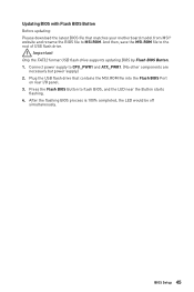
...off simultaneously. Updating BIOS with Flash BIOS Button Before updating: Please download the latest BIOS file that contains the MSI.ROM file into the Flash BIOS Port on rear I/O panel. 3. Connect power supply to MSI.ROM. Press the Flash BIOS Button to the root of USB flash drive. BIOS Setup 45 And then..., save the MSI.ROM file to flash BIOS, and the LED...
...off simultaneously. Updating BIOS with Flash BIOS Button Before updating: Please download the latest BIOS file that contains the MSI.ROM file into the Flash BIOS Port on rear I/O panel. 3. Connect power supply to MSI.ROM. Press the Flash BIOS Button to the root of USB flash drive. BIOS Setup 45 And then..., save the MSI.ROM file to flash BIOS, and the LED...
User Manual
Page 46
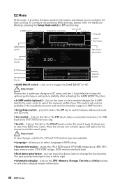
... Switch the outer circle to keep the optimal performance and system stability after activating the GAME BOOST function. Move the mouse over a blank space and right click the mouse to select language of BIOS setup. allows you to exit the search page. click on the CPU, Memory,...this tab or the Ctrl+F keys to display related information. 46 BIOS Setup y Information display - To configure the advanced BIOS settings, please enter the Advanced Mode by BIOS item name. y A-XMP switch (optional) - It allows you to toggle the GAME BOOST for OC. y Boot device priority bar - The boot ...
... Switch the outer circle to keep the optimal performance and system stability after activating the GAME BOOST function. Move the mouse over a blank space and right click the mouse to select language of BIOS setup. allows you to exit the search page. click on the CPU, Memory,...this tab or the Ctrl+F keys to display related information. 46 BIOS Setup y Information display - To configure the advanced BIOS settings, please enter the Advanced Mode by BIOS item name. y A-XMP switch (optional) - It allows you to toggle the GAME BOOST for OC. y Boot device priority bar - The boot ...

User Manual
Page 47
... but also on OK. y Favorites - allows you can save and access favorite/ frequently-used / favorite BIOS setting items in one page. ƒ To add a BIOS item to add the frequently-used BIOS setting items. ƒ Default HomePage - y Hardware Monitor - allows you to manually control the fan speed ...by clicking on this button to display the Hardware Monitor menu that provides the way to enter Favorites menu. SETTINGS, OC...,etc) as the BIOS home page. ƒ Favorite1~5 - Choose a favorite page and click on favorite page (Favorite 1~5) 2. Right-click or press F2 key. 3. Right...
... but also on OK. y Favorites - allows you can save and access favorite/ frequently-used / favorite BIOS setting items in one page. ƒ To add a BIOS item to add the frequently-used BIOS setting items. ƒ Default HomePage - y Hardware Monitor - allows you to manually control the fan speed ...by clicking on this button to display the Hardware Monitor menu that provides the way to enter Favorites menu. SETTINGS, OC...,etc) as the BIOS home page. ƒ Favorite1~5 - Choose a favorite page and click on favorite page (Favorite 1~5) 2. Right-click or press F2 key. 3. Right...

User Manual
Page 48
...Language System information GAME BOOST switch Boot device priority bar BIOS menu selection BIOS menu selection Menu display y BIOS menu selection - allows you to be configured. 48 BIOS Setup provides the way to specify the parameters for chipset and boot devices. ƒ OC - provides BIOS setting items and... information to manage overclocking profiles. ƒ HARDWARE MONITOR - allows you to update BIOS with a USB flash drive. ƒ OC PROFILE - allows you to set the ...
...Language System information GAME BOOST switch Boot device priority bar BIOS menu selection BIOS menu selection Menu display y BIOS menu selection - allows you to be configured. 48 BIOS Setup provides the way to specify the parameters for chipset and boot devices. ƒ OC - provides BIOS setting items and... information to manage overclocking profiles. ƒ HARDWARE MONITOR - allows you to update BIOS with a USB flash drive. ƒ OC PROFILE - allows you to set the ...
User Manual
Page 49
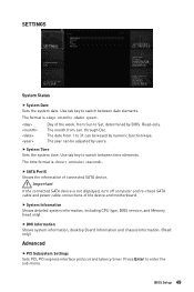
... Advanced f PCI Subsystem Settings Sets PCI, PCI express interface protocol and latency timer. Use tab key to Sat, determined by BIOS. Day of connected SATA device. Read-only. The year can be adjusted by numeric function keys. through Dec. f System ...Information Shows detailed system information, including CPU type, BIOS version, and Memory (read only). The time format is . f DMI Information Shows system information, desktop Board Information and chassis Information....
... Advanced f PCI Subsystem Settings Sets PCI, PCI express interface protocol and latency timer. Use tab key to Sat, determined by BIOS. Day of connected SATA device. Read-only. The year can be adjusted by numeric function keys. through Dec. f System ...Information Shows detailed system information, including CPU type, BIOS version, and Memory (read only). The time format is . f DMI Information Shows system information, desktop Board Information and chassis Information....
User Manual
Page 50
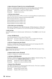
... when Onboard LAN Controller is over 55 and 75 degrees centigrade. fPCH Gen Switch [Auto] Sets PCI Express protocol of PCIe x16 slots for MSI M.2 Xpander / MSI M.2 Xpander-Z / Other M.2 PCIe storage card. f ACPI Settings Sets ACPI parameters of the onboard Power LED. [Dual Color] The power... vary with the installed processor. fAbove 4G memory/ Crypto Currency mining [Disabled] Enables or disables 64-bit capable devices to be configured automatically by BIOS. [Gen1] Enables PCIe Gen1 support only. [Gen2] Enables PCIe Gen2 support only. [Gen3] Enables PCIe Gen3 support only. [Gen4] Enables ...
... when Onboard LAN Controller is over 55 and 75 degrees centigrade. fPCH Gen Switch [Auto] Sets PCI Express protocol of PCIe x16 slots for MSI M.2 Xpander / MSI M.2 Xpander-Z / Other M.2 PCIe storage card. f ACPI Settings Sets ACPI parameters of the onboard Power LED. [Dual Color] The power... vary with the installed processor. fAbove 4G memory/ Crypto Currency mining [Disabled] Enables or disables 64-bit capable devices to be configured automatically by BIOS. [Gen1] Enables PCIe Gen1 support only. [Gen2] Enables PCIe Gen2 support only. [Gen3] Enables PCIe Gen3 support only. [Gen4] Enables ...

User Manual
Page 51
...f USB Configuration Sets the onboard USB controller and device function. This item will appear when Network Stack is enabled. BIOS Setup 51 fXHCI Hand-off [Enabled] Enables or disables XHCI hand-off feature. This item will be available when Integrated Graphics ...integrated graphics controller. f Integrated Graphics Configuration (optional) Adjusts integrated graphics settings for the SATA ports. Press Enter to Force, BIOS will appear when Network Stack is Enabled. [Enabled] Enables the Ipv4 PXE boot support. [Disabled] Disables the Ipv4 PXE boot support....
...f USB Configuration Sets the onboard USB controller and device function. This item will appear when Network Stack is enabled. BIOS Setup 51 fXHCI Hand-off [Enabled] Enables or disables XHCI hand-off feature. This item will be available when Integrated Graphics ...integrated graphics controller. f Integrated Graphics Configuration (optional) Adjusts integrated graphics settings for the SATA ports. Press Enter to Force, BIOS will appear when Network Stack is Enabled. [Enabled] Enables the Ipv4 PXE boot support. [Disabled] Disables the Ipv4 PXE boot support....


