User Manual
Page 1
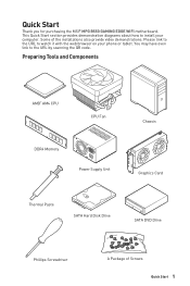
... provide video demonstrations. You may have even link to watch it with the web browser on your computer. Quick Start Thank you for purchasing the MSI® MPG B550 GAMING EDGE WIFI motherboard. Please link to the URL to the URL by scanning the QR code.
... provide video demonstrations. You may have even link to watch it with the web browser on your computer. Quick Start Thank you for purchasing the MSI® MPG B550 GAMING EDGE WIFI motherboard. Please link to the URL to the URL by scanning the QR code.

User Manual
Page 2
... prone to user guide. ▪▪The motherboard has been dropped and damaged. ▪▪The motherboard has obvious sign of breakage. ∙∙Do not leave this motherboard away from electrostatic discharge (ESD). Please adhere to the following situations arises, get the motherboard checked by the edges to avoid touching sensitive components. ∙∙...
... prone to user guide. ▪▪The motherboard has been dropped and damaged. ▪▪The motherboard has obvious sign of breakage. ∙∙Do not leave this motherboard away from electrostatic discharge (ESD). Please adhere to the following situations arises, get the motherboard checked by the edges to avoid touching sensitive components. ∙∙...

User Manual
Page 7
Installing the Motherboard https://youtu.be/wWI6Qt51Wnc 1 Torque: 3 kgf·cm* 3 *3 kgf·cm = 0.3 N·m = 2.6 lbf·in Quick Start 7
Installing the Motherboard https://youtu.be/wWI6Qt51Wnc 1 Torque: 3 kgf·cm* 3 *3 kgf·cm = 0.3 N·m = 2.6 lbf·in Quick Start 7

User Manual
Page 13
Contents Quick Start ...1 Preparing Tools and Components 1 Safety Information 2 Installing a Processor 3 Installing DDR4 memory 5 Connecting the Front Panel Header 6 Installing the Motherboard 7 Connecting the Power Connectors 8 Installing SATA Drives 9 Installing a Graphics Card 10 Connecting Peripheral Devices 11 Power On...12 Specifications...15 Package contents 21 Block Diagram ......
Contents Quick Start ...1 Preparing Tools and Components 1 Safety Information 2 Installing a Processor 3 Installing DDR4 memory 5 Connecting the Front Panel Header 6 Installing the Motherboard 7 Connecting the Power Connectors 8 Installing SATA Drives 9 Installing a Graphics Card 10 Connecting Peripheral Devices 11 Power On...12 Specifications...15 Package contents 21 Block Diagram ......
User Manual
Page 21
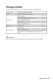
Package contents 21 Package contents Please check the contents of the above items are damaged or missing, please contact your motherboard package. It should contain: Motherboard Cable Accessories Application Documentation MPG B550 GAMING EDGE WIFI SATA 6G cables (2 cables/pack) 1 Wi-Fi antenna 1 80cm JRAINBOW cable (3pin-to-4pin) 1 M.2 screws (3 pcs./pack) 1 Case badge 1 Product registration card 1 Driver DVD 1 User manual 1 Quick installation guide 1 MSI components compatibility & reward program card 1 ⚠⚠Important If any of your retailer.
Package contents 21 Package contents Please check the contents of the above items are damaged or missing, please contact your motherboard package. It should contain: Motherboard Cable Accessories Application Documentation MPG B550 GAMING EDGE WIFI SATA 6G cables (2 cables/pack) 1 Wi-Fi antenna 1 80cm JRAINBOW cable (3pin-to-4pin) 1 M.2 screws (3 pcs./pack) 1 Case badge 1 Product registration card 1 Driver DVD 1 User manual 1 Quick installation guide 1 MSI components compatibility & reward program card 1 ⚠⚠Important If any of your retailer.

User Manual
Page 29
... to prevent overheating and maintain system stability. ∙∙Confirm that all other system components can seriously damage the CPU and motherboard. The yellow triangle is the Pin 1 indicator. ⚠⚠Important ∙∙When changing the processor, the system configuration...refer to the documentation in correctly lining up the CPU for more details about installation. ∙∙This motherboard is designed to support overclocking. MSI® does not guarantee the damages or risks caused by inadequate operation beyond product specifications is not recommended....
... to prevent overheating and maintain system stability. ∙∙Confirm that all other system components can seriously damage the CPU and motherboard. The yellow triangle is the Pin 1 indicator. ⚠⚠Important ∙∙When changing the processor, the system configuration...refer to the documentation in correctly lining up the CPU for more details about installation. ∙∙This motherboard is designed to support overclocking. MSI® does not guarantee the damages or risks caused by inadequate operation beyond product specifications is not recommended....

User Manual
Page 32
... SATA4 SATA3 ⚠⚠Important ∙∙Please do not fold the SATA cable at a 90-degree angle. M2_1 http://youtu.be connected to the motherboard for space saving purposes. M2_1~2: M.2 Slots (Key M) ⚽⚽Video Demonstration Watch the video to learn how to one SATA device. Loosen the screws of...
... SATA4 SATA3 ⚠⚠Important ∙∙Please do not fold the SATA cable at a 90-degree angle. M2_1 http://youtu.be connected to the motherboard for space saving purposes. M2_1~2: M.2 Slots (Key M) ⚽⚽Video Demonstration Watch the video to learn how to one SATA device. Loosen the screws of...

User Manual
Page 35
... Make sure that all the power cables are securely connected to a proper ATX power supply to ensure stable operation of Components 35 Overview of the motherboard.
... Make sure that all the power cables are securely connected to a proper ATX power supply to ensure stable operation of Components 35 Overview of the motherboard.

User Manual
Page 40
Use a jumper cap to clear the CMOS memory. Plug the power cord and Power on the motherboard to default values 1. If you want to clear the system configuration, set the jumpers to short JBAT1 for about 5-10 seconds. 3. Remove the jumper cap from a battery located on the computer. 40 Overview of Components JBAT1: Clear CMOS (Reset BIOS) Jumper There is CMOS memory onboard that is external powered from JBAT1. 4. Power off the computer and unplug the power cord. 2. Keep Data (default) Clear CMOS/ Reset BIOS Resetting BIOS to save system configuration data.
Use a jumper cap to clear the CMOS memory. Plug the power cord and Power on the motherboard to default values 1. If you want to clear the system configuration, set the jumpers to short JBAT1 for about 5-10 seconds. 3. Remove the jumper cap from a battery located on the computer. 40 Overview of Components JBAT1: Clear CMOS (Reset BIOS) Jumper There is CMOS memory onboard that is external powered from JBAT1. 4. Power off the computer and unplug the power cord. 2. Keep Data (default) Clear CMOS/ Reset BIOS Resetting BIOS to save system configuration data.

User Manual
Page 43
indicates DRAM is not detected or fail. LED_OFF LED_ON (Default) Overview of motherboard. DRAM - indicates GPU/ PCIE/ M.2 device is not detected or fail. LED_SW1: EZ LED Control This switch is used to switch on/ off all the LEDs of Components 43 CPU - indicates CPU is not detected or fail. VGA - indicates the booting device is not detected or fail. BOOT - EZ Debug LED These LEDs indicate the debug status of the motherboard.
indicates DRAM is not detected or fail. LED_OFF LED_ON (Default) Overview of motherboard. DRAM - indicates GPU/ PCIE/ M.2 device is not detected or fail. LED_SW1: EZ LED Control This switch is used to switch on/ off all the LEDs of Components 43 CPU - indicates CPU is not detected or fail. VGA - indicates the booting device is not detected or fail. BOOT - EZ Debug LED These LEDs indicate the debug status of the motherboard.

User Manual
Page 45
.... new devices may not provide backward compatibility. ∙∙Supports secure startup - the system will completely replace BIOS in this motherboard supports only Windows 10 64-bit operating system. ∙∙ Older graphics card - And also eliminates the time to switch ...Unified Extensible Firmware Interface) architecture. CPU Temperature: Motherboard Temperature: VCore: DDR Voltage: BIOS Mode: UEFI UEFI boot mode CPU Temperature: Motherboard Temperature: VCore: DDR Voltage: BIOS Mode: UEFI/Legacy CSM boot mode UEFI BIOS 45 The MSI UEFI BIOS uses UEFI as the default boot...
.... new devices may not provide backward compatibility. ∙∙Supports secure startup - the system will completely replace BIOS in this motherboard supports only Windows 10 64-bit operating system. ∙∙ Older graphics card - And also eliminates the time to switch ...Unified Extensible Firmware Interface) architecture. CPU Temperature: Motherboard Temperature: VCore: DDR Voltage: BIOS Mode: UEFI UEFI boot mode CPU Temperature: Motherboard Temperature: VCore: DDR Voltage: BIOS Mode: UEFI/Legacy CSM boot mode UEFI BIOS 45 The MSI UEFI BIOS uses UEFI as the default boot...
User Manual
Page 47
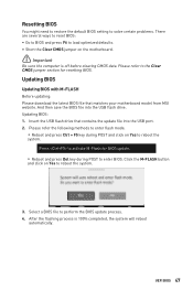
... Yes to enter BIOS. UEFI BIOS 47 Select a BIOS file to load optimized defaults. ∙∙Short the Clear CMOS jumper on the motherboard. ⚠⚠Important Be sure the computer is 100% completed, the system will reboot automatically. Please refer the following methods to enter flash ... during POST and click on Yes to the Clear CMOS jumper section for resetting BIOS. Insert the USB flash drive that matches your motherboard model from MSI website. After the flashing process is off before clearing CMOS data. And then save the BIOS file into the USB port. 2. Updating...
... Yes to enter BIOS. UEFI BIOS 47 Select a BIOS file to load optimized defaults. ∙∙Short the Clear CMOS jumper on the motherboard. ⚠⚠Important Be sure the computer is 100% completed, the system will reboot automatically. Please refer the following methods to enter flash ... during POST and click on Yes to the Clear CMOS jumper section for resetting BIOS. Insert the USB flash drive that matches your motherboard model from MSI website. After the flashing process is off before clearing CMOS data. And then save the BIOS file into the USB port. 2. Updating...
User Manual
Page 48
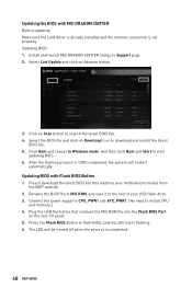
Select the BIOS file and click on Scan button to the root of your motherboard model from the MSI® website. 2. After the flashing process is completed. 48 UEFI BIOS Connect the power supply to CPU_PWR1 and ATX_PWR1. (No need to download and install .... 5. Plug the USB flash drive that matches your USB flash drive. 3. Click on Download icon to install CPU and memory.) 4. Rename the BIOS file to MSI.ROM, and save it to search the latest BIOS file. 4. Select Live Update and click on the rear I/O panel. 5. The LED will be turned off...
Select the BIOS file and click on Scan button to the root of your motherboard model from the MSI® website. 2. After the flashing process is completed. 48 UEFI BIOS Connect the power supply to CPU_PWR1 and ATX_PWR1. (No need to download and install .... 5. Plug the USB flash drive that matches your USB flash drive. 3. Click on Download icon to install CPU and memory.) 4. Rename the BIOS file to MSI.ROM, and save it to search the latest BIOS file. 4. Select Live Update and click on the rear I/O panel. 5. The LED will be turned off...
User Manual
Page 49
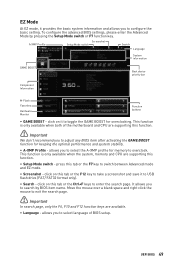
...is only available when both of BIOS setup. click on this tab or the F12 key to take a screenshot and save it to toggle the GAME BOOST for overclocking. Move the mouse over a blank space and right click the mouse to configure the basic setting. This function is only available when...9888;Important We don't recommend you to adjust any BIOS item after activating the GAME BOOST function for memory to switch between Advanced mode and EZ mode. ∙∙ Screenshot - allows you to select language of the motherboard and CPU are supporting this tab or the F7 key to overclock. EZ Mode...
...is only available when both of BIOS setup. click on this tab or the F12 key to take a screenshot and save it to toggle the GAME BOOST for overclocking. Move the mouse over a blank space and right click the mouse to configure the basic setting. This function is only available when...9888;Important We don't recommend you to adjust any BIOS item after activating the GAME BOOST function for memory to switch between Advanced mode and EZ mode. ∙∙ Screenshot - allows you to select language of the motherboard and CPU are supporting this tab or the F7 key to overclock. EZ Mode...

User Manual
Page 50
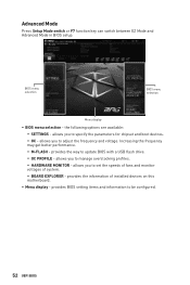
... size, CPU/ DDR voltage, BIOS version and build date. ∙∙ Boot device priority bar - The boot priority from high to update BIOS with the motherboard you to manually control the fan speed by clicking on this button to enter the Hardware Monitor menu that provides the way to low is...
... size, CPU/ DDR voltage, BIOS version and build date. ∙∙ Boot device priority bar - The boot priority from high to update BIOS with the motherboard you to manually control the fan speed by clicking on this button to enter the Hardware Monitor menu that provides the way to low is...
User Manual
Page 52
... between EZ Mode and Advanced Mode in BIOS setup. allows you to set the speeds of fans and monitor voltages of installed devices on this motherboard. ∙∙ Menu display -
... between EZ Mode and Advanced Mode in BIOS setup. allows you to set the speeds of fans and monitor voltages of installed devices on this motherboard. ∙∙ Menu display -

User Manual
Page 53
..., SSD, USB and audio. The format is not displayed, turn off computer and re-check SATA/ M.2 cable and power cable connections of the device and motherboard. ▶▶System Information Shows detailed system information, including CPU type, BIOS version, and Memory (read only). ▶▶DMI Information Shows system information, desktop...
..., SSD, USB and audio. The format is not displayed, turn off computer and re-check SATA/ M.2 cable and power cable connections of the device and motherboard. ▶▶System Information Shows detailed system information, including CPU type, BIOS version, and Memory (read only). ▶▶DMI Information Shows system information, desktop...
User Manual
Page 55
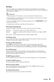
This item can set the parameters about CPU power/ current. User can only be available when the installed processor, memory modules and motherboard support this function. ▶▶Advanced CPU Configuration Press Enter to determine CPU clock speed. Please note the overclocking behavior is not ...the normal or expert version of OC settings. [Normal] Provides the regular OC settings in BIOS setup. UEFI BIOS 55 Note: We use GAME BOOST function for easy overclocking. ∙∙The BIOS items in OC menu will be changed if the processor supports this function. ▶&#...
This item can set the parameters about CPU power/ current. User can only be available when the installed processor, memory modules and motherboard support this function. ▶▶Advanced CPU Configuration Press Enter to determine CPU clock speed. Please note the overclocking behavior is not ...the normal or expert version of OC settings. [Normal] Provides the regular OC settings in BIOS setup. UEFI BIOS 55 Note: We use GAME BOOST function for easy overclocking. ∙∙The BIOS items in OC menu will be changed if the processor supports this function. ▶&#...

User Manual
Page 57
... Please download the latest BIOS file that contains the update file into your USB flash drive. Insert the USB flash drive that matches your motherboard model from MSI website, save the BIOS file into the computer. 2. After the flashing process is 100% completed, the system will reboot automatically. And then follow the...
... Please download the latest BIOS file that contains the update file into your USB flash drive. Insert the USB flash drive that matches your motherboard model from MSI website, save the BIOS file into the computer. 2. After the flashing process is 100% completed, the system will reboot automatically. And then follow the...

User Manual
Page 60
Click and drag the duty points to be adjusted Duty points ⚠⚠Important The pictures in this section are for reference only and may vary from the motherboard you want to adjust and to display the fan duty curve line (yellow) in fan operating windows. 2. Select a fan to adjust the fan speed. Selects a fan that you purchased. 60 UEFI BIOS Adjusting fans 1.
Click and drag the duty points to be adjusted Duty points ⚠⚠Important The pictures in this section are for reference only and may vary from the motherboard you want to adjust and to display the fan duty curve line (yellow) in fan operating windows. 2. Select a fan to adjust the fan speed. Selects a fan that you purchased. 60 UEFI BIOS Adjusting fans 1.


