User Manual
Page 1
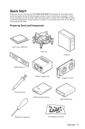
Some of Screws Quick Start 1 Preparing Tools and Components Intel® LGA 1200 CPU CPU Fan DDR4 Memory Power Supply Unit Chassis Graphics Card Thermal Paste SATA Hard Disk Drive SATA DVD Drive Phillips Screwdriver A Package of the installations also provide video demonstrations. You may ... web browser on your computer. Please link to the URL to the URL by scanning the QR code. Quick Start Thank you for purchasing the MSI® MEG Z490 UNIFY motherboard. This Quick Start section provides demonstration diagrams about how to install your phone or tablet.
Some of Screws Quick Start 1 Preparing Tools and Components Intel® LGA 1200 CPU CPU Fan DDR4 Memory Power Supply Unit Chassis Graphics Card Thermal Paste SATA Hard Disk Drive SATA DVD Drive Phillips Screwdriver A Package of the installations also provide video demonstrations. You may ... web browser on your computer. Please link to the URL to the URL by scanning the QR code. Quick Start Thank you for purchasing the MSI® MEG Z490 UNIFY motherboard. This Quick Start section provides demonstration diagrams about how to install your phone or tablet.
User Manual
Page 2
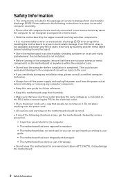
...this motherboard away from electrostatic discharge (ESD). Loose connections may damage the motherboard. 2 Safety Information Do not place anything over the power cord. ∙∙All cautions and warnings on the motherboard should be noted. ∙∙If any computer component. ∙...need help during any installation step, please consult a certified computer technician. ∙∙Always turn off the power supply and unplug the power cord from the power outlet before installing or removing any of static electricity by the edges to avoid touching sensitive components. ∙&#...
...this motherboard away from electrostatic discharge (ESD). Loose connections may damage the motherboard. 2 Safety Information Do not place anything over the power cord. ∙∙All cautions and warnings on the motherboard should be noted. ∙∙If any computer component. ∙...need help during any installation step, please consult a certified computer technician. ∙∙Always turn off the power supply and unplug the power cord from the power outlet before installing or removing any of static electricity by the edges to avoid touching sensitive components. ∙&#...
User Manual
Page 31
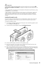
... for SLI configurations, please refer to the user guide of your graphics card to make sure you need to use a tool such as MSI Gaming Series Graphics Card Bolster to support its weight to prevent deformation of the slot. ∙∙For a single PCIe x16 expansion card...slot is recommended. ∙∙When adding or removing expansion cards, always turn off your graphics card package. 5. Turn off the power supply and unplug the power supply power cable from the menu, click on Configure SLI, Surround, PhysX in the left task pane and select Maximize 3D performance in your computer...
... for SLI configurations, please refer to the user guide of your graphics card to make sure you need to use a tool such as MSI Gaming Series Graphics Card Bolster to support its weight to prevent deformation of the slot. ∙∙For a single PCIe x16 expansion card...slot is recommended. ∙∙When adding or removing expansion cards, always turn off your graphics card package. 5. Turn off the power supply and unplug the power supply power cable from the menu, click on Configure SLI, Surround, PhysX in the left task pane and select Maximize 3D performance in your computer...
User Manual
Page 36
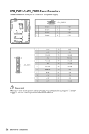
... These connectors allow you to connect an ATX power supply. 8 5 CPU_PWR1~2 4 1 1 Ground 5 2 Ground 6 3 Ground 7 4 Ground 8 +12V +12V +12V +12V 1 +3.3V 13 2 +3.3V 14 3 Ground 15 12 24 4 +5V 16 5 Ground 17 6 +5V 18 ATX_PWR1 7 Ground ... 23 12 +3.3V 24 +3.3V -12V Ground PS-ON# Ground Ground Ground Res +5V +5V +5V Ground ⚠⚠Important Make sure that all the power cables are securely connected to a proper ATX power supply to ensure stable operation of the motherboard. 36 Overview of Components
... These connectors allow you to connect an ATX power supply. 8 5 CPU_PWR1~2 4 1 1 Ground 5 2 Ground 6 3 Ground 7 4 Ground 8 +12V +12V +12V +12V 1 +3.3V 13 2 +3.3V 14 3 Ground 15 12 24 4 +5V 16 5 Ground 17 6 +5V 18 ATX_PWR1 7 Ground ... 23 12 +3.3V 24 +3.3V -12V Ground PS-ON# Ground Ground Ground Res +5V +5V +5V Ground ⚠⚠Important Make sure that all the power cables are securely connected to a proper ATX power supply to ensure stable operation of the motherboard. 36 Overview of Components

User Manual
Page 47
... connector supports up to control the extended LED strip. Overview of 3A (12V). ∙∙Always turn off the power supply and unplug the power cord from the power outlet before installing or removing the RGB LED strip. ∙∙Please use MSI's software to 2 meters continuous 5050 RGB LED strips (12V/G/R/B) with the maximum...
... connector supports up to control the extended LED strip. Overview of 3A (12V). ∙∙Always turn off the power supply and unplug the power cord from the power outlet before installing or removing the RGB LED strip. ∙∙Please use MSI's software to 2 meters continuous 5050 RGB LED strips (12V/G/R/B) with the maximum...
User Manual
Page 48
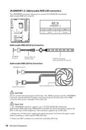
...The JRAINBOW connector supports up to 200 LEDs. ∙∙Always turn off the power supply and unplug the power cord from the power outlet before installing or removing the RGB LED strip. ∙∙Please use MSI's software to 75 LEDs WS2812B Individually Addressable RGB LED strips (5V/Data/Ground) ...with the maximum power rating of 3A (5V). In the case of 20% brightness, the connector supports up to control the ...
...The JRAINBOW connector supports up to 200 LEDs. ∙∙Always turn off the power supply and unplug the power cord from the power outlet before installing or removing the RGB LED strip. ∙∙Please use MSI's software to 75 LEDs WS2812B Individually Addressable RGB LED strips (5V/Data/Ground) ...with the maximum power rating of 3A (5V). In the case of 20% brightness, the connector supports up to control the ...
User Manual
Page 61
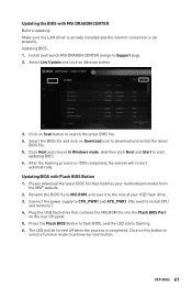
...and go to install CPU and memory.) 4. Please download the latest BIOS file that contains the MSI.ROM file into the Flash BIOS Port on Download icon to search the latest BIOS file. 4. Connect the power supply to CPU_PWR1 and ATX_PWR1. (No need to Support page. 2. The LED will restart automatically. ...Next and Start to achieve by reset button. Press the Flash BIOS Button to the root of your motherboard model from the MSI® website. 2. Rename the BIOS file to MSI.ROM, and save it to flash BIOS, and the LED starts flashing. 6. Updating the BIOS with Flash BIOS Button 1.
...and go to install CPU and memory.) 4. Please download the latest BIOS file that contains the MSI.ROM file into the Flash BIOS Port on Download icon to search the latest BIOS file. 4. Connect the power supply to CPU_PWR1 and ATX_PWR1. (No need to Support page. 2. The LED will restart automatically. ...Next and Start to achieve by reset button. Press the Flash BIOS Button to the root of your motherboard model from the MSI® website. 2. Rename the BIOS file to MSI.ROM, and save it to flash BIOS, and the LED starts flashing. 6. Updating the BIOS with Flash BIOS Button 1.
User Manual
Page 88
... headphones, HDMI cables, USB audio devices. ∙∙Test with another known working power supply of equal or greater wattage. There is turned on the motherboard rear IO panel. The power is set to an electrical outlet securely. ∙∙Check if all customized settings ... known working speaker or headphone. Troubleshooting Before sending the motherboard for RMA repair, try to the motherboard? ∙∙Some power supply units have a power button on the rear side, make sure the LAN port LEDs are properly illuminated. ∙∙Verify your TCP/IP settings...
... headphones, HDMI cables, USB audio devices. ∙∙Test with another known working power supply of equal or greater wattage. There is turned on the motherboard rear IO panel. The power is set to an electrical outlet securely. ∙∙Check if all customized settings ... known working speaker or headphone. Troubleshooting Before sending the motherboard for RMA repair, try to the motherboard? ∙∙Some power supply units have a power button on the rear side, make sure the LAN port LEDs are properly illuminated. ∙∙Verify your TCP/IP settings...

