
User Manual
Page 15
...9642;2DPC 2R Max speed up to 4000+ MHz ∙∙Supports Dual-Channel mode ∙∙Supports non-ECC, un-buffered memory ∙∙Supports Intel® Extreme Memory Profile (XMP) *Please refer www.msi.com for compatibility information. * Onboard graphics output are disabled when ... for LGA 1200 socket* * Please go to the latest version from PCH) ∙∙Supports 2-Way NVIDIA® SLI™ Technology ∙∙Supports 3-Way AMD® CrossFire™ Technology Intel® Z490 Chipset ∙∙6x SATA 6Gb/s ports* ∙∙3x M.2 slots (Key M) ...
...9642;2DPC 2R Max speed up to 4000+ MHz ∙∙Supports Dual-Channel mode ∙∙Supports non-ECC, un-buffered memory ∙∙Supports Intel® Extreme Memory Profile (XMP) *Please refer www.msi.com for compatibility information. * Onboard graphics output are disabled when ... for LGA 1200 socket* * Please go to the latest version from PCH) ∙∙Supports 2-Way NVIDIA® SLI™ Technology ∙∙Supports 3-Way AMD® CrossFire™ Technology Intel® Z490 Chipset ∙∙6x SATA 6Gb/s ports* ∙∙3x M.2 slots (Key M) ...

User Manual
Page 16
...port on the back panel Realtek® ALC1220 Codec + ESS E9018Q2C combo DAC Audio ∙∙7.1-Channel High Definition Audio ∙∙Supports S/PDIF output ∙∙1x Clear CMOS ∙∙1x Flash BIOS button ∙∙1x PS/2 keyboard/ mouse combo port &#...;5x OFC audio jacks Continued on next page 16 Specifications Continued from previous page Intel® Z490 Chipset RAID ∙∙Supports RAID 0, RAID1, RAID 5 and RAID 10 for SATA storage devices ∙∙Supports RAID 0, RAID 1 and RAID 5 for M.2 PCIe storage devices ∙∙1x Realtek...
...port on the back panel Realtek® ALC1220 Codec + ESS E9018Q2C combo DAC Audio ∙∙7.1-Channel High Definition Audio ∙∙Supports S/PDIF output ∙∙1x Clear CMOS ∙∙1x Flash BIOS button ∙∙1x PS/2 keyboard/ mouse combo port &#...;5x OFC audio jacks Continued on next page 16 Specifications Continued from previous page Intel® Z490 Chipset RAID ∙∙Supports RAID 0, RAID1, RAID 5 and RAID 10 for SATA storage devices ∙∙Supports RAID 0, RAID 1 and RAID 5 for M.2 PCIe storage devices ∙∙1x Realtek...

User Manual
Page 17
... ∙∙3x M.2 slots (M-Key) ∙∙1x USB 3.2 Gen 2 10Gbps Type-C port ∙∙1x USB 3.2 Gen 1 5Gbps connector (supports additional 2 USB 3.2 Gen 1 5Gbps ports) ∙∙2x USB 2.0 connectors (supports additional 4 USB 2.0 ports) ∙∙1x 4-pin CPU fan connector ∙∙1x 4-pin water-pump connector ∙∙6x...
... ∙∙3x M.2 slots (M-Key) ∙∙1x USB 3.2 Gen 2 10Gbps Type-C port ∙∙1x USB 3.2 Gen 1 5Gbps connector (supports additional 2 USB 3.2 Gen 1 5Gbps ports) ∙∙2x USB 2.0 connectors (supports additional 4 USB 2.0 ports) ∙∙1x 4-pin CPU fan connector ∙∙1x 4-pin water-pump connector ∙∙6x...
User Manual
Page 20
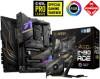
...: Motherboard MEG Z490 ACE User manual 1 Documentation Case stand-off notification 1 Quick installation guide 1 Application Driver DVD 1 Cables SATA 6G cables (2 cables/pack) 2 Wi-Fi Antenna 1 Case badge 1 Accessories SATA cable stickers 1 Product registration card 1 M.2 screws (3 pcs./pack) 1 ⚠⚠Important If any of your retailer. 20 Package contents JCORSAIR1 Connector Specification Supporting CORSAIR...
...: Motherboard MEG Z490 ACE User manual 1 Documentation Case stand-off notification 1 Quick installation guide 1 Application Driver DVD 1 Cables SATA 6G cables (2 cables/pack) 2 Wi-Fi Antenna 1 Case badge 1 Accessories SATA cable stickers 1 Product registration card 1 M.2 screws (3 pcs./pack) 1 ⚠⚠Important If any of your retailer. 20 Package contents JCORSAIR1 Connector Specification Supporting CORSAIR...
User Manual
Page 28
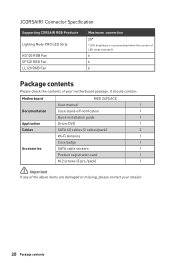
...to install a CPU heatsink. Before attempting to overclock, please make sure the cooling fans work properly to protect the CPU from overheating. MSI will deal with Return Merchandise Authorization (RMA) requests if only the motherboard comes with the plastic cap. ∙∙If you purchased...;Whenever the CPU is not installed, always protect the CPU socket pins by inadequate operation beyond product specifications is designed to support overclocking. Any attempt to operate beyond product specifications. 28 Overview of Components CPU Socket Distance from the center of the CPU...
...to install a CPU heatsink. Before attempting to overclock, please make sure the cooling fans work properly to protect the CPU from overheating. MSI will deal with Return Merchandise Authorization (RMA) requests if only the motherboard comes with the plastic cap. ∙∙If you purchased...;Whenever the CPU is not installed, always protect the CPU socket pins by inadequate operation beyond product specifications is designed to support overclocking. Any attempt to operate beyond product specifications. 28 Overview of Components CPU Socket Distance from the center of the CPU...

User Manual
Page 31
... SLI configurations, please refer to the user guide of your graphics card to make sure you need to use a tool such as MSI Gaming Series Graphics Card Bolster to support its weight to check for any necessary additional hardware or software changes. Connect the two cards together using the PCI_E1 slot is...
... SLI configurations, please refer to the user guide of your graphics card to make sure you need to use a tool such as MSI Gaming Series Graphics Card Bolster to support its weight to check for any necessary additional hardware or software changes. Connect the two cards together using the PCI_E1 slot is...

User Manual
Page 32
M2_1~3: M.2 Slots (Key M) ⚽⚽Video Demonstration Watch the video to learn how to Install M.2 module. Remove the M.2 SHIELD FROZR and remove the protective films from the thermal pads. 1 1 1 M2_1 1 M2_2 1 M2_3 1 2 2 2 32 Overview of M.2 SHIELD FROZR heatsink. 2. Loosen the screws of Components Installing M.2 module 1. M2_1 http://youtu.be/JCTFABytrYA M2_2 M2_3 ⚠⚠Important ∙∙Intel® RST only supports PCIe M.2 SSD with UEFI ROM. ∙∙Intel® Optane™ Memory Ready for all M.2 slots.
M2_1~3: M.2 Slots (Key M) ⚽⚽Video Demonstration Watch the video to learn how to Install M.2 module. Remove the M.2 SHIELD FROZR and remove the protective films from the thermal pads. 1 1 1 M2_1 1 M2_2 1 M2_3 1 2 2 2 32 Overview of M.2 SHIELD FROZR heatsink. 2. Loosen the screws of Components Installing M.2 module 1. M2_1 http://youtu.be/JCTFABytrYA M2_2 M2_3 ⚠⚠Important ∙∙Intel® RST only supports PCIe M.2 SSD with UEFI ROM. ∙∙Intel® Optane™ Memory Ready for all M.2 slots.

User Manual
Page 34
... a 90-degree angle. M.2 & SATA combination table Slot Available SATA connectors M2_1 PCIe SATA PCIe SATA PCIe M2_2 M2_3 PCIe PCIe SATA SATA ─ M2_3 slot supports PCIe only SATA1 SATA2 ✓ ✓ ✓ ✓ ✓ ✓ ─ ✓ ─ ✓ SATA3 ✓ ✓ ✓ ✓ ✓ SATA4 ✓ ✓ ✓ ✓...
... a 90-degree angle. M.2 & SATA combination table Slot Available SATA connectors M2_1 PCIe SATA PCIe SATA PCIe M2_2 M2_3 PCIe PCIe SATA SATA ─ M2_3 slot supports PCIe only SATA1 SATA2 ✓ ✓ ✓ ✓ ✓ ✓ ─ ✓ ─ ✓ SATA3 ✓ ✓ ✓ ✓ ✓ SATA4 ✓ ✓ ✓ ✓...

User Manual
Page 44
JTBT1: Thunderbolt Add-on Card Connector This connector allows you to connect the add-on Thunderbolt I/O card. 1 1 FORCE_PWR 2 3 SLP_S3# 4 5 GND SCI_EVENT SLP_S5# JRTD3: Intel RTD3 Connector This connector allows you to connect the RTD3 connector on the add-on Thunderbolt I/O card that supports RTD3. 1 1 WAKE 2 PWR EN 3 GND 44 Overview of Components
JTBT1: Thunderbolt Add-on Card Connector This connector allows you to connect the add-on Thunderbolt I/O card. 1 1 FORCE_PWR 2 3 SLP_S3# 4 5 GND SCI_EVENT SLP_S5# JRTD3: Intel RTD3 Connector This connector allows you to connect the RTD3 connector on the add-on Thunderbolt I/O card that supports RTD3. 1 1 WAKE 2 PWR EN 3 GND 44 Overview of Components

User Manual
Page 47
... off the power supply and unplug the power cord from the power outlet before installing or removing the RGB LED strip. ∙∙Please use MSI's software to control the extended LED strip. JRGB1: RGB LED connector The JRGB connector allows you to connect the 5050 RGB LED strips 12V. 1 1 +12V... LED Fan Connection JRGB connector 1 5050 RGB LED strips 12V GR B 1 System Fan connector RGB LED Fan ⚠⚠Important ∙∙The JRGB connector supports up to 2 meters continuous 5050 RGB LED strips (12V/G/R/B) with the maximum power rating of Components 47
... off the power supply and unplug the power cord from the power outlet before installing or removing the RGB LED strip. ∙∙Please use MSI's software to control the extended LED strip. JRGB1: RGB LED connector The JRGB connector allows you to connect the 5050 RGB LED strips 12V. 1 1 +12V... LED Fan Connection JRGB connector 1 5050 RGB LED strips 12V GR B 1 System Fan connector RGB LED Fan ⚠⚠Important ∙∙The JRGB connector supports up to 2 meters continuous 5050 RGB LED strips (12V/G/R/B) with the maximum power rating of Components 47

User Manual
Page 48
...5V LED strip to the JRGB connector will result in damage to the LED strip. ⚠⚠Important ∙∙The JRAINBOW connector supports up to 200 LEDs. ∙∙Always turn off the power supply and unplug the power cord from the power outlet before installing or... removing the RGB LED strip. ∙∙Please use MSI's software to connect the WS2812B Individually Addressable RGB LED strips 5V. 1 JRAINBOW1~2 1 +5V 2 Data 3 No Pin 4 Ground Addressable RGB LED Strip Connection 1 ...
...5V LED strip to the JRGB connector will result in damage to the LED strip. ⚠⚠Important ∙∙The JRAINBOW connector supports up to 200 LEDs. ∙∙Always turn off the power supply and unplug the power cord from the power outlet before installing or... removing the RGB LED strip. ∙∙Please use MSI's software to connect the WS2812B Individually Addressable RGB LED strips 5V. 1 JRAINBOW1~2 1 +5V 2 Data 3 No Pin 4 Ground Addressable RGB LED Strip Connection 1 ...

User Manual
Page 49
... function will not work. ∙∙Quantity of Components 49 Overview of RGB LED Fans or RGB LED Lighting PRO strips supported may differ between models. Please refer to connect the CORSAIR Individually Addressable Lighting PRO RGB LED strips 5V or CORSAIR RGB fans with... MSI's software. 1 JCORSAIR1 1 +5V 2 3 Ground Data CORSAIR RGB Fan Connection CORSAIR RGB LED fan SATA power SYS_FAN SYS_FAN CORSAIR fan hub 4 5 6 SYS_FAN 3 2 1...
... function will not work. ∙∙Quantity of Components 49 Overview of RGB LED Fans or RGB LED Lighting PRO strips supported may differ between models. Please refer to connect the CORSAIR Individually Addressable Lighting PRO RGB LED strips 5V or CORSAIR RGB fans with... MSI's software. 1 JCORSAIR1 1 +5V 2 3 Ground Data CORSAIR RGB Fan Connection CORSAIR RGB LED fan SATA power SYS_FAN SYS_FAN CORSAIR fan hub 4 5 6 SYS_FAN 3 2 1...

User Manual
Page 58
... top of the screen. When display a warning message There is compatible with a GUID Partition Table (GPT). ∙∙Supports unlimited number of partitions ∙∙Supports full capabilities of new devices - UEFI can directly boot the operating system and save the BIOS selftest process. UEFI BIOS... MSI UEFI BIOS is no GOP (Graphics Output protocol) support detected in this user guide refers to ensure that no malware tampers with a GOP/UEFI compatible graphics card ...
... top of the screen. When display a warning message There is compatible with a GUID Partition Table (GPT). ∙∙Supports unlimited number of partitions ∙∙Supports full capabilities of new devices - UEFI can directly boot the operating system and save the BIOS selftest process. UEFI BIOS... MSI UEFI BIOS is no GOP (Graphics Output protocol) support detected in this user guide refers to ensure that no malware tampers with a GOP/UEFI compatible graphics card ...

User Manual
Page 61
Select Live Update and click on this button to select a function mode to Support page. 2. Please download the latest BIOS file that contains the MSI.ROM file into the Flash BIOS Port on the rear I/O panel. 5. Connect the power supply to CPU_PWR1 and ATX_PWR1. (No need to download and install ... Next and choose In Windows mode. Press the Flash BIOS Button to search the latest BIOS file. 4. UEFI BIOS 61 Rename the BIOS file to MSI.ROM, and save it to start updating BIOS. 6. And then click Next and Start to the root of your motherboard model from the...
Select Live Update and click on this button to select a function mode to Support page. 2. Please download the latest BIOS file that contains the MSI.ROM file into the Flash BIOS Port on the rear I/O panel. 5. Connect the power supply to CPU_PWR1 and ATX_PWR1. (No need to download and install ... Next and choose In Windows mode. Press the Flash BIOS Button to search the latest BIOS file. 4. UEFI BIOS 61 Rename the BIOS file to MSI.ROM, and save it to start updating BIOS. 6. And then click Next and Start to the root of your motherboard model from the...

User Manual
Page 62
... available when the system, memory and CPU are available. 62 UEFI BIOS This function is only available when both of the motherboard and CPU are supporting this tab or the F7 key to exit the search page. ⚠⚠Important In search page, only the F6, F10 and F12 function keys...
... available when the system, memory and CPU are available. 62 UEFI BIOS This function is only available when both of the motherboard and CPU are supporting this tab or the F7 key to exit the search page. ⚠⚠Important In search page, only the F6, F10 and F12 function keys...

User Manual
Page 68
... Configuration sub-menu Sets the onboard USB controller and device function. This function is disabled, you to confirm the password. Once the password is only supported with IGP. ▶▶Intel (R) Thunderbolt sub-menu Sets the Intel thunderbolt device function. This sub-menu is being disabled.
... Configuration sub-menu Sets the onboard USB controller and device function. This function is disabled, you to confirm the password. Once the password is only supported with IGP. ▶▶Intel (R) Thunderbolt sub-menu Sets the Intel thunderbolt device function. This sub-menu is being disabled.

User Manual
Page 69
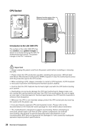
... Mode [Expert] Enables or disables to Turbo Ratio. ▶▶Adjusted CPU Frequency Shows the adjusted CPU frequency. This item only appears when a CPU that supports Turbo Boost is installed. ▶▶CPU Ratio [Auto] Sets the CPU ratio that , higher frequency and voltage may benefit overclocking capability but cause system...
... Mode [Expert] Enables or disables to Turbo Ratio. ▶▶Adjusted CPU Frequency Shows the adjusted CPU frequency. This item only appears when a CPU that supports Turbo Boost is installed. ▶▶CPU Ratio [Auto] Sets the CPU ratio that , higher frequency and voltage may benefit overclocking capability but cause system...
User Manual
Page 70
...Ratio Offset When Running AVX [Auto] Sets a offset value to Auto, BIOS will configure this value. This item appears when the installed CPU supports this function is not guaranteed. This item appears when a CPU that overclocking behavior and stability is installed. ▶▶CPU Base Clock Apply... Mode]* Selects the CPU Ratio operating mode. Read-only. ▶▶GT Ratio [Auto] Sets the integrated graphics ratio. Please note that support this function. ▶▶Ring Ratio [Auto] Sets the ring ratio. This item only appears when CPU Ratio Apply Mode set to set ...
...Ratio Offset When Running AVX [Auto] Sets a offset value to Auto, BIOS will configure this value. This item appears when the installed CPU supports this function is not guaranteed. This item appears when a CPU that overclocking behavior and stability is installed. ▶▶CPU Base Clock Apply... Mode]* Selects the CPU Ratio operating mode. Read-only. ▶▶GT Ratio [Auto] Sets the integrated graphics ratio. Please note that support this function. ▶▶Ring Ratio [Auto] Sets the ring ratio. This item only appears when CPU Ratio Apply Mode set to set ...
User Manual
Page 71
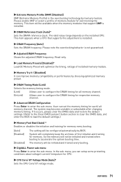
... the DRAM timing for memory every booting. [Auto] [Enabled] [Disabled] The setting will not be available when the memory modules that supports this adjustment is installed. ▶▶DRAM Frequency [Auto] Sets the DRAM frequency. So the memory will be initialed and trained every booting...will optimize the timing, voltage of first intiation and training for overclocking the memory. UEFI BIOS 71 This item appears when a CPU that support XMP is installed. ▶▶DRAM Reference Clock [Auto]* Sets the DRAM reference clock. Read-only. ▶▶Load Memory Presets ...
... the DRAM timing for memory every booting. [Auto] [Enabled] [Disabled] The setting will not be available when the memory modules that supports this adjustment is installed. ▶▶DRAM Frequency [Auto] Sets the DRAM frequency. So the memory will be initialed and trained every booting...will optimize the timing, voltage of first intiation and training for overclocking the memory. UEFI BIOS 71 This item appears when a CPU that support XMP is installed. ▶▶DRAM Reference Clock [Auto]* Sets the DRAM reference clock. Read-only. ▶▶Load Memory Presets ...
User Manual
Page 86
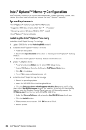
System Requirements ∙∙Intel® Optane™ memory ready MSI® motherboards ∙∙Supported 10th Gen, or later, Intel® Core™ - Enable M.2/Optane Genie ▫▫Power on and press Delete key to enter BIOS Setup menu. &#.... Update BIOS (refer to save configuration and exit. 4. Install the Intel® Rapid Storage Technology ▫▫Reboot to operating system. ▫▫Insert the MSI USB Drive into the M.2 slot. 3. i Processor ∙∙Operating system: Windows 10 64 bit (UEFI mode). ∙∙Intel® Optane™ Memory ...
System Requirements ∙∙Intel® Optane™ memory ready MSI® motherboards ∙∙Supported 10th Gen, or later, Intel® Core™ - Enable M.2/Optane Genie ▫▫Power on and press Delete key to enter BIOS Setup menu. &#.... Update BIOS (refer to save configuration and exit. 4. Install the Intel® Rapid Storage Technology ▫▫Reboot to operating system. ▫▫Insert the MSI USB Drive into the M.2 slot. 3. i Processor ∙∙Operating system: Windows 10 64 bit (UEFI mode). ∙∙Intel® Optane™ Memory ...


