User Manual
Page 13
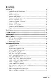
... 34 JUSB1~2: USB 2.0 Connectors 35 JTPM1: TPM Module Connector 35 CPU_FAN1, PUMP_FAN1, SYS_FAN1~6: Fan Connectors 36 JCI1: Chassis Intrusion Connector 37 JBAT1: Clear CMOS (Reset BIOS) Jumper 38 JRGB1~2: RGB LED connectors 39 Contents 13
... 34 JUSB1~2: USB 2.0 Connectors 35 JTPM1: TPM Module Connector 35 CPU_FAN1, PUMP_FAN1, SYS_FAN1~6: Fan Connectors 36 JCI1: Chassis Intrusion Connector 37 JBAT1: Clear CMOS (Reset BIOS) Jumper 38 JRGB1~2: RGB LED connectors 39 Contents 13
User Manual
Page 14
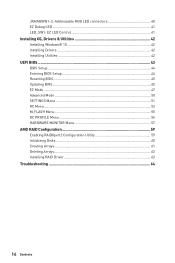
... LED Control 41 Installing OS, Drivers & Utilities 42 Installing Windows® 10 42 Installing Drivers 42 Installing Utilities 42 UEFI BIOS...43 BIOS Setup...44 Entering BIOS Setup 44 Resetting BIOS...45 Updating BIOS...45 EZ Mode ...47 Advanced Mode ...50 SETTINGS Menu 51 OC Menu...53 M-FLASH Menu ...55 OC PROFILE Menu 56 HARDWARE...
... LED Control 41 Installing OS, Drivers & Utilities 42 Installing Windows® 10 42 Installing Drivers 42 Installing Utilities 42 UEFI BIOS...43 BIOS Setup...44 Entering BIOS Setup 44 Resetting BIOS...45 Updating BIOS...45 EZ Mode ...47 Advanced Mode ...50 SETTINGS Menu 51 OC Menu...53 M-FLASH Menu ...55 OC PROFILE Menu 56 HARDWARE...
User Manual
Page 15
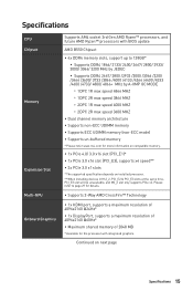
...8729;1x DisplayPort, supports a maximum resolution of 4096x2160 @60Hz* ∙∙Maximum shared memory of 2048 MB * Available for the processor with BIOS update AMD B550 Chipset ∙∙4x DDR4 memory slots, support up to 128GB* ▪▪Supports DDR4 1866/ 2133/ 2400/ 2667/ 2800/ 2933/ ...8729;Supports non-ECC UDIMM memory ∙∙Supports ECC UDIMM memory (non-ECC mode) ∙∙Supports un-buffered memory * Please refer www.msi.com for more information on compatible memory. ∙∙1x PCIe 4.0/ 3.0 x16 slot (PCI_E1)* ∙∙1x PCIe 3.0 x16 slot (PCI_E3...
...8729;1x DisplayPort, supports a maximum resolution of 4096x2160 @60Hz* ∙∙Maximum shared memory of 2048 MB * Available for the processor with BIOS update AMD B550 Chipset ∙∙4x DDR4 memory slots, support up to 128GB* ▪▪Supports DDR4 1866/ 2133/ 2400/ 2667/ 2800/ 2933/ ...8729;Supports non-ECC UDIMM memory ∙∙Supports ECC UDIMM memory (non-ECC mode) ∙∙Supports un-buffered memory * Please refer www.msi.com for more information on compatible memory. ∙∙1x PCIe 4.0/ 3.0 x16 slot (PCI_E1)* ∙∙1x PCIe 3.0 x16 slot (PCI_E3...
User Manual
Page 17
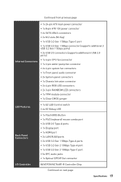
... Clear CMOS jumper LED Features ∙∙1x EZ LED Control switch ∙∙4x EZ Debug LED Back Panel Connectors ∙∙1x Flash BIOS Button ∙∙1x PS/2 keyboard/ mouse combo port ∙∙2x USB 2.0 Type-A ports ∙∙1x Display port ∙∙1x HDMI port...
... Clear CMOS jumper LED Features ∙∙1x EZ LED Control switch ∙∙4x EZ Debug LED Back Panel Connectors ∙∙1x Flash BIOS Button ∙∙1x PS/2 keyboard/ mouse combo port ∙∙2x USB 2.0 Type-A ports ∙∙1x Display port ∙∙1x HDMI port...
User Manual
Page 18
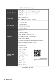
... Specifications x 9.6 in . com/manual/mb/DRAGONCENTER2. pdf for more details. Continued from previous page Hardware Monitor Form Factor BIOS Features Software Dragon Center Features ∙∙CPU/ System/ Chipset temperature detection ∙∙CPU/ System/ Pump fan speed ...Mb flash ∙∙UEFI AMI BIOS ∙∙ACPI 6.0, SMBIOS 2.8 ∙∙ Multi-language ∙∙ Drivers ∙∙DRAGON CENTER ∙∙MSI APP Player (BlueStacks) ∙∙Open Broadcaster Software (OBS) ∙∙CPU-Z MSI GAMING ∙∙Google Chrome™,...
... Specifications x 9.6 in . com/manual/mb/DRAGONCENTER2. pdf for more details. Continued from previous page Hardware Monitor Form Factor BIOS Features Software Dragon Center Features ∙∙CPU/ System/ Chipset temperature detection ∙∙CPU/ System/ Pump fan speed ...Mb flash ∙∙UEFI AMI BIOS ∙∙ACPI 6.0, SMBIOS 2.8 ∙∙ Multi-language ∙∙ Drivers ∙∙DRAGON CENTER ∙∙MSI APP Player (BlueStacks) ∙∙Open Broadcaster Software (OBS) ∙∙CPU-Z MSI GAMING ∙∙Google Chrome™,...

User Manual
Page 19
... ▪▪PCI-E Steel Armor ▪▪PCI-E Steel Slot ▪▪Pre-installed I/O Shielding ∙∙ Experience ▪▪Dragon Center ▪▪Click BIOS 5 ▪▪Flash BIOS Button Specifications 19
... ▪▪PCI-E Steel Armor ▪▪PCI-E Steel Slot ▪▪Pre-installed I/O Shielding ∙∙ Experience ▪▪Dragon Center ▪▪Click BIOS 5 ▪▪Flash BIOS Button Specifications 19
User Manual
Page 22
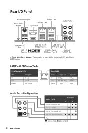
... 100/ 1000 Mbps 2.5 Gbps 10 Mbps 100 Mbps 1 Gbps Audio Ports Configuration 22 Rear I /O Panel PS/2 Combo port 1 Gbps LAN Flash BIOS Button 2.5 Gbps LAN DisplayPort Audio Ports Flash BIOS Port USB 2.0 Type-A USB 3.2 Gen 1 (5Gbps) Type-A USB 3.2 Gen 2 (10Gbps) Type-A USB 3.2 Gen 2 (10Gbps) Type-C ...Optical S/PDIF-Out ∙∙ Flash BIOS Port/ Button - Rear I /O Panel Audio Ports Channel 2468 Center/ Sub-woofer Out ●● Rear Speaker Out ●●● Line-In/ Side...
... 100/ 1000 Mbps 2.5 Gbps 10 Mbps 100 Mbps 1 Gbps Audio Ports Configuration 22 Rear I /O Panel PS/2 Combo port 1 Gbps LAN Flash BIOS Button 2.5 Gbps LAN DisplayPort Audio Ports Flash BIOS Port USB 2.0 Type-A USB 3.2 Gen 1 (5Gbps) Type-A USB 3.2 Gen 2 (10Gbps) Type-A USB 3.2 Gen 2 (10Gbps) Type-C ...Optical S/PDIF-Out ∙∙ Flash BIOS Port/ Button - Rear I /O Panel Audio Ports Channel 2468 Center/ Sub-woofer Out ●● Rear Speaker Out ●●● Line-In/ Side...
User Manual
Page 26
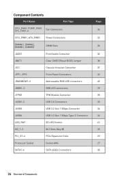
... Port Type CPU_FAN1, PUMP_FAN1, SYS_FAN1~6 Fan Connectors CPU_PWR1, ATX_PWR1 Power Connectors DIMMA1, DIMMA2, DIMMB1, DIMMB2 DIMM Slots JAUD1 Front Audio Connector JBAT1 Clear CMOS (Reset BIOS) Jumper JCI1 Chassis Intrusion Connector JFP1, JFP2 Front Panel Connectors JRAINBOW1~2 Addressable RGB LED connectors JRGB1~2 RGB LED connectors JTPM1 TPM Module Connector JUSB1~2 USB...
... Port Type CPU_FAN1, PUMP_FAN1, SYS_FAN1~6 Fan Connectors CPU_PWR1, ATX_PWR1 Power Connectors DIMMA1, DIMMA2, DIMMB1, DIMMB2 DIMM Slots JAUD1 Front Audio Connector JBAT1 Clear CMOS (Reset BIOS) Jumper JCI1 Chassis Intrusion Connector JFP1, JFP2 Front Panel Connectors JRAINBOW1~2 Addressable RGB LED connectors JRGB1~2 RGB LED connectors JTPM1 TPM Module Connector JUSB1~2 USB...
User Manual
Page 27
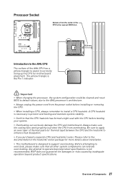
...the heatsink/ cooler package for motherboard placement. Overview of the AM4 CPU has a yellow triangle to install a CPU heatsink. MSI® does not guarantee the damages or risks caused by inadequate operation beyond product specifications is designed to the documentation in correctly ...is the Pin 1 indicator. ⚠⚠Important ∙∙When changing the processor, the system configuration could be cleared and reset BIOS to default values, due to operate beyond product specifications. Any attempt to the AM4 processor's architecture. ∙∙Always unplug the power...
...the heatsink/ cooler package for motherboard placement. Overview of the AM4 CPU has a yellow triangle to install a CPU heatsink. MSI® does not guarantee the damages or risks caused by inadequate operation beyond product specifications is designed to the documentation in correctly ...is the Pin 1 indicator. ⚠⚠Important ∙∙When changing the processor, the system configuration could be cleared and reset BIOS to default values, due to operate beyond product specifications. Any attempt to the AM4 processor's architecture. ∙∙Always unplug the power...
User Manual
Page 28
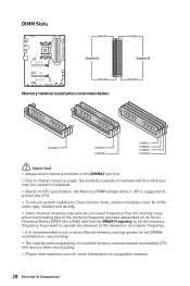
... overclocking due to use a more efficient memory cooling system for full DIMMs installation or overclocking. ∙∙The stability and compatibility of Components Go to BIOS and find the DRAM Frequency to set the memory frequency if you want to operate the memory at the marked or at a lower frequency than... frequency operates dependent on compatible memory. 28 Overview of installed memory module depend on installed CPU and devices when overclocking. ∙∙Please refer www.msi.com for more information on its Serial Presence Detect (SPD).
... overclocking due to use a more efficient memory cooling system for full DIMMs installation or overclocking. ∙∙The stability and compatibility of Components Go to BIOS and find the DRAM Frequency to set the memory frequency if you want to operate the memory at the marked or at a lower frequency than... frequency operates dependent on compatible memory. 28 Overview of installed memory module depend on installed CPU and devices when overclocking. ∙∙Please refer www.msi.com for more information on its Serial Presence Detect (SPD).
User Manual
Page 36
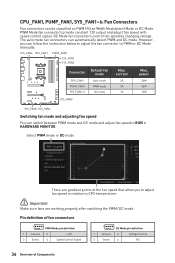
DC Mode fan connectors control fan speed by changing voltage. However, you to adjust fan speed in BIOS > HARDWARE MONITOR. PWM Mode fan connectors provide constant 12V output and adjust fan speed with speed control signal. SYS_FAN6 CPU_FAN1 PUMP_FAN1 SYS_FAN1 SYS_FAN2 Connector CPU_FAN1 ...
DC Mode fan connectors control fan speed by changing voltage. However, you to adjust fan speed in BIOS > HARDWARE MONITOR. PWM Mode fan connectors provide constant 12V output and adjust fan speed with speed control signal. SYS_FAN6 CPU_FAN1 PUMP_FAN1 SYS_FAN1 SYS_FAN2 Connector CPU_FAN1 ...
User Manual
Page 37
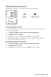
Connect the JCI1 connector to select Yes. 6. Go to BIOS > SETTINGS > Security > Chassis Intrusion Configuration. 2. Once the chassis cover is opened again, a warning message will be displayed on screen when the computer is turned... Using chassis intrusion detector 1. Press F10 to save and exit and then press the Enter key to connect the chassis intrusion switch cable. Go to BIOS > SETTINGS > Security > Chassis Intrusion Configuration. 4. Set Chassis Intrusion to Enabled. 5. Set Chassis Intrusion to Reset. 3. Overview of Components 37 JCI1: Chassis Intrusion Connector ...
Connect the JCI1 connector to select Yes. 6. Go to BIOS > SETTINGS > Security > Chassis Intrusion Configuration. 2. Once the chassis cover is opened again, a warning message will be displayed on screen when the computer is turned... Using chassis intrusion detector 1. Press F10 to save and exit and then press the Enter key to connect the chassis intrusion switch cable. Go to BIOS > SETTINGS > Security > Chassis Intrusion Configuration. 4. Set Chassis Intrusion to Enabled. 5. Set Chassis Intrusion to Reset. 3. Overview of Components 37 JCI1: Chassis Intrusion Connector ...
User Manual
Page 38
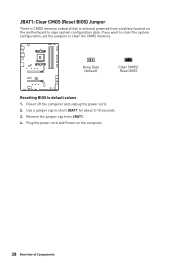
If you want to clear the system configuration, set the jumpers to default values 1. Keep Data (default) Clear CMOS/ Reset BIOS Resetting BIOS to clear the CMOS memory. Remove the jumper cap from a battery located on the computer. 38 Overview of Components Use a jumper cap to save system configuration data. Plug the power cord and Power on the motherboard to short JBAT1 for about 5-10 seconds. 3. Power off the computer and unplug the power cord. 2. JBAT1: Clear CMOS (Reset BIOS) Jumper There is CMOS memory onboard that is external powered from JBAT1. 4.
If you want to clear the system configuration, set the jumpers to default values 1. Keep Data (default) Clear CMOS/ Reset BIOS Resetting BIOS to clear the CMOS memory. Remove the jumper cap from a battery located on the computer. 38 Overview of Components Use a jumper cap to save system configuration data. Plug the power cord and Power on the motherboard to short JBAT1 for about 5-10 seconds. 3. Power off the computer and unplug the power cord. 2. JBAT1: Clear CMOS (Reset BIOS) Jumper There is CMOS memory onboard that is external powered from JBAT1. 4.
User Manual
Page 43
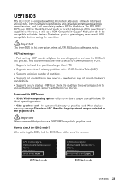
... (Compatibility Support Module) mode to use a GOP/ UEFI compatible graphics card. The MSI UEFI BIOS uses UEFI as the default boot mode to check the BIOS mode? After entering the BIOS, find the BIOS Mode at the top of new devices - UEFI BIOS MSI UEFI BIOS is no malware tampers with a GUID Partition Table (GPT). ∙∙Supports...
... (Compatibility Support Module) mode to use a GOP/ UEFI compatible graphics card. The MSI UEFI BIOS uses UEFI as the default boot mode to check the BIOS mode? After entering the BIOS, find the BIOS Mode at the top of new devices - UEFI BIOS MSI UEFI BIOS is no malware tampers with a GUID Partition Table (GPT). ∙∙Supports...
User Manual
Page 44
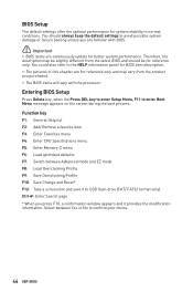
...CPU Specifications menu F5: Enter Memory-Z menu F6: Load optimized defaults F7: Switch between Yes or No to the HELP information panel for BIOS item description. ∙∙The pictures in normal conditions. Select between Advanced mode and EZ mode F8: Load Overclocking Profile F9: Save ...provides the modification information. Ctrl+F: Enter Search page * When you are for reference only and may be slightly different from the latest BIOS and should always keep the default settings to enter Boot Menu message appears on the screen during the boot process. Therefore, the description...
...CPU Specifications menu F5: Enter Memory-Z menu F6: Load optimized defaults F7: Switch between Yes or No to the HELP information panel for BIOS item description. ∙∙The pictures in normal conditions. Select between Advanced mode and EZ mode F8: Load Overclocking Profile F9: Save ...provides the modification information. Ctrl+F: Enter Search page * When you are for reference only and may be slightly different from the latest BIOS and should always keep the default settings to enter Boot Menu message appears on the screen during the boot process. Therefore, the description...
User Manual
Page 45
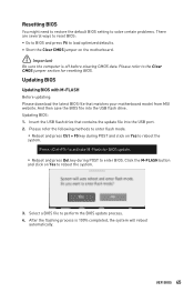
... POST and click on Yes to perform the BIOS update process. 4. Select a BIOS file to reboot the system. 3. And then save the BIOS file into the USB port. 2. Insert the USB flash drive that matches your motherboard model from MSI website. After the flashing process is off before... clearing CMOS data. Click the M-FLASH button and click on Yes to the Clear CMOS jumper section for resetting BIOS. Updating BIOS Updating BIOS with M-FLASH Before updating: Please download the latest BIOS file that contains ...
... POST and click on Yes to perform the BIOS update process. 4. Select a BIOS file to reboot the system. 3. And then save the BIOS file into the USB port. 2. Insert the USB flash drive that matches your motherboard model from MSI website. After the flashing process is off before... clearing CMOS data. Click the M-FLASH button and click on Yes to the Clear CMOS jumper section for resetting BIOS. Updating BIOS Updating BIOS with M-FLASH Before updating: Please download the latest BIOS file that contains ...
User Manual
Page 46
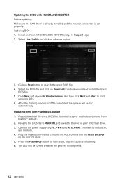
... motherboard model from the MSI® website. 2. Press the Flash BIOS Button to Support page. 2. Install and launch MSI DRAGON CENTER and go to flash BIOS, and the LED starts flashing. 6. Click on Download icon to search the latest BIOS file. 4. Select the BIOS file and click on ...Scan button to download and install the latest BIOS file. 5. After the flashing process is completed. 46 UEFI BIOS Please download the latest BIOS file that contains the MSI.ROM file into the Flash BIOS Port on Advance button. 3. Updating BIOS with MSI DRAGON CENTER Before updating: Make sure the ...
... motherboard model from the MSI® website. 2. Press the Flash BIOS Button to Support page. 2. Install and launch MSI DRAGON CENTER and go to flash BIOS, and the LED starts flashing. 6. Click on Download icon to search the latest BIOS file. 4. Select the BIOS file and click on ...Scan button to download and install the latest BIOS file. 5. After the flashing process is completed. 46 UEFI BIOS Please download the latest BIOS file that contains the MSI.ROM file into the Flash BIOS Port on Advance button. 3. Updating BIOS with MSI DRAGON CENTER Before updating: Make sure the ...
User Manual
Page 47
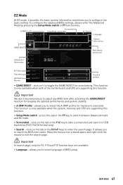
... buttons ∙∙ GAME BOOST - allows you to select the A-XMP profile for overclocking. To configure the advanced BIOS settings, please enter the Advanced Mode by BIOS item name. press this tab or the F12 key to take a screenshot and save it to configure the basic setting...drive (FAT/ FAT32 format only). ∙∙ Search - click on this function. ⚠⚠Important We don't recommend you to adjust any BIOS item after activating the GAME BOOST function for keeping the optimal performance and system stability. ∙∙ A-XMP Profile - It allows you to ...
... buttons ∙∙ GAME BOOST - allows you to select the A-XMP profile for overclocking. To configure the advanced BIOS settings, please enter the Advanced Mode by BIOS item name. press this tab or the F12 key to take a screenshot and save it to configure the basic setting...drive (FAT/ FAT32 format only). ∙∙ Search - click on this function. ⚠⚠Important We don't recommend you to adjust any BIOS item after activating the GAME BOOST function for keeping the optimal performance and system stability. ∙∙ A-XMP Profile - It allows you to ...
User Manual
Page 48
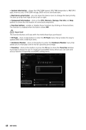
...;Important The function buttons will vary with a USB flash drive. ∙∙ Hardware Monitor - The boot priority from high to create personal BIOS menu where you purchased. ∙∙ M-Flash - The function is left to show the information of connected component. ∙∙ Function ..., Fan Info and Help buttons to enter the M-Flash menu that allows you can save and access favorite/ frequently-used BIOS setting items. 48 UEFI BIOS click on these functions by percentage. ∙∙ Favorites - ∙∙ System information - you to manually control ...
...;Important The function buttons will vary with a USB flash drive. ∙∙ Hardware Monitor - The boot priority from high to create personal BIOS menu where you purchased. ∙∙ M-Flash - The function is left to show the information of connected component. ∙∙ Function ..., Fan Info and Help buttons to enter the M-Flash menu that allows you can save and access favorite/ frequently-used BIOS setting items. 48 UEFI BIOS click on these functions by percentage. ∙∙ Favorites - ∙∙ System information - you to manually control ...
User Manual
Page 49
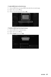
Right-click or press F2 key. 3. Select a BIOS item on OK. Choose Delete and click on favorite menu. 2. UEFI BIOS 49 Right-click or press F2 key. 3. Choose a favorite page and click on search page. 2. ▪▪To add a BIOS item to a favorite menu 1. Select a BIOS item not only on BIOS menu but also on OK. ▪▪To delete a BIOS item from favorite menu 1.
Right-click or press F2 key. 3. Select a BIOS item on OK. Choose Delete and click on favorite menu. 2. UEFI BIOS 49 Right-click or press F2 key. 3. Choose a favorite page and click on search page. 2. ▪▪To add a BIOS item to a favorite menu 1. Select a BIOS item not only on BIOS menu but also on OK. ▪▪To delete a BIOS item from favorite menu 1.


