

User Guide
Page 2
... harmful interference to comply with the limits for a class B digital device, pursuant to provide reasonable protection against harmful interference in a residential installation. Micro-Star International MS-7207 ii power cord, if any, must be determined by turning the equipment off and on, the user is encouraged to try to correct the interference...
... harmful interference to comply with the limits for a class B digital device, pursuant to provide reasonable protection against harmful interference in a residential installation. Micro-Star International MS-7207 ii power cord, if any, must be determined by turning the equipment off and on, the user is encouraged to try to correct the interference...

User Guide
Page 12
Designed to fit the advanced AMD® K8 Athlon 64 FX processor, the K8NGM2 Series deliver a high performance and professional desktop platform solution. 1-1 The K8NGM2 Series mainboards are based on nVidia® GeForce 6150/6100 & nVidia® nForce 430/410 chipsets for choosing the K8NGM2 Series (MS-7207 v2.X) Micro ATX mainboard. Getting Started Getting Started Thank you for optimal system efficiency. Getting Started Chapter 1.
Designed to fit the advanced AMD® K8 Athlon 64 FX processor, the K8NGM2 Series deliver a high performance and professional desktop platform solution. 1-1 The K8NGM2 Series mainboards are based on nVidia® GeForce 6150/6100 & nVidia® nForce 430/410 chipsets for choosing the K8NGM2 Series (MS-7207 v2.X) Micro ATX mainboard. Getting Started Getting Started Thank you for optimal system efficiency. Getting Started Chapter 1.

User Guide
Page 13
...8 ports. - nForce 430 supports RAID 0, 1, 0+1,and 5, nForce 410 supports RAID 0, 1 only. - Supports USB2.0 up to 4 IDE devices. MS-7207 M-ATX Mainboard Mainboard Specifications CPU † Supports 64-bit AMD® K8 Athlon64/ Athlon64FX processor (Socket 939). † Supports 4800+ and higher CPU.... for dual channel. † Supports a maximum memory size of 4GB. (For the updated supporting memory modules, please visit http://www.msi.com. HyperTransportTM connection to 300MB/s transfer rate (nForce 410 supports 2 Serial ATAII ports only). Supports HD audio. Graphic integrated. †...
...8 ports. - nForce 430 supports RAID 0, 1, 0+1,and 5, nForce 410 supports RAID 0, 1 only. - Supports USB2.0 up to 4 IDE devices. MS-7207 M-ATX Mainboard Mainboard Specifications CPU † Supports 64-bit AMD® K8 Athlon64/ Athlon64FX processor (Socket 939). † Supports 4800+ and higher CPU.... for dual channel. † Supports a maximum memory size of 4GB. (For the updated supporting memory modules, please visit http://www.msi.com. HyperTransportTM connection to 300MB/s transfer rate (nForce 410 supports 2 Serial ATAII ports only). Supports HD audio. Graphic integrated. †...
User Guide
Page 15
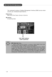
Dimension † Micro-ATX Form Factor: 24.4cm X 24.4cm Mounting † 8 mounting holes 1394 GUID address Label (optional) MSI Reminds You... 1. If the 1394 GUID address is burnt in the system BIOS. 2. The 1394 GUID address is lost due to recover its original ...in the BIOS core. Use the flash utility or Live Update from MSI's website by entering the 1394 GUID address to an unpredictable event, such as replacing a new BIOS chip, users can use the utility from MSI's website for BIOS update. MS-7207 M-ATX Mainboard † The mainboard provides a Desktop Management Interface (...
Dimension † Micro-ATX Form Factor: 24.4cm X 24.4cm Mounting † 8 mounting holes 1394 GUID address Label (optional) MSI Reminds You... 1. If the 1394 GUID address is burnt in the system BIOS. 2. The 1394 GUID address is lost due to recover its original ...in the BIOS core. Use the flash utility or Live Update from MSI's website by entering the 1394 GUID address to an unpredictable event, such as replacing a new BIOS chip, users can use the utility from MSI's website for BIOS update. MS-7207 M-ATX Mainboard † The mainboard provides a Desktop Management Interface (...

User Guide
Page 16
Getting Started Mainboard Layout K8NGM2 Series (MS-7207 v2.X) M-ATX Mainboard 1-5
Getting Started Mainboard Layout K8NGM2 Series (MS-7207 v2.X) M-ATX Mainboard 1-5

User Guide
Page 17
Your packing contents may vary depending on the model you purchased. 1-6 MS-7207 M-ATX Mainboard Packing Checklist MSI motherboard MSI Driver/Utility CD SATA Cable (Optional) Power Cable (Optional) Standard Cable for Floppy Disk Standard Cable for IDE Devices 1394 Bracket (Optional) USB Bracket (Optional) Back IO Shield User's Guide TV-out Bracket (Optional) Audio-out Bracket (Optional) * The pictures are for reference only.
Your packing contents may vary depending on the model you purchased. 1-6 MS-7207 M-ATX Mainboard Packing Checklist MSI motherboard MSI Driver/Utility CD SATA Cable (Optional) Power Cable (Optional) Standard Cable for Floppy Disk Standard Cable for IDE Devices 1394 Bracket (Optional) USB Bracket (Optional) Back IO Shield User's Guide TV-out Bracket (Optional) Audio-out Bracket (Optional) * The pictures are for reference only.

User Guide
Page 21
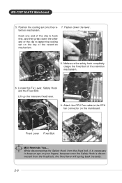
... mainboard. Please note that any violation of the correct installation procedures may cause permanent damages to a 90-degree angle. The CPU can not be seen. MS-7207 M-ATX Mainboard CPU Installation Procedures for the gold arrow of the CPU. Pull the lever sideways away from the socket. Please turn off the power...
... mainboard. Please note that any violation of the correct installation procedures may cause permanent damages to a 90-degree angle. The CPU can not be seen. MS-7207 M-ATX Mainboard CPU Installation Procedures for the gold arrow of the CPU. Pull the lever sideways away from the socket. Please turn off the power...
User Guide
Page 23
Hook one end of the clip to fasten the cooling set onto the re- 7. Safety Hook 9. Fixed Lever Fixed Bolt MSI Reminds You... MS-7207 M-ATX Mainboard 5. Make sure the safety hook completely clasps the fixed bolt of the retention mechanism. 8. While disconnecting the Safety Hook from the fixed bolt, ...
Hook one end of the clip to fasten the cooling set onto the re- 7. Safety Hook 9. Fixed Lever Fixed Bolt MSI Reminds You... MS-7207 M-ATX Mainboard 5. Make sure the safety hook completely clasps the fixed bolt of the retention mechanism. 8. While disconnecting the Safety Hook from the fixed bolt, ...

User Guide
Page 25
Volt Notch 2-8 Insert the DIMM memory module vertically into the DIMM slot. The DDR DIMM has only one notch on the memory module is deeply inserted in the right orientation. 2. The module will automatically close. The plastic clip at each side of module. Then push it in until the golden finger on the center of the DIMM slot will only fit in the socket. 3. MS-7207 M-ATX Mainboard Installing DDR Modules 1.
Volt Notch 2-8 Insert the DIMM memory module vertically into the DIMM slot. The DDR DIMM has only one notch on the memory module is deeply inserted in the right orientation. 2. The module will automatically close. The plastic clip at each side of module. Then push it in until the golden finger on the center of the DIMM slot will only fit in the socket. 3. MS-7207 M-ATX Mainboard Installing DDR Modules 1.

User Guide
Page 27
... 10 GND 11 N/C 12 SDA 13 Horizontal Sync 14 Vertical Sync 15 SCL 2-10 You can plug a PS/2® mouse/keyboard directly into this connector. MS-7207 M-ATX Mainboard Mouse Back Panel Parallel 1394 Port L-In LAN (Optional) Keyboard DVI Port (for GeForce 6150) (optional) VGA Port USB Ports USB L-Out Ports...
... 10 GND 11 N/C 12 SDA 13 Horizontal Sync 14 Vertical Sync 15 SCL 2-10 You can plug a PS/2® mouse/keyboard directly into this connector. MS-7207 M-ATX Mainboard Mouse Back Panel Parallel 1394 Port L-In LAN (Optional) Keyboard DVI Port (for GeForce 6150) (optional) VGA Port USB Ports USB L-Out Ports...

User Guide
Page 29
.... This LAN enables data to the following for VSC8201RX only). The computer is communicating with another computer on the transfer rates: 10/100Mbps or 1000Mbps. MS-7207 M-ATX Mainboard LAN (RJ-45) Jack:10/100 LAN (RTL8201CL) or Giga-bit LAN (VSC8201RX : optional) The mainboard provides 1 standard RJ-45 jack for connection...
.... This LAN enables data to the following for VSC8201RX only). The computer is communicating with another computer on the transfer rates: 10/100Mbps or 1000Mbps. MS-7207 M-ATX Mainboard LAN (RJ-45) Jack:10/100 LAN (RTL8201CL) or Giga-bit LAN (VSC8201RX : optional) The mainboard provides 1 standard RJ-45 jack for connection...

User Guide
Page 31
MS-7207 M-ATX Mainboard Parallel Port Connector: LPT1 The mainboard provides a 25-pin female centronic connector as LPT. A parallel port is a standard printer port that supports Enhanced ...
MS-7207 M-ATX Mainboard Parallel Port Connector: LPT1 The mainboard provides a 25-pin female centronic connector as LPT. A parallel port is a standard printer port that supports Enhanced ...

User Guide
Page 33
MSI Reminds You... You must configure the second drive to the hard disk documentation supplied by setting the jumper accordingly. Refer to Slave mode by setting ..., you must configure second hard drive to four hard disk drives, CD-ROM and other IDE devices. IDE1 can also connect a Master and a Slave drive. MS-7207 M-ATX Mainboard ATA133 Hard Disk Connectors: IDE1 & IDE2 The mainboard has a 32-bit Enhanced PCI IDE and Ultra DMA 66/100/133 controller that provides...
MSI Reminds You... You must configure the second drive to the hard disk documentation supplied by setting the jumper accordingly. Refer to Slave mode by setting ..., you must configure second hard drive to four hard disk drives, CD-ROM and other IDE devices. IDE1 can also connect a Master and a Slave drive. MS-7207 M-ATX Mainboard ATA133 Hard Disk Connectors: IDE1 & IDE2 The mainboard has a 32-bit Enhanced PCI IDE and Ultra DMA 66/100/133 controller that provides...

User Guide
Page 35
... Connector Key 9 PORT 2L Analog Port 2 - To clear the warning, you to connect to the front panel audio and is connected to a 2-pin chassis switch. MS-7207 M-ATX Mainboard CD-In Connector: JCD1 This connector is connected to the analog header. signals BIOS that a High Definition Audio dongle is compliant with Intel...
... Connector Key 9 PORT 2L Analog Port 2 - To clear the warning, you to connect to the front panel audio and is connected to a 2-pin chassis switch. MS-7207 M-ATX Mainboard CD-In Connector: JCD1 This connector is connected to the analog header. signals BIOS that a High Definition Audio dongle is compliant with Intel...

User Guide
Page 37
... is a 16550A high speed communication port that allows you to connect IEEE 1394 ports via an external IEEE1394 bracket (optional). 9 1 10 2 J1394_1 Connected to it. MS-7207 M-ATX Mainboard Serial Port Header: JCOM1 (Optional) The mainboard offers one 1394 pin header that sends/receives 16 bytes FIFOs.
... is a 16550A high speed communication port that allows you to connect IEEE 1394 ports via an external IEEE1394 bracket (optional). 9 1 10 2 J1394_1 Connected to it. MS-7207 M-ATX Mainboard Serial Port Header: JCOM1 (Optional) The mainboard offers one 1394 pin header that sends/receives 16 bytes FIFOs.

User Guide
Page 39
... Description Pin Description 1 GND 4 COMP 2 Yout 5 GND 3 Cout Connected to JTV1 TV-Out Bracket (Optional) TV-Out Connector TV-Out Connector (RCA Composite) (S-Video) MSI Reminds You... 1. MS-7207 M-ATX Mainboard TV-Out Connector: JTV1 (For GeForce 6150 Only, Optional) The mainboard optionally provides a TV-Out connector for details. 2-22 Otherwise, the TVs...
... Description Pin Description 1 GND 4 COMP 2 Yout 5 GND 3 Cout Connected to JTV1 TV-Out Bracket (Optional) TV-Out Connector TV-Out Connector (RCA Composite) (S-Video) MSI Reminds You... 1. MS-7207 M-ATX Mainboard TV-Out Connector: JTV1 (For GeForce 6150 Only, Optional) The mainboard optionally provides a TV-Out connector for details. 2-22 Otherwise, the TVs...

User Guide
Page 41
... external battery to clear the data. W ith the CMOS RAM, the system can automatically boot OS every time it is a CMOS RAM on . SW1 2-24 MS-7207 M-ATX Mainboard Button The motherboard provides the following button for you want to clear the system configuration, use the SW 1 (Clear CMOS Button ) to set...
... external battery to clear the data. W ith the CMOS RAM, the system can automatically boot OS every time it is a CMOS RAM on . SW1 2-24 MS-7207 M-ATX Mainboard Button The motherboard provides the following button for you want to clear the system configuration, use the SW 1 (Clear CMOS Button ) to set...

User Guide
Page 44
MS-7207 M-ATX Mainboard Entering Setup Power on the screen, press key to the main menu from a submenu Increase the numeric value or make changes Decrease the ...
MS-7207 M-ATX Mainboard Entering Setup Power on the screen, press key to the main menu from a submenu Increase the numeric value or make changes Decrease the ...
User Guide
Page 46
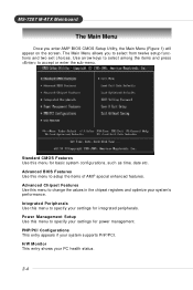
... select among the items and press to select from twelve setup functions and two exit choices. H/W Monitor This entry shows your system supports PnP/PCI. MS-7207 M-ATX Mainboard The Main Menu Once you to accept or enter the sub-menu. Advanced BIOS Features Use this menu to specify your system's performance...
... select among the items and press to select from twelve setup functions and two exit choices. H/W Monitor This entry shows your system supports PnP/PCI. MS-7207 M-ATX Mainboard The Main Menu Once you to accept or enter the sub-menu. Advanced BIOS Features Use this menu to specify your system's performance...

User Guide
Page 48
MS-7207 M-ATX Mainboard Standard CMOS Features The items in each item: 3-6 date The date from Jan. Primary/Secondary IDE Master/ Slave, Serial-ATA 1/2 Primary/Secondary Press ...
MS-7207 M-ATX Mainboard Standard CMOS Features The items in each item: 3-6 date The date from Jan. Primary/Secondary IDE Master/ Slave, Serial-ATA 1/2 Primary/Secondary Press ...


