User Guide
Page 5
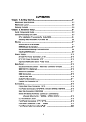
... 2. Hardware Setup 2-1 Quick Components Guide 2-2 Central Processing Unit: CPU 2-3 CPU Installation Procedures for Socket 939 2-4 Installing AMD Athlon64 CPU Cooler Set 2-5 Memory ...2-7 Introduction to DDR SDRAM 2-7 DIMM Module Combination 2-7 Recommended Memory Combination List 2-8 Installing DDR Modules 2-9 Power Supply 2-10 ATX 20-Pin Power Connector: ATX1 2-10 ATX 12V Power Connector: JPW1 2-10 Important Notification about...
... 2. Hardware Setup 2-1 Quick Components Guide 2-2 Central Processing Unit: CPU 2-3 CPU Installation Procedures for Socket 939 2-4 Installing AMD Athlon64 CPU Cooler Set 2-5 Memory ...2-7 Introduction to DDR SDRAM 2-7 DIMM Module Combination 2-7 Recommended Memory Combination List 2-8 Installing DDR Modules 2-9 Power Supply 2-10 ATX 20-Pin Power Connector: ATX1 2-10 ATX 12V Power Connector: JPW1 2-10 Important Notification about...
User Guide
Page 9
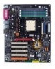
... the latest information about CPU, please visit http://www.msi.com.tw/program/ products/mainboard/mbd/pro_mbd_cpu_support.php) Chipset h nVIDIA nForce3 Ultra - IEEE 802.3 nVIDIA MAC for four drives - AGP specification compliant - MS-7025 ATX Mainboard Mainboard Specifications CPU h Supports Socket-939 for AMD K8 Athlon 64 FX / Athlon 64 (Socket939) processor h Supports up...
... the latest information about CPU, please visit http://www.msi.com.tw/program/ products/mainboard/mbd/pro_mbd_cpu_support.php) Chipset h nVIDIA nForce3 Ultra - IEEE 802.3 nVIDIA MAC for four drives - AGP specification compliant - MS-7025 ATX Mainboard Mainboard Specifications CPU h Supports Socket-939 for AMD K8 Athlon 64 FX / Athlon 64 (Socket939) processor h Supports up...

User Guide
Page 14
While doing the installation, be careful in holding the components and follow the installation procedures. 2-1 Also, it provides the instructions on connecting the peripheral devices, such as how to setup the jumpers on the mainboard. Hardware Setup Hardware Setup This chapter tells you how to install the CPU, memory modules, and expansion cards, as well as the mouse, keyboard, etc. Hardware Setup Chapter 2.
While doing the installation, be careful in holding the components and follow the installation procedures. 2-1 Also, it provides the instructions on connecting the peripheral devices, such as how to setup the jumpers on the mainboard. Hardware Setup Hardware Setup This chapter tells you how to install the CPU, memory modules, and expansion cards, as well as the mouse, keyboard, etc. Hardware Setup Chapter 2.

User Guide
Page 16
... the cooling fan can work properly to support overclocking. Overclocking This motherboard is not recommended. For the latest information about CPU, please visit http://www.msi.com.tw/program/ products/mainboard/mbd/pro_mbd_cpu_support.php. Replacing the CPU While replacing the CPU, always turn off the ATX power supply or unplug the power supply's power cord from...
... the cooling fan can work properly to support overclocking. Overclocking This motherboard is not recommended. For the latest information about CPU, please visit http://www.msi.com.tw/program/ products/mainboard/mbd/pro_mbd_cpu_support.php. Replacing the CPU While replacing the CPU, always turn off the ATX power supply or unplug the power supply's power cord from...
User Guide
Page 17
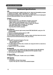
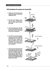
MS-7025 ATX Mainboard CPU Installation Procedures for the gold arrow. Make sure to raise the lever up to your fingers pressing tightly on top of the correct installation procedures may cause permanent damages to a 90-degree angle. 3. Press the CPU down firmly into the socket and can only fit...correctly installed, the pins should point towards the lever pivot. Please note that any violation of the CPU to make sure the CPU is being closed, always close the lever. As the CPU is likely to move while the lever is properly and completely embedded into the socket. 2-4 The ...
MS-7025 ATX Mainboard CPU Installation Procedures for the gold arrow. Make sure to raise the lever up to your fingers pressing tightly on top of the correct installation procedures may cause permanent damages to a 90-degree angle. 3. Press the CPU down firmly into the socket and can only fit...correctly installed, the pins should point towards the lever pivot. Please note that any violation of the CPU to make sure the CPU is being closed, always close the lever. As the CPU is likely to move while the lever is properly and completely embedded into the socket. 2-4 The ...

User Guide
Page 18
Hardware Setup Installing AMD Athlon64 CPU Cooler Set When you do not have the heat sink and cooling fan, contact your dealer to purchase and install them before turning on the ... two screws. retention mechanism 2-5 Detach the shield of the mainboard. 2. Locate the two screw holes of the backplate's 3. If you are installing the CPU, make sure the CPU has a heat sink and a cooling fan attached on the flat surface. place the mainboard on the top to the proper position. 4. Align the retention...
Hardware Setup Installing AMD Athlon64 CPU Cooler Set When you do not have the heat sink and cooling fan, contact your dealer to purchase and install them before turning on the ... two screws. retention mechanism 2-5 Detach the shield of the mainboard. 2. Locate the two screw holes of the backplate's 3. If you are installing the CPU, make sure the CPU has a heat sink and a cooling fan attached on the flat surface. place the mainboard on the top to the proper position. 4. Align the retention...

User Guide
Page 19
tention mechanism. Hook one end of the retention mechanism. 8. While disconnecting the Safety Hook from the fixed bolt, it is necessary to the CPU fan connector on your fingers, because once the Safety Hook is disconnected from the fixed bolt, the fixed lever will spring back instantly. 2-6...Locate the Fix Lever, Safety Hook and the Fixed Bolt. Attach the CPU Fan cable to keep an eye on the mainboard. Fixed Lever Fixed Bolt MSI Reminds You... Lift up the intensive fixed lever. Safety Hook 9. MS-7025 ATX Mainboard 5. Position the cooling set on the top of the clip to ...
tention mechanism. Hook one end of the retention mechanism. 8. While disconnecting the Safety Hook from the fixed bolt, it is necessary to the CPU fan connector on your fingers, because once the Safety Hook is disconnected from the fixed bolt, the fixed lever will spring back instantly. 2-6...Locate the Fix Lever, Safety Hook and the Fixed Bolt. Attach the CPU Fan cable to keep an eye on the mainboard. Fixed Lever Fixed Bolt MSI Reminds You... Lift up the intensive fixed lever. Safety Hook 9. MS-7025 ATX Mainboard 5. Position the cooling set on the top of the clip to ...

User Guide
Page 23
Power supply of 300 (and up) watt is used to provide power to the CPU. 10 20 1 11 ATX1 ATX1 Pin Definition PIN SIGNAL PIN 1 3.3V 11 2 3.3V 12 3 GND 13 4 5V 14 5 GND 15 6 5V 16 7 GND 17 8 PW_OK ... 20 SIGNAL 3.3V -12V GND PS_ON GND GND GND -5V 5V 5V 13 24 JPW1 JPW1 Pin Definition PIN SIGNAL 1 GND 2 GND 3 12V 4 12V MSI Reminds You... 1. ATX 20-Pin Power Connector: ATX1 This connector allows you to connect to ensure stable operation of the power supply is inserted in the proper...
Power supply of 300 (and up) watt is used to provide power to the CPU. 10 20 1 11 ATX1 ATX1 Pin Definition PIN SIGNAL PIN 1 3.3V 11 2 3.3V 12 3 GND 13 4 5V 14 5 GND 15 6 5V 16 7 GND 17 8 PW_OK ... 20 SIGNAL 3.3V -12V GND PS_ON GND GND GND -5V 5V 5V 13 24 JPW1 JPW1 Pin Definition PIN SIGNAL 1 GND 2 GND 3 12V 4 12V MSI Reminds You... 1. ATX 20-Pin Power Connector: ATX1 This connector allows you to connect to ensure stable operation of the power supply is inserted in the proper...
User Guide
Page 29
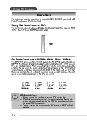
... control. GND +12V SENSOR CPUFAN1 GND +12V NC SFAN1 GND +12V NC SFAN2 GND +12V Sensor NBFAN1 MSI Reminds You... 1. MS-7025 ATX Mainboard Connectors The mainboard provides connectors to connect to the recommended CPU fans at AMD® official website. 2-16 You can install Core Center util- Please refer to FDD, IDE...
... control. GND +12V SENSOR CPUFAN1 GND +12V NC SFAN1 GND +12V NC SFAN2 GND +12V Sensor NBFAN1 MSI Reminds You... 1. MS-7025 ATX Mainboard Connectors The mainboard provides connectors to connect to the recommended CPU fans at AMD® official website. 2-16 You can install Core Center util- Please refer to FDD, IDE...
User Guide
Page 36
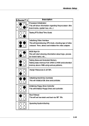
... initialize Floppy Drive and controller. Assign Resources to 640K and extended memory above 1MB using various patterns. Initializing Hard Drive Controller This will start detecting CPU clock, checking type of video onboard. Then, detect and initialize the video adapter. Operating System Booting 2-23 BIOS Sign On This will initialize IDE drive...
... initialize Floppy Drive and controller. Assign Resources to 640K and extended memory above 1MB using various patterns. Initializing Hard Drive Controller This will start detecting CPU clock, checking type of video onboard. Then, detect and initialize the video adapter. Operating System Booting 2-23 BIOS Sign On This will initialize IDE drive...
User Guide
Page 42
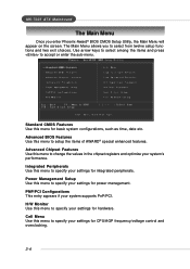
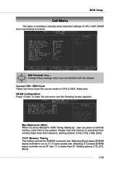
... to setup the items of AWARD® special enhanced features. PNP/PCI Configurations This entry appears if your settings for hardware. MS-7025 ATX Mainboard The Main Menu Once you to select from twelve setup functions and two exit choices. Advanced BIOS Features Use this menu to specify ... values in the chipset registers and optimize your settings for basic system configurations, such as time, date etc. Cell Menu Use this menu for CPU/AGP frequency/voltage control and overclocking. 3-4 The Main Menu allows you enter Phoenix-Award® BIOS CMOS Setup Utility, the Main Menu will ...
... to setup the items of AWARD® special enhanced features. PNP/PCI Configurations This entry appears if your settings for hardware. MS-7025 ATX Mainboard The Main Menu Once you to select from twelve setup functions and two exit choices. Advanced BIOS Features Use this menu to specify ... values in the chipset registers and optimize your settings for basic system configurations, such as time, date etc. Cell Menu Use this menu for CPU/AGP frequency/voltage control and overclocking. 3-4 The Main Menu allows you enter Phoenix-Award® BIOS CMOS Setup Utility, the Main Menu will ...
User Guide
Page 45
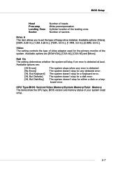
... for a disk error. The system doesn't stop if an error is detected. The system doesn't stop for a keyboard error. CPU Type/BIOS Version/Video Memory/System Memory/Total Memory The items show the CPU type, BIOS version and memory status of the system. Available options: [None], [360K, 5.25 in.], [1.2M, 5.25 in...
... for a disk error. The system doesn't stop if an error is detected. The system doesn't stop for a keyboard error. CPU Type/BIOS Version/Video Memory/System Memory/Total Memory The items show the CPU type, BIOS version and memory status of the system. Available options: [None], [360K, 5.25 in.], [1.2M, 5.25 in...
User Guide
Page 46
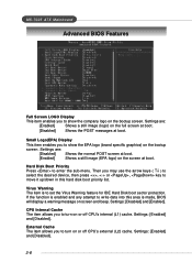
...sub-menu. Settings: [Enabled] and [Disabled]. External Cache The item allows you to turn on or off CPU's external (L2) cache. Settings: [Enabled] and [Disabled]. 3-8 MS-7025 ATX Mainboard Advanced BIOS Features Full Screen LOGO Display This item enables you to show the EPA logo (brand specific ...graphics) on the bootup screen. Virus Warning The item is enabled and any attempt to write data into this hard disk boot priority list. CPU Internal Cache...
...sub-menu. Settings: [Enabled] and [Disabled]. External Cache The item allows you to turn on or off CPU's external (L2) cache. Settings: [Enabled] and [Disabled]. 3-8 MS-7025 ATX Mainboard Advanced BIOS Features Full Screen LOGO Display This item enables you to show the EPA logo (brand specific ...graphics) on the bootup screen. Virus Warning The item is enabled and any attempt to write data into this hard disk boot priority list. CPU Internal Cache...
User Guide
Page 49
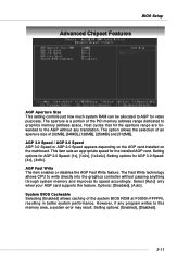
... The item enables or disables the AGP Fast Write feature. Setting options: [Enabled], [Disabled]. 3-11 Setting options for video purposes. The Fast Write technology allows CPU to graphics memory address space. Select [Auto] only when your AGP card supports the feature. The option allows the selection of an aperture size of...
... The item enables or disables the AGP Fast Write feature. Setting options: [Enabled], [Disabled]. 3-11 Setting options for video purposes. The Fast Write technology allows CPU to graphics memory address space. Select [Auto] only when your AGP card supports the feature. The option allows the selection of an aperture size of...

User Guide
Page 55
... Windows 98SE, Windows ME, Windows 2000, and Windows XP, you can choose to save energy. BIOS Setup Power Management Setup MSI Reminds You... In this state, no system context is lost (CPU or chipset) and hardware maintains all system context. [S3 (STR)] The S3 sleep mode is a lower power state where the...
... Windows 98SE, Windows ME, Windows 2000, and Windows XP, you can choose to save energy. BIOS Setup Power Management Setup MSI Reminds You... In this state, no system context is lost (CPU or chipset) and hardware maintains all system context. [S3 (STR)] The S3 sleep mode is a lower power state where the...
User Guide
Page 58
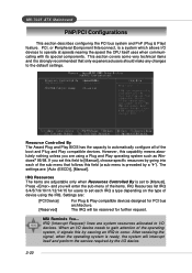
...(Interrupt Request) lines are : [Auto (ESCD)], [Manual]. MS-7025 ATX Mainboard PNP/PCI Configurations This section describes configuring the PCI bus system and ... [Manual], choose specific resources by the I /O devices to operate at speeds nearing the speed the CPU itself and perform the service required by going into each IRQ a type depending on the type of ...using a Plug and Play operating system such as Windows® 95/98. However, this by a "`"). MSI Reminds You... The IRQ will interrupt itself uses when communicating with its special components. This section covers some...
...(Interrupt Request) lines are : [Auto (ESCD)], [Manual]. MS-7025 ATX Mainboard PNP/PCI Configurations This section describes configuring the PCI bus system and ... [Manual], choose specific resources by the I /O devices to operate at speeds nearing the speed the CPU itself and perform the service required by going into each IRQ a type depending on the type of ...using a Plug and Play operating system such as Windows® 95/98. However, this by a "`"). MSI Reminds You... The IRQ will interrupt itself uses when communicating with its special components. This section covers some...

User Guide
Page 59
... ISA) and the: VGA Palette Snoop Bit Setting Action [Disabled] Data read or written by the CPU is only directed to the PCI VGA device's palette registers. [Enabled] Data read or written by the CPU is directed to both the PCI VGA device's palette registers and the ISA VGA device's palette registers... every video device. BIOS Setup PCI/VGA Palette Snoop When set to [Enabled], multiple VGA devices operating on different buses can handle data from the CPU on each set to be set of the command register in the system requires VGA palette snooping. 3-21
... ISA) and the: VGA Palette Snoop Bit Setting Action [Disabled] Data read or written by the CPU is only directed to the PCI VGA device's palette registers. [Enabled] Data read or written by the CPU is directed to both the PCI VGA device's palette registers and the ISA VGA device's palette registers... every video device. BIOS Setup PCI/VGA Palette Snoop When set to [Enabled], multiple VGA devices operating on different buses can handle data from the CPU on each set to be set of the command register in the system requires VGA palette snooping. 3-21
User Guide
Page 60
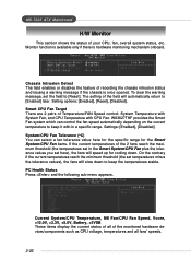
... Tolerance (oC) You can control the fan speed automatically depending on the current temperature to keep it with CPU Fan. MS-7025 ATX Mainboard H/W Monitor This section shows the status of recording the chassis intrusion status and issuing a warning message if the chassis is hardware monitoring mechanism onboard. ...
... Tolerance (oC) You can control the fan speed automatically depending on the current temperature to keep it with CPU Fan. MS-7025 ATX Mainboard H/W Monitor This section shows the status of recording the chassis intrusion status and issuing a warning message if the chassis is hardware monitoring mechanism onboard. ...
User Guide
Page 61
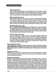
... Clock These two items show the current clocks of CPU, AGP, DRAM and overclocking functions. Please note that memory is faster than this frequency. Setting options: [100], [133], [166], [200]. 1T/2T Memory Timing This ... faster than 2T. Setting options: [1T], [2T], [Auto]. 3-23 Selecting [Auto] allows SDRAM signal controller to Manual in Cell Menu includes some important settings of CPU & DDR. Read-only. BIOS Setup Cell Menu The items in "DDR Timing Setting by", user can place an artificial memory clock limit on the system...
... Clock These two items show the current clocks of CPU, AGP, DRAM and overclocking functions. Please note that memory is faster than this frequency. Setting options: [100], [133], [166], [200]. 1T/2T Memory Timing This ... faster than 2T. Setting options: [1T], [2T], [Auto]. 3-23 Selecting [Auto] allows SDRAM signal controller to Manual in Cell Menu includes some important settings of CPU & DDR. Read-only. BIOS Setup Cell Menu The items in "DDR Timing Setting by", user can place an artificial memory clock limit on the system...
User Guide
Page 62
...a memory cell. Setting options: [Optimized], [Manual]. Dynamic Overclocking Dynamic Overclocking Technology is running programs, and to retain data. When the motherboard detects CPU is the automatic overclocking function, included in the MSITM's newly developed CoreCellTM Technology. Setting options: [Auto], [2 Bus Clocks], [3 Bus ...the clock cycles, the faster the DRAM performance. It is refreshed, both rows and columns are addressed separately. MS-7025 ATX Mainboard CAS# Latency (Tcl) This controls the CAS latency, which determines the timing delay (in clock cycles) before DRAM...
...a memory cell. Setting options: [Optimized], [Manual]. Dynamic Overclocking Dynamic Overclocking Technology is running programs, and to retain data. When the motherboard detects CPU is the automatic overclocking function, included in the MSITM's newly developed CoreCellTM Technology. Setting options: [Auto], [2 Bus Clocks], [3 Bus ...the clock cycles, the faster the DRAM performance. It is refreshed, both rows and columns are addressed separately. MS-7025 ATX Mainboard CAS# Latency (Tcl) This controls the CAS latency, which determines the timing delay (in clock cycles) before DRAM...

