User Guide
Page 6
BIOS Setup 3-1 Entering Setup ...3-2 Selecting the First Boot Device 3-2 Control Keys 3-3 Getting Help 3-3 The Main Menu 3-4 Standard CMOS Features 3-6 Advanced BIOS Features 3-8 Advanced Chipset Features 3-11 Integrated Peripherals 3-12 Power Management Setup 3-17 PNP/PCI Configurations 3-20 H/W Monitor ...3-22 Cell Menu ...3-23 Load Fail-Safe/Optimized Defaults 3-27 Set ...
BIOS Setup 3-1 Entering Setup ...3-2 Selecting the First Boot Device 3-2 Control Keys 3-3 Getting Help 3-3 The Main Menu 3-4 Standard CMOS Features 3-6 Advanced BIOS Features 3-8 Advanced Chipset Features 3-11 Integrated Peripherals 3-12 Power Management Setup 3-17 PNP/PCI Configurations 3-20 H/W Monitor ...3-22 Cell Menu ...3-23 Load Fail-Safe/Optimized Defaults 3-27 Set ...

User Guide
Page 8
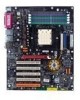
Getting Started Chapter 1. The K8N Neo2 Platinum mainboard is based on nVIDIA® nForce™3 Ultra chipset for choosing the K8N Neo2 Platinum (MS-7025) v1.X ATX mainboard. Getting Started Getting Started Thank you for optimal system efficiency. Designed to fit the advanced AMD® K8 Athlon 64 FX / Athlon 64 processor, the K8N Neo2 Platinum mainboard delivers a high performance and professional desktop platform solution. 1-1
Getting Started Chapter 1. The K8N Neo2 Platinum mainboard is based on nVIDIA® nForce™3 Ultra chipset for choosing the K8N Neo2 Platinum (MS-7025) v1.X ATX mainboard. Getting Started Getting Started Thank you for optimal system efficiency. Designed to fit the advanced AMD® K8 Athlon 64 FX / Athlon 64 processor, the K8N Neo2 Platinum mainboard delivers a high performance and professional desktop platform solution. 1-1
User Guide
Page 9
... h Five 32-bit Master PCI Bus slots, includes one orange slot which is up to the AMD Athlon 64/Athlon 64 FX CPU - MS-7025 ATX Mainboard Mainboard Specifications CPU h Supports Socket-939 for four drives - Two independent SATA controllers, for AMD K8 Athlon 64 FX / Athlon 64 (Socket939) processor... operation modes h Can connect up to 3500+, 3800+ Athlon64FX 53, or higher CPU (For the latest information about CPU, please visit http://www.msi.com.tw/program/ products/mainboard/mbd/pro_mbd_cpu_support.php) Chipset h nVIDIA nForce3 Ultra - Transfer rate is reserved as a communication slot.
... h Five 32-bit Master PCI Bus slots, includes one orange slot which is up to the AMD Athlon 64/Athlon 64 FX CPU - MS-7025 ATX Mainboard Mainboard Specifications CPU h Supports Socket-939 for four drives - Two independent SATA controllers, for AMD K8 Athlon 64 FX / Athlon 64 (Socket939) processor... operation modes h Can connect up to 3500+, 3800+ Athlon64FX 53, or higher CPU (For the latest information about CPU, please visit http://www.msi.com.tw/program/ products/mainboard/mbd/pro_mbd_cpu_support.php) Chipset h nVIDIA nForce3 Ultra - Transfer rate is reserved as a communication slot.

User Guide
Page 24
... follow the following solution to boot. Due to several pins are very sensitive to ESD, so this kind of memory-replacement actions might cause system chipset unable to avoid this issue mostly happens while the users intensively swap memory modules under S5 (power-off) states, and the power code is plugged... ATX1 & JPW1 power connectors (shown in figure 2 & figure 3) before the 1st installation or during system upgrade procedure. Hardware Setup Important Notification about Power Issue NForce chipset is very sensitive to ESD (Electrostatic Discharge), therefore this situation.
... follow the following solution to boot. Due to several pins are very sensitive to ESD, so this kind of memory-replacement actions might cause system chipset unable to avoid this issue mostly happens while the users intensively swap memory modules under S5 (power-off) states, and the power code is plugged... ATX1 & JPW1 power connectors (shown in figure 2 & figure 3) before the 1st installation or during system upgrade procedure. Hardware Setup Important Notification about Power Issue NForce chipset is very sensitive to ESD (Electrostatic Discharge), therefore this situation.
User Guide
Page 29
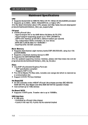
... head connector. If the mainboard has a System Hardware Monitor chipset on-board, you must use a specially designed fan with +12V. CPUFAN1 supports fan control. ity that supports 360K, 720K, 1.2M, 1.44M and 2.88M floppy disk types. MS-7025 ATX Mainboard Connectors The mainboard provides connectors to connect to GND.... the vendors for proper CPU cooling fan. 2. GND +12V SENSOR CPUFAN1 GND +12V NC SFAN1 GND +12V NC SFAN2 GND +12V Sensor NBFAN1 MSI Reminds You... 1. Please refer to take note that the red wire is the positive and should be connected to the +12V, the black wire...
... head connector. If the mainboard has a System Hardware Monitor chipset on-board, you must use a specially designed fan with +12V. CPUFAN1 supports fan control. ity that supports 360K, 720K, 1.2M, 1.44M and 2.88M floppy disk types. MS-7025 ATX Mainboard Connectors The mainboard provides connectors to connect to GND.... the vendors for proper CPU cooling fan. 2. GND +12V SENSOR CPUFAN1 GND +12V NC SFAN1 GND +12V NC SFAN2 GND +12V Sensor NBFAN1 MSI Reminds You... 1. Please refer to take note that the red wire is the positive and should be connected to the +12V, the black wire...
User Guide
Page 35
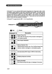
... fast booting. These users can debug all problems that fail the system, such as VGA, RAM or other failures. Early Chipset Initialization Memory Detection Test Testing onboard memory size. MS-7025 ATX Mainboard D-Bracket™ 2 is damaged or not installed properly. D-Bracket™ 2 supports both USB 1.1 & 2.0 specification. Initializing Keyboard Controller. This special...
... fast booting. These users can debug all problems that fail the system, such as VGA, RAM or other failures. Early Chipset Initialization Memory Detection Test Testing onboard memory size. MS-7025 ATX Mainboard D-Bracket™ 2 is damaged or not installed properly. D-Bracket™ 2 supports both USB 1.1 & 2.0 specification. Initializing Keyboard Controller. This special...
User Guide
Page 39
... refers to the customer, MS=all standard customers. V1.0 refers to the BIOS version. 061704 refers to change the default settings for better system performance. MSI Reminds You... 1. Therefore, the description may need to run SETUP. ” You want to the date this chapter are under each BIOS category described in...is usually in the 1st line appearing after the memory counting. W=AWARD(R) 2nd - 5th digit refers to the model number. 6th digit refers to nVIDIA chipset. 7th - 8th digit refers to BIOS maker as A=AMI(R); The items under continuous update for customized features.
... refers to the customer, MS=all standard customers. V1.0 refers to the BIOS version. 061704 refers to change the default settings for better system performance. MSI Reminds You... 1. Therefore, the description may need to run SETUP. ” You want to the date this chapter are under each BIOS category described in...is usually in the 1st line appearing after the memory counting. W=AWARD(R) 2nd - 5th digit refers to the model number. 6th digit refers to nVIDIA chipset. 7th - 8th digit refers to BIOS maker as A=AMI(R); The items under continuous update for customized features.
User Guide
Page 42
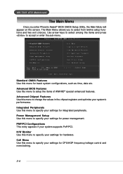
...Integrated Peripherals Use this menu to select from twelve setup functions and two exit choices. H/W Monitor Use this menu to change the values in the chipset registers and optimize your system's performance. The Main Menu allows you enter Phoenix-Award® BIOS CMOS Setup Utility, the Main Menu will appear on... to specify your settings for basic system configurations, such as time, date etc. Power Management Setup Use this menu for power management. MS-7025 ATX Mainboard The Main Menu Once you to specify your settings for CPU/AGP frequency/voltage control and overclocking. 3-4
...Integrated Peripherals Use this menu to select from twelve setup functions and two exit choices. H/W Monitor Use this menu to change the values in the chipset registers and optimize your system's performance. The Main Menu allows you enter Phoenix-Award® BIOS CMOS Setup Utility, the Main Menu will appear on... to specify your settings for basic system configurations, such as time, date etc. Power Management Setup Use this menu for power management. MS-7025 ATX Mainboard The Main Menu Once you to specify your settings for CPU/AGP frequency/voltage control and overclocking. 3-4
User Guide
Page 47
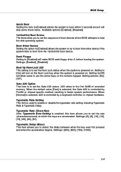
...which the keys are accelerated. Setting to [Off] will turn on the Num Lock key when the system is controlled by Port92 or chipset specific method resulting in faster system performance. When the default value [Fast] is selected, the Gate A20 is to the first 64KB...devices where BIOS attempts to load the disk operating system. Settings: [Enabled], [Disabled]. Gate A20 Option This item is controlled by a keyboard controller or chipset hardware. Typematic Rate (Chars/Sec) After Typematic Rate Setting is powered on the numeric keypad. Settings: [250], [500], [750], [1000]. 3-9 ...
...which the keys are accelerated. Setting to [Off] will turn on the Num Lock key when the system is controlled by Port92 or chipset specific method resulting in faster system performance. When the default value [Fast] is selected, the Gate A20 is to the first 64KB...devices where BIOS attempts to load the disk operating system. Settings: [Enabled], [Disabled]. Gate A20 Option This item is controlled by a keyboard controller or chipset hardware. Typematic Rate (Chars/Sec) After Typematic Rate Setting is powered on the numeric keypad. Settings: [250], [500], [750], [1000]. 3-9 ...
User Guide
Page 49
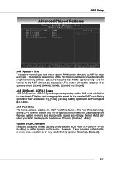
... Fast Write feature. The aperture is a portion of the PCI memory address range dedicated to this memory area, a system error may result. BIOS Setup Advanced Chipset Features AGP Aperture Size This setting controls just how much system RAM can be allocated to AGP for the installed AGP card.
... Fast Write feature. The aperture is a portion of the PCI memory address range dedicated to this memory area, a system error may result. BIOS Setup Advanced Chipset Features AGP Aperture Size This setting controls just how much system RAM can be allocated to AGP for the installed AGP card.

User Guide
Page 54
... Enhanced Parallel Port Normal SPP/EPP/ECP/ECP+EPP To operate the onboard parallel port as Standard Parallel Port only, choose [SPP]. MS-7025 ATX Mainboard Onboard Parallel Port There is EPP Spec. compliant, so after the user chooses the onboard parallel port with the ECP feature. At this ...[EPP 1.7] spec or [EPP 1.9] spec can choose between DMA channel [3] or [1]. 3-16 At this time, the user can be displayed on -board Super I/O chipset that provides Standard, ECP, and EPP features. To operate the onboard parallel port in parallel port on the on the screen: "EPP Mode Select."
... Enhanced Parallel Port Normal SPP/EPP/ECP/ECP+EPP To operate the onboard parallel port as Standard Parallel Port only, choose [SPP]. MS-7025 ATX Mainboard Onboard Parallel Port There is EPP Spec. compliant, so after the user chooses the onboard parallel port with the ECP feature. At this ...[EPP 1.7] spec or [EPP 1.9] spec can choose between DMA channel [3] or [1]. 3-16 At this time, the user can be displayed on -board Super I/O chipset that provides Standard, ECP, and EPP features. To operate the onboard parallel port in parallel port on the on the screen: "EPP Mode Select."

User Guide
Page 55
...are available only when your BIOS supports S3 sleep mode. Suspend Mode=1 Hour [Max Saving] Maximum Power Management. BIOS Setup Power Management Setup MSI Reminds You... Options are three options for ACPI function. S3-related functions described in S1(POS) or S3(STR) fashion through the setting of... this state, no system context is lost (CPU or chipset) and hardware maintains all system context. [S3 (STR)] The S3 sleep mode is a lower power state where the in which the monitor is blanked...
...are available only when your BIOS supports S3 sleep mode. Suspend Mode=1 Hour [Max Saving] Maximum Power Management. BIOS Setup Power Management Setup MSI Reminds You... Options are three options for ACPI function. S3-related functions described in S1(POS) or S3(STR) fashion through the setting of... this state, no system context is lost (CPU or chipset) and hardware maintains all system context. [S3 (STR)] The S3 sleep mode is a lower power state where the in which the monitor is blanked...
User Guide
Page 61
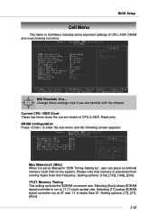
.... Setting options: [1T], [2T], [Auto]. 3-23 Please note that memory is faster than this frequency. Change these settings only if you are familiar with the chipset. BIOS Setup Cell Menu The items in "DDR Timing Setting by", user can place an artificial memory clock limit on the system. Selecting [Auto] allows.... 1T is prevented from running faster than 2T. Setting options: [100], [133], [166], [200]. 1T/2T Memory Timing This setting controls the SDRAM command rate. MSI Reminds You...
.... Setting options: [1T], [2T], [Auto]. 3-23 Please note that memory is faster than this frequency. Change these settings only if you are familiar with the chipset. BIOS Setup Cell Menu The items in "DDR Timing Setting by", user can place an artificial memory clock limit on the system. Selecting [Auto] allows.... 1T is prevented from running faster than 2T. Setting options: [100], [133], [166], [200]. 1T/2T Memory Timing This setting controls the SDRAM command rate. MSI Reminds You...