
User Manual
Page 13
... CPU_FAN1, PUMP_FAN1, SYS_FAN1~4: Fan Connectors 34 JAUD1: Front Audio Connector 35 JCI1: Chassis Intrusion Connector 35 JTPM1: TPM Module Connector 36 JBAT1: Clear CMOS (Reset BIOS) Jumper 36 JLPT1: Parallel Port Connector 37 Contents 13
... CPU_FAN1, PUMP_FAN1, SYS_FAN1~4: Fan Connectors 34 JAUD1: Front Audio Connector 35 JCI1: Chassis Intrusion Connector 35 JTPM1: TPM Module Connector 36 JBAT1: Clear CMOS (Reset BIOS) Jumper 36 JLPT1: Parallel Port Connector 37 Contents 13

User Manual
Page 14
EZ Debug LED...37 BIOS Setup ...38 Using BIOS ...39 Entering BIOS Setup 39 Resetting BIOS...40 Updating BIOS...40 EZ Mode ...41 Advanced Mode ...43 SETTINGS...44 Advanced...44 Boot...51 Security ...52 Save & Exit...53 OC...54 M-FLASH ...60 OC PROFILE ...61 ...
EZ Debug LED...37 BIOS Setup ...38 Using BIOS ...39 Entering BIOS Setup 39 Resetting BIOS...40 Updating BIOS...40 EZ Mode ...41 Advanced Mode ...43 SETTINGS...44 Advanced...44 Boot...51 Security ...52 Save & Exit...53 OC...54 M-FLASH ...60 OC PROFILE ...61 ...

User Manual
Page 18
... 1x 128 Mb/ 64 Mb flash (optional) y UEFI AMI BIOS y ACPI 5.0, PnP 1.0a, SM BIOS 2.8 y Multi-language y Drivers y COMMAND CENTER y LIVE UPDATE 6 y FAST BOOT y SUPER CHARGER y MYSTIC LIGHT y RAMDISK y X-BOOST y MSI SMART TOOL y NETWORK MANAGER y Intel® Extreme Tuning Utility ...y Norton™ Internet Security Solution y Google Chrome™ ,Google Toolbar, Google Drive y CLICK BIOS 5 (optional) ƒ EZ Mode & Advanced Mode Switching ƒ Board Explorer...
... 1x 128 Mb/ 64 Mb flash (optional) y UEFI AMI BIOS y ACPI 5.0, PnP 1.0a, SM BIOS 2.8 y Multi-language y Drivers y COMMAND CENTER y LIVE UPDATE 6 y FAST BOOT y SUPER CHARGER y MYSTIC LIGHT y RAMDISK y X-BOOST y MSI SMART TOOL y NETWORK MANAGER y Intel® Extreme Tuning Utility ...y Norton™ Internet Security Solution y Google Chrome™ ,Google Toolbar, Google Drive y CLICK BIOS 5 (optional) ƒ EZ Mode & Advanced Mode Switching ƒ Board Explorer...
User Manual
Page 20
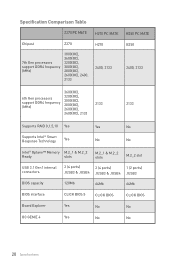
Specification Comparison Table Z270 PC MATE H270 PC MATE B250 PC MATE Chipest Z270 H270 7th Gen processors support DDR4 frequency (MHz) 3800(OC), 3600(OC), 3200(OC), 3000(OC), 2800(OC), 2600(OC), 2400, 2133 2400, 2133 B250 2400, ...® Optane™ Memory M.2_1 & M.2_2 Ready slots M.2_1 & M.2_2 slots M.2_2 slot USB 3.1 Gen1 internal connectors 2 (4 ports) 2 (4 ports) 1 (2 ports) JUSB3 & JUSB4 JUSB3 & JUSB4 JUSB3 BIOS capacity 128Mb 64Mb 64Mb BIOS interface CLICK BIOS 5 CLICK BIOS CLICK BIOS Board Explorer Yes No No OC GENIE 4 Yes No No 20 Specifications
Specification Comparison Table Z270 PC MATE H270 PC MATE B250 PC MATE Chipest Z270 H270 7th Gen processors support DDR4 frequency (MHz) 3800(OC), 3600(OC), 3200(OC), 3000(OC), 2800(OC), 2600(OC), 2400, 2133 2400, 2133 B250 2400, ...® Optane™ Memory M.2_1 & M.2_2 Ready slots M.2_1 & M.2_2 slots M.2_2 slot USB 3.1 Gen1 internal connectors 2 (4 ports) 2 (4 ports) 1 (2 ports) JUSB3 & JUSB4 JUSB3 & JUSB4 JUSB3 BIOS capacity 128Mb 64Mb 64Mb BIOS interface CLICK BIOS 5 CLICK BIOS CLICK BIOS Board Explorer Yes No No OC GENIE 4 Yes No No 20 Specifications

User Manual
Page 25
Component Contents Port Name CPU_FAN1, PUMP_FAN1, SYS_FAN1~4 CPU_PWR1, ATX_PWR1 JAUD1 JBAT1 JCI1 JCOM1 JFP1, JFP2 JLPT1 JTPM1 JUSB1~2 JUSB3, JUSB4(optional) M2_1~2 PCI_E1~5, PCI1 SATA1~6 Port Type Fan Connectors Power Connectors Front Audio Connector Clear CMOS (Reset BIOS) Jumper Chassis Intrusion Connector Serial Port Connector Front Panel Connectors Parallel Port Connector TPM Module Connector USB 2.0 Connectors USB 3.1 Gen1 Connectors M.2 Slots (Key M) PCIe/ PCI Expansion Slots SATA 6Gb/s Connectors Page 34 32 35 36 35 32 31 37 36 33 33 29 28 30 Overview of Components 25
Component Contents Port Name CPU_FAN1, PUMP_FAN1, SYS_FAN1~4 CPU_PWR1, ATX_PWR1 JAUD1 JBAT1 JCI1 JCOM1 JFP1, JFP2 JLPT1 JTPM1 JUSB1~2 JUSB3, JUSB4(optional) M2_1~2 PCI_E1~5, PCI1 SATA1~6 Port Type Fan Connectors Power Connectors Front Audio Connector Clear CMOS (Reset BIOS) Jumper Chassis Intrusion Connector Serial Port Connector Front Panel Connectors Parallel Port Connector TPM Module Connector USB 2.0 Connectors USB 3.1 Gen1 Connectors M.2 Slots (Key M) PCIe/ PCI Expansion Slots SATA 6Gb/s Connectors Page 34 32 35 36 35 32 31 37 36 33 33 29 28 30 Overview of Components 25

User Manual
Page 27
... B DIMMA2 Memory module installation recommendation DIMMB2 DIMMA2 DIMMB2 DIMMA2 DIMMB2 DIMMB1 DIMMA2 DIMMA1 Important y Always insert memory modules in the DIMMA2 slot first. y Due to BIOS and find the Memory Try It! to set the memory frequency if you want to operate the memory at the marked or at a lower frequency...
... B DIMMA2 Memory module installation recommendation DIMMB2 DIMMA2 DIMMB2 DIMMA2 DIMMB2 DIMMB1 DIMMA2 DIMMA1 Important y Always insert memory modules in the DIMMA2 slot first. y Due to BIOS and find the Memory Try It! to set the memory frequency if you want to operate the memory at the marked or at a lower frequency...

User Manual
Page 34
... PWM mode and DC mode and adjust fan speed in relation to adjust fan speed in BIOS > HARDWARE MONITOR. (The picture below shows the HARDWARE MONITOR screen for Z270 PC MATE, and that's different for H270 PC MATE and B250 PC MATE) Select PWM mode or DC mode There are working properly after switching the PWM/ DC mode...
... PWM mode and DC mode and adjust fan speed in relation to adjust fan speed in BIOS > HARDWARE MONITOR. (The picture below shows the HARDWARE MONITOR screen for Z270 PC MATE, and that's different for H270 PC MATE and B250 PC MATE) Select PWM mode or DC mode There are working properly after switching the PWM/ DC mode...

User Manual
Page 35
Resetting the chassis intrusion warning 1. Go to Enabled. 5. Connect the JCI1 connector to select Yes. Set Chassis Intrusion to BIOS > Settings > Security > Chassis Intrusion Configuration. 2. Set Chassis Intrusion to BIOS > Settings > Security > Chassis Intrusion Configuration. 4. Press F10 to save and exit and then press the Enter key to the chassis intrusion switch/ sensor...
Resetting the chassis intrusion warning 1. Go to Enabled. 5. Connect the JCI1 connector to select Yes. Set Chassis Intrusion to BIOS > Settings > Security > Chassis Intrusion Configuration. 2. Set Chassis Intrusion to BIOS > Settings > Security > Chassis Intrusion Configuration. 4. Press F10 to save and exit and then press the Enter key to the chassis intrusion switch/ sensor...

User Manual
Page 36
... Module). Use a jumper cap to clear the CMOS memory. Power off the computer and unplug the power cord 2. Keep Data (default) Clear CMOS/ Reset BIOS Resetting BIOS to the TPM security platform manual for more details and usages. 2 14 1 13 1 LPC Clock 2 3V Standby power 3 LPC Reset 4 3.3V Power...9 LPC address & data pin2 10 No Pin 11 LPC address & data pin3 12 Ground 13 LPC Frame 14 Ground JBAT1: Clear CMOS (Reset BIOS) Jumper There is CMOS memory onboard that is for about 5-10 seconds. 3. Plug the power cord and power on the motherboard to save system ...
... Module). Use a jumper cap to clear the CMOS memory. Power off the computer and unplug the power cord 2. Keep Data (default) Clear CMOS/ Reset BIOS Resetting BIOS to the TPM security platform manual for more details and usages. 2 14 1 13 1 LPC Clock 2 3V Standby power 3 LPC Reset 4 3.3V Power...9 LPC address & data pin2 10 No Pin 11 LPC address & data pin3 12 Ground 13 LPC Frame 14 Ground JBAT1: Clear CMOS (Reset BIOS) Jumper There is CMOS memory onboard that is for about 5-10 seconds. 3. Plug the power cord and power on the motherboard to save system ...
User Manual
Page 38
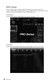
In this chapter we will use CLICK BIOS 5 to describe BIOS functions. CLICK BIOS 5 Z270 PC MATE provides CLICK BIOS 5 interface shown below . 38 BIOS Setup CLICK BIOS H270 PC MATE and B250 PC MATE provide CLICK BIOS interface shown below . However, BIOS functions are the same. BIOS Setup Z270 PC MATE, H270 PC MATE and B250 PC MATE provide different BIOS user interface CLICK BIOS 5 and CLICK BIOS.
In this chapter we will use CLICK BIOS 5 to describe BIOS functions. CLICK BIOS 5 Z270 PC MATE provides CLICK BIOS 5 interface shown below . 38 BIOS Setup CLICK BIOS H270 PC MATE and B250 PC MATE provide CLICK BIOS interface shown below . However, BIOS functions are the same. BIOS Setup Z270 PC MATE, H270 PC MATE and B250 PC MATE provide different BIOS user interface CLICK BIOS 5 and CLICK BIOS.

User Manual
Page 39
... Menu message appears on GO2BIOS button and choose OK. y The pictures in normal conditions. y Use MSI FAST BOOT application. The system will reboot and enter BIOS setup directly. BIOS Setup 39 Important y BIOS items are familiar with BIOS. Entering BIOS Setup Please refer the following methods to confirm your choice. Select between Advanced mode and EZ...
... Menu message appears on GO2BIOS button and choose OK. y The pictures in normal conditions. y Use MSI FAST BOOT application. The system will reboot and enter BIOS setup directly. BIOS Setup 39 Important y BIOS items are familiar with BIOS. Entering BIOS Setup Please refer the following methods to confirm your choice. Select between Advanced mode and EZ...
User Manual
Page 40
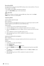
... update file into the USB flash drive. And then click Next and Start to download and install the latest BIOS file. 5. Insert the USB flash drive that matches your motherboard model from MSI website. Click Next and choose In Windows mode. Important Be sure the computer is 100% completed, the system will...
... update file into the USB flash drive. And then click Next and Start to download and install the latest BIOS file. 5. Insert the USB flash drive that matches your motherboard model from MSI website. Click Next and choose In Windows mode. Important Be sure the computer is 100% completed, the system will...

User Manual
Page 41
...for OC. y Setup Mode switch - y System information - shows the CPU/ DDR speed, CPU/ MB temperature, MB/ CPU type, memory size, CPU/ DDR voltage, BIOS version and build date. The boot priority from high to low is installed. Switch the outer circle to exit search page. profile. y Screenshot - Move the... and allows you to search by pressing the Setup Mode switch or F7 function key. BIOS Setup 41 you to configure the basic setting. It allows you to select the language of BIOS setup. click on this tab or the Ctrl+F keys and the search page will only...
...for OC. y Setup Mode switch - y System information - shows the CPU/ DDR speed, CPU/ MB temperature, MB/ CPU type, memory size, CPU/ DDR voltage, BIOS version and build date. The boot priority from high to low is installed. Switch the outer circle to exit search page. profile. y Screenshot - Move the... and allows you to search by pressing the Setup Mode switch or F7 function key. BIOS Setup 41 you to configure the basic setting. It allows you to select the language of BIOS setup. click on this tab or the Ctrl+F keys and the search page will only...
User Manual
Page 42
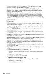
... Please note that includes RAID driver. y You can save and access favorite/ frequently-used / favorite BIOS setting items in RAID 0 automatically. It allows you to create personal BIOS menu where you can use MSI SMART TOOL to build the Windows® 7/ 8.1/ 10 installation drive that you can start to build ... setup, the RAID driver may be required and you must install M.2 SSDs of the same model and type in MSI Driver Disc. Move the mouse over a BIOS item not only on BIOS menu but also on favorite page (Favorite 1~5) 2. y If your system currently boots to M.2 SSD RAID and ...
... Please note that includes RAID driver. y You can save and access favorite/ frequently-used / favorite BIOS setting items in RAID 0 automatically. It allows you to create personal BIOS menu where you can use MSI SMART TOOL to build the Windows® 7/ 8.1/ 10 installation drive that you can start to build ... setup, the RAID driver may be required and you must install M.2 SSDs of the same model and type in MSI Driver Disc. Move the mouse over a BIOS item not only on BIOS menu but also on favorite page (Favorite 1~5) 2. y If your system currently boots to M.2 SSD RAID and ...

User Manual
Page 43
... 43 XMP switch Setup Mode switch OC GENIE 4 switch Screenshot Search Language System information Boot device priority bar BIOS menu selection BIOS menu selection Menu display y OC GENIE 4 switch/ XMP switch/ Setup Mode switch/ Screenshot/ Favorites/ Language/ System information/ Boot device priority bar - ... this motherboard. Advanced Mode Press Setup Mode switch or F7 function key can switch between EZ Mode and Advanced Mode in BIOS setup. allows you to adjust the frequency and voltage. allows you to manage overclocking profiles. ƒ HARDWARE MONITOR - provides...
... 43 XMP switch Setup Mode switch OC GENIE 4 switch Screenshot Search Language System information Boot device priority bar BIOS menu selection BIOS menu selection Menu display y OC GENIE 4 switch/ XMP switch/ Setup Mode switch/ Screenshot/ Favorites/ Language/ System information/ Boot device priority bar - ... this motherboard. Advanced Mode Press Setup Mode switch or F7 function key can switch between EZ Mode and Advanced Mode in BIOS setup. allows you to adjust the frequency and voltage. allows you to manage overclocking profiles. ƒ HARDWARE MONITOR - provides...

User Manual
Page 44
...from 1 to 31 can be keyed by numeric function keys. Use tab key to enter the sub-menu. 44 BIOS Setup The year can be adjusted by BIOS. Use tab key to Sat, determined by users. Day of the week, from Sun to switch between time ...cable connections of connected SATA device. The format is . The date from Jan. f System Information Shows detailed system information, including CPU type, BIOS version, and Memory (read only). Advanced f PCI Subsystem Settings Sets PCI, PCI express interface protocol and latency timer. SETTINGS System Status f System...
...from 1 to 31 can be keyed by numeric function keys. Use tab key to enter the sub-menu. 44 BIOS Setup The year can be adjusted by BIOS. Use tab key to Sat, determined by users. Day of the week, from Sun to switch between time ...cable connections of connected SATA device. The format is . The date from Jan. f System Information Shows detailed system information, including CPU type, BIOS version, and Memory (read only). Advanced f PCI Subsystem Settings Sets PCI, PCI express interface protocol and latency timer. SETTINGS System Status f System...
User Manual
Page 45
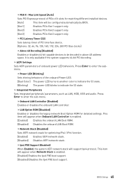
...detailed settings. fOnboard LAN Controller [Enabled] Enables or disables the onboard LAN controller. This item will be decoded in above 4G address space. BIOS Setup 45 Max Link Speed [Auto] Sets PCI Express protocol of the onboard Power LED. [Dual Color] The power LED turns to ...another color to indicate the S3 state. [Blinking] The power LED blinks to be configured automatically by BIOS. [Gen1] Enables PCIe Gen1 support only. [Gen2] Enables PCIe Gen2 support only. [Gen3] Enables PCIe Gen3 support only. f ACPI Settings Sets ...
...detailed settings. fOnboard LAN Controller [Enabled] Enables or disables the onboard LAN controller. This item will be decoded in above 4G address space. BIOS Setup 45 Max Link Speed [Auto] Sets PCI Express protocol of the onboard Power LED. [Dual Color] The power LED turns to ...another color to indicate the S3 state. [Blinking] The power LED blinks to be configured automatically by BIOS. [Gen1] Enables PCIe Gen1 support only. [Gen2] Enables PCIe Gen2 support only. [Gen3] Enables PCIe Gen3 support only. f ACPI Settings Sets ...

User Manual
Page 46
... as Native Command Queuing (NCQ) and hot-plugging. [RAID Mode] Enables RAID function for both integrated and external graphics cards. [Disabled] Disables this function. 46 BIOS Setup This item will appear when IGD Multi-Monitor is enabled. [Enabled] Enables the Ipv6 PXE boot support. [Disabled] Disables the Ipv6 PXE boot support...
... as Native Command Queuing (NCQ) and hot-plugging. [RAID Mode] Enables RAID function for both integrated and external graphics cards. [Disabled] Disables this function. 46 BIOS Setup This item will appear when IGD Multi-Monitor is enabled. [Enabled] Enables the Ipv6 PXE boot support. [Disabled] Disables the Ipv6 PXE boot support...

User Manual
Page 47
...hand-off feature. fUSB Speed Optimization [Auto] Enables or Disables the USB speed optimization. BIOS Setup 47 fUSB Controller [Enabled] Enables or disables all USB controller. If set to Auto, BIOS will be unavailable under legacy mode. f Super IO Configuration Sets system Super ...Port [Enabled] Enables or disables parallel(LPT) port. fParallel (LPT) Port Settings [Auto] Sets parallel port (LPT). If set to Auto, BIOS will optimize the IRQ automatically or you can set it manually. fLegacy USB Support [Enabled] Sets Legacy USB function support. [Auto] The system ...
...hand-off feature. fUSB Speed Optimization [Auto] Enables or Disables the USB speed optimization. BIOS Setup 47 fUSB Controller [Enabled] Enables or disables all USB controller. If set to Auto, BIOS will be unavailable under legacy mode. f Super IO Configuration Sets system Super ...Port [Enabled] Enables or disables parallel(LPT) port. fParallel (LPT) Port Settings [Auto] Sets parallel port (LPT). If set to Auto, BIOS will optimize the IRQ automatically or you can set it manually. fLegacy USB Support [Enabled] Sets Legacy USB function support. [Auto] The system ...

User Manual
Page 48
... other operating systems. Before enabling this item, make sure all installed devices & utilities (hardware & software) should meet the Windows equirement. [Disabled] Disables this function. 48 BIOS Setup fSystem Power Fault Protection [Disabled] Enables or disables the system to boot up the system after restoring AC power. [Power On] Boot up when...
... other operating systems. Before enabling this item, make sure all installed devices & utilities (hardware & software) should meet the Windows equirement. [Disabled] Disables this function. 48 BIOS Setup fSystem Power Fault Protection [Disabled] Enables or disables the system to boot up the system after restoring AC power. [Power On] Boot up when...


