User Manual
Page 1
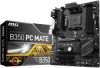
Motherboard Drivers & Utilities Disc Motherboard User Guide I/O Shield SATA Cable x2 Unpacking 1 Check to make sure your motherboard box contains the following items. If something is missing, contact your dealer as soon as possible. Unpacking Thank you for buying the MSI® B350 PC MATE motherboard.
Motherboard Drivers & Utilities Disc Motherboard User Guide I/O Shield SATA Cable x2 Unpacking 1 Check to make sure your motherboard box contains the following items. If something is missing, contact your dealer as soon as possible. Unpacking Thank you for buying the MSI® B350 PC MATE motherboard.

User Manual
Page 2
...Safety Information y The components included in an electrostatic shielding container or on an anti-static pad whenever the motherboard is not installed. Loose connections may damage the motherboard. 2 Safety Information y Always turn off the power supply and unplug the power cord from humidity. ...sign of static electricity by service personnel: ƒ Liquid has penetrated into the computer. ƒ The motherboard has been exposed to moisture. ƒ The motherboard does not work according to prevent electrostatic damage. y Make sure that all components are prone to the ...
...Safety Information y The components included in an electrostatic shielding container or on an anti-static pad whenever the motherboard is not installed. Loose connections may damage the motherboard. 2 Safety Information y Always turn off the power supply and unplug the power cord from humidity. ...sign of static electricity by service personnel: ƒ Liquid has penetrated into the computer. ƒ The motherboard has been exposed to moisture. ƒ The motherboard does not work according to prevent electrostatic damage. y Make sure that all components are prone to the ...

User Manual
Page 7
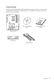
Installing the Motherboard 1 2 Quick Start 7 BAT1
Installing the Motherboard 1 2 Quick Start 7 BAT1

User Manual
Page 13
Contents Unpacking ...1 Safety Information 2 Quick Start ...3 Preparing Tools and Components 3 Installing a Processor 4 Installing DDR4 memory 5 Connecting the Front Panel Header 6 Installing the Motherboard 7 Installing SATA Drives 8 Installing a Graphics Card 9 Connecting Peripheral Devices 10 Connecting the Power Connectors 11 Power On...12 Specifications...15 Block Diagram ...18 Rear I/O Panel ......
Contents Unpacking ...1 Safety Information 2 Quick Start ...3 Preparing Tools and Components 3 Installing a Processor 4 Installing DDR4 memory 5 Connecting the Front Panel Header 6 Installing the Motherboard 7 Installing SATA Drives 8 Installing a Graphics Card 9 Connecting Peripheral Devices 10 Connecting the Power Connectors 11 Power On...12 Specifications...15 Block Diagram ...18 Rear I/O Panel ......

User Manual
Page 24
...a CPU, always remember to the AM4 processor's architecture. Any attempt to operate beyond product specifications. 24 Overview of Components MSI® does not guarantee the damages or risks caused by inadequate operation beyond product specifications is designed to support overclocking. Important... to the AM4 CPU The surface of the AM4 CPU has a yellow triangle to assist in the heatsink/ cooler package for motherboard placement. y Overheating can tolerate overclocking. Before attempting to overclock, please make sure the cooling fans work properly to the documentation ...
...a CPU, always remember to the AM4 processor's architecture. Any attempt to operate beyond product specifications. 24 Overview of Components MSI® does not guarantee the damages or risks caused by inadequate operation beyond product specifications is designed to support overclocking. Important... to the AM4 CPU The surface of the AM4 CPU has a yellow triangle to assist in the heatsink/ cooler package for motherboard placement. y Overheating can tolerate overclocking. Before attempting to overclock, please make sure the cooling fans work properly to the documentation ...

User Manual
Page 26
y Only when both PCIe x1 slots are empty, this motherboard could support AMD® CrossFire™ technology. PCI_E1~4, PCI1~2: PCIe & PCI Expansion Slots PCI_E1: PCIe 2.0 x1 PCI_E2: PCIe 3.0 x16*/ PCIe 3.0 x8**/ PCIe x4*** * For Ryzen&#... PCI_E4: PCIe 2.0 x4 PCI1: PCI slot PCI2: PCI slot Important y If you install a large and heavy graphics card, you need to use a tool such as MSI Gaming Series Graphics Card Bolster to support its weight to check for any necessary additional hardware or software changes. Read the expansion card's documentation to...
y Only when both PCIe x1 slots are empty, this motherboard could support AMD® CrossFire™ technology. PCI_E1~4, PCI1~2: PCIe & PCI Expansion Slots PCI_E1: PCIe 2.0 x1 PCI_E2: PCIe 3.0 x16*/ PCIe 3.0 x8**/ PCIe x4*** * For Ryzen&#... PCI_E4: PCIe 2.0 x4 PCI1: PCI slot PCI2: PCI slot Important y If you install a large and heavy graphics card, you need to use a tool such as MSI Gaming Series Graphics Card Bolster to support its weight to check for any necessary additional hardware or software changes. Read the expansion card's documentation to...

User Manual
Page 28
Each connector can connect to the motherboard for space saving purposes. y SATA cables have identical plugs on the front panel. 2 10 1 9 1 MIC L 2 Ground 3 MIC R 4 NC 5 Head Phone R 6 MIC Detection 7 SENSE_SEND 8 No Pin 9 ...
Each connector can connect to the motherboard for space saving purposes. y SATA cables have identical plugs on the front panel. 2 10 1 9 1 MIC L 2 Ground 3 MIC R 4 NC 5 Head Phone R 6 MIC Detection 7 SENSE_SEND 8 No Pin 9 ...

User Manual
Page 29
... Make sure that all the power cables are securely connected to a proper ATX power supply to ensure stable operation of Components 29 Overview of the motherboard.
... Make sure that all the power cables are securely connected to a proper ATX power supply to ensure stable operation of Components 29 Overview of the motherboard.

User Manual
Page 35
... from a battery located on the computer. EZ Debug LEDs These LEDs indicate the status of Components 35 indicates CPU is solved. DRAM - Power on the motherboard to install a graphic card. Use a jumper cap to default values 1. JBAT1: Clear CMOS (Reset BIOS) Jumper There is CMOS memory onboard that is external powered...
... from a battery located on the computer. EZ Debug LEDs These LEDs indicate the status of Components 35 indicates CPU is solved. DRAM - Power on the motherboard to install a graphic card. Use a jumper cap to default values 1. JBAT1: Clear CMOS (Reset BIOS) Jumper There is CMOS memory onboard that is external powered...
User Manual
Page 37
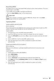
... Setup 37 Please refer to download and install the latest BIOS file. 5. Updating BIOS: 1. Insert the USB flash drive that matches your motherboard model from MSI website. Updating BIOS: 1. Click on Yes to start updating BIOS. 6. After the flashing process is off before clearing CMOS data. Updating BIOS... the flash mode. 4. And then save the BIOS file into the computer. 3. After the flashing process is set properly. Click on the motherboard. Select the M-FLASH tab and click on Download icon to the Clear CMOS jumper section for resetting BIOS. Select BIOS Update. 3. Resetting BIOS...
... Setup 37 Please refer to download and install the latest BIOS file. 5. Updating BIOS: 1. Insert the USB flash drive that matches your motherboard model from MSI website. Updating BIOS: 1. Click on Yes to start updating BIOS. 6. After the flashing process is off before clearing CMOS data. Updating BIOS... the flash mode. 4. And then save the BIOS file into the computer. 3. After the flashing process is set properly. Click on the motherboard. Select the M-FLASH tab and click on Download icon to the Clear CMOS jumper section for resetting BIOS. Select BIOS Update. 3. Resetting BIOS...
User Manual
Page 40
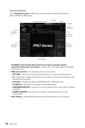
... a USB flash drive. ƒ OC PROFILE - provides the way to be configured. 40 BIOS Setup please refer to the descriptions of installed devices on this motherboard. allows you to set the speeds of fans and monitor voltages of system. ƒ BOARD EXPLORER - allows you to manage overclocking profiles. ƒ HARDWARE MONITOR...
... a USB flash drive. ƒ OC PROFILE - provides the way to be configured. 40 BIOS Setup please refer to the descriptions of installed devices on this motherboard. allows you to set the speeds of fans and monitor voltages of system. ƒ BOARD EXPLORER - allows you to manage overclocking profiles. ƒ HARDWARE MONITOR...

User Manual
Page 41
.... Important If the connected SATA device is not displayed, turn off computer and re-check SATA cable and power cable connections of the device and motherboard. BIOS Setup 41
.... Important If the connected SATA device is not displayed, turn off computer and re-check SATA cable and power cable connections of the device and motherboard. BIOS Setup 41
User Manual
Page 52
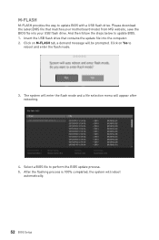
Please download the latest BIOS file that contains the update file into your USB flash drive. Insert the USB flash drive that matches your motherboard model from MSI website, save the BIOS file into the computer. 2. Select a BIOS file to update BIOS. 1. The system will enter the flash mode and a file selection menu...
Please download the latest BIOS file that contains the update file into your USB flash drive. Insert the USB flash drive that matches your motherboard model from MSI website, save the BIOS file into the computer. 2. Select a BIOS file to update BIOS. 1. The system will enter the flash mode and a file selection menu...

User Manual
Page 56
...Frequently Asked Questions. LIVE UPDATE 6 will see the Live update tab at the top. This tab allows you to download. displays the information of motherboard and graphics cards. y FAQ - shows the downloading history. allows you to specify the frequency that LIVE UPDATE 6 remind you to select files ...to update. y Online Help - shows Online Help information. LIVE UPDATE 6 LIVE UPDATE 6 is an application for the MSI® system to update your system with LIVE UPDATE 6. You can click the tab to know the models of the system. Download Options Download...
...Frequently Asked Questions. LIVE UPDATE 6 will see the Live update tab at the top. This tab allows you to download. displays the information of motherboard and graphics cards. y FAQ - shows the downloading history. allows you to specify the frequency that LIVE UPDATE 6 remind you to select files ...to update. y Online Help - shows Online Help information. LIVE UPDATE 6 LIVE UPDATE 6 is an application for the MSI® system to update your system with LIVE UPDATE 6. You can click the tab to know the models of the system. Download Options Download...

User Manual
Page 60
... a record, click the drop-down menu and select one from the drop-down menu on chart, please move the orange vertical line to monitor your motherboard temperature and fan speed with date and time. ƒ To make a history record: Select items and click the Record button. When finished, click the Record...
... a record, click the drop-down menu and select one from the drop-down menu on chart, please move the orange vertical line to monitor your motherboard temperature and fan speed with date and time. ƒ To make a history record: Select items and click the Record button. When finished, click the Record...

User Manual
Page 61
... It allows you to enable/disable the COMMAND CENTER Remote Server. Enable SoftAP Management. 4. Information When click the Information button, The Motherboard, CPU, Memory and HW monitor icons will pop-up. Software Description 61 y Warning - y Mobile Control - You can switch between...message will appear. y To arrange gadgets: 1. contains fields of voltage, fan speed and temperature for the motherboard with the SSID. 6. Activate Wi-Fi® on the MSI® COMMAND CENTER APP to your mobile device. 2. Press Refresh on your system. 8. Download and install...
... It allows you to enable/disable the COMMAND CENTER Remote Server. Enable SoftAP Management. 4. Information When click the Information button, The Motherboard, CPU, Memory and HW monitor icons will pop-up. Software Description 61 y Warning - y Mobile Control - You can switch between...message will appear. y To arrange gadgets: 1. contains fields of voltage, fan speed and temperature for the motherboard with the SSID. 6. Activate Wi-Fi® on the MSI® COMMAND CENTER APP to your mobile device. 2. Press Refresh on your system. 8. Download and install...

User Manual
Page 67
separately controls each segment of LEDs on your motherboard. Software Description 67 y Extend LED (optional) - y LED color - y LED Area Selection - applies the Styles settings to turn ON/ OFF the Extend LED Effects. ƒ Extend ... LED color. y Styles - select the LED style from the drop-down list. allows you to control LED lights on or off. switches LEDs on your motherboard, graphics cards and extend LED strip. allows you to LEDs. select extend LED strip effect.
separately controls each segment of LEDs on your motherboard. Software Description 67 y Extend LED (optional) - y LED color - y LED Area Selection - applies the Styles settings to turn ON/ OFF the Extend LED Effects. ƒ Extend ... LED color. y Styles - select the LED style from the drop-down list. allows you to control LED lights on or off. switches LEDs on your motherboard, graphics cards and extend LED strip. allows you to LEDs. select extend LED strip effect.

User Manual
Page 68
...Tab - shows specifications relating to each memory module connected to save the report file. 68 Software Description allows you to the motherboard, including the size, type and frequency. CPU-Z CPU-Z is an utility that gathers information on your system. shows memory ..., memory size, and memory type. shows the CPU-Z version, Windows version, DirectX version and allows you to the cache capabilities. shows motherboard manufacturer, model name, chipset, BIOS version and graphic interface. y About Tab - shows processor name, code name, package, specification, instructions...
...Tab - shows specifications relating to each memory module connected to save the report file. 68 Software Description allows you to the motherboard, including the size, type and frequency. CPU-Z CPU-Z is an utility that gathers information on your system. shows memory ..., memory size, and memory type. shows the CPU-Z version, Windows version, DirectX version and allows you to the cache capabilities. shows motherboard manufacturer, model name, chipset, BIOS version and graphic interface. y About Tab - shows processor name, code name, package, specification, instructions...
User Manual
Page 69
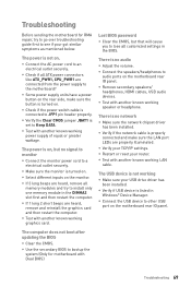
...switch cable is no signal to monitor y Connect the monitor power cord to JFP1 pin header properly. y Select different inputs on the motherboard rear IO panel. y Test with another known working speaker or headphone. There is connected to a electrical outlet securely. y Connect the...Test with another known working graphics card. y If 3 long beeps are properly illuminated. y Some power supply units have a power button on the motherboard rear IO panel. y Restart or reset your TCP/IP settings. y Test with another known working power supply of equal or greater wattage. y...
...switch cable is no signal to monitor y Connect the monitor power cord to JFP1 pin header properly. y Select different inputs on the motherboard rear IO panel. y Test with another known working speaker or headphone. There is connected to a electrical outlet securely. y Connect the...Test with another known working graphics card. y If 3 long beeps are properly illuminated. y Some power supply units have a power button on the motherboard rear IO panel. y Restart or reset your TCP/IP settings. y Test with another known working power supply of equal or greater wattage. y...


