User Manual
Page 1
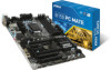
Check to make sure your motherboard box contains the following items. If something is missing, contact your dealer as soon as possible. Motherboard Drivers & Utilities Disc Motherboard User Guide I/O Shield SATA Cable x2 Unpacking 1 Unpacking Thank you for buying the MSI® H170A PC MATE/ B150 PC MATE motherboard.
Check to make sure your motherboard box contains the following items. If something is missing, contact your dealer as soon as possible. Motherboard Drivers & Utilities Disc Motherboard User Guide I/O Shield SATA Cable x2 Unpacking 1 Unpacking Thank you for buying the MSI® H170A PC MATE/ B150 PC MATE motherboard.

User Manual
Page 2
...power outlet before installing or removing any computer component. ●● Keep this user guide for future reference. ●● Keep this motherboard away from electrostatic discharge (ESD). Do not place anything over the power cord. ●● All cautions and warnings on it may ...cause the computer to not recognize a component or fail to start. ●● Hold the motherboard by the edges to avoid touching sensitive components. ●● It is not available, discharge yourself of the following instructions to prevent electrostatic ...
...power outlet before installing or removing any computer component. ●● Keep this user guide for future reference. ●● Keep this motherboard away from electrostatic discharge (ESD). Do not place anything over the power cord. ●● All cautions and warnings on it may ...cause the computer to not recognize a component or fail to start. ●● Hold the motherboard by the edges to avoid touching sensitive components. ●● It is not available, discharge yourself of the following instructions to prevent electrostatic ...

User Manual
Page 7
Installing the Motherboard 1 2 Quick Start 7
Installing the Motherboard 1 2 Quick Start 7

User Manual
Page 13
Contents Unpacking...1 Safety Information...2 Quick Start...3 Preparing Tools and Components 3 Installing a Processor 4 Installing DDR4 memory 5 Connecting the Front Panel Header 6 Installing the Motherboard 7 Installing SATA Drives 8 Installing a Graphics Card 9 Connecting Peripheral Devices 10 Connecting the Power Connectors 11 Power On...12 Specifications...15 Block Diagram ...19 Rear I/O Panel......
Contents Unpacking...1 Safety Information...2 Quick Start...3 Preparing Tools and Components 3 Installing a Processor 4 Installing DDR4 memory 5 Connecting the Front Panel Header 6 Installing the Motherboard 7 Installing SATA Drives 8 Installing a Graphics Card 9 Connecting Peripheral Devices 10 Connecting the Power Connectors 11 Power On...12 Specifications...15 Block Diagram ...19 Rear I/O Panel......

User Manual
Page 24
...CPU The surface of the LGA 1151 CPU has two notches and a golden triangle to assist in the heatsink/ cooler package for motherboard placement. Important ●● Always unplug the power cord from overheating. A CPU heatsink is not installed, always protect the ...system components can seriously damage the CPU and motherboard. Before attempting to overclock, please make sure the cooling fans work properly to install a CPU heatsink. MSI will deal with Return Merchandise Authorization (RMA) requests if only the motherboard comes with the CPU before installing or removing ...
...CPU The surface of the LGA 1151 CPU has two notches and a golden triangle to assist in the heatsink/ cooler package for motherboard placement. Important ●● Always unplug the power cord from overheating. A CPU heatsink is not installed, always protect the ...system components can seriously damage the CPU and motherboard. Before attempting to overclock, please make sure the cooling fans work properly to install a CPU heatsink. MSI will deal with Return Merchandise Authorization (RMA) requests if only the motherboard comes with the CPU before installing or removing ...

User Manual
Page 25
... Serial Presence Detect (SPD). ●● It is 4GB or less for 32-bit Windows OS due to use a more than 4GB memory on the motherboard. ●● Some memory may operate at a lower frequency than the marked value when overclocking due to the memory frequency operates dependent on installed CPU...
... Serial Presence Detect (SPD). ●● It is 4GB or less for 32-bit Windows OS due to use a more than 4GB memory on the motherboard. ●● Some memory may operate at a lower frequency than the marked value when overclocking due to the memory frequency operates dependent on installed CPU...

User Manual
Page 27
Each SATAe connector can connect to the motherboard for space saving purposes. Data loss may result during transmission otherwise. ●● SATA cable has identical plugs on either sides of Components 27 SATA1 ...
Each SATAe connector can connect to the motherboard for space saving purposes. Data loss may result during transmission otherwise. ●● SATA cable has identical plugs on either sides of Components 27 SATA1 ...

User Manual
Page 30
... +5V +5V Ground Important Make sure that all the power cables are securely connected to a proper ATX power supply to ensure stable operation of the motherboard. 30 Overview of Components
... +5V +5V Ground Important Make sure that all the power cables are securely connected to a proper ATX power supply to ensure stable operation of the motherboard. 30 Overview of Components
User Manual
Page 34
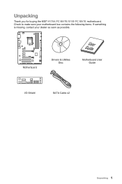
... system configuration data. Remove the jumper cap from a battery located on the computer. 34 Overview of Components Plug the power cord and power on the motherboard to connect the optional parallel port with bracket. 2 26 1 25 1 RSTB# 2 AFD# 3 PRND0 4 ERR# 5 PRND1 6 PINIT# 7 PRND2 8 LPT_SLIN# 9 PRND3 10 Ground 11 PRND4 12 Ground...
... system configuration data. Remove the jumper cap from a battery located on the computer. 34 Overview of Components Plug the power cord and power on the motherboard to connect the optional parallel port with bracket. 2 26 1 25 1 RSTB# 2 AFD# 3 PRND0 4 ERR# 5 PRND1 6 PINIT# 7 PRND2 8 LPT_SLIN# 9 PRND3 10 Ground 11 PRND4 12 Ground...
User Manual
Page 35
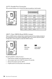
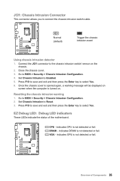
... not detected or fail. Normal (default) Trigger the chassis intrusion event Using chassis intrusion detector 1. indicates DRAM is not detected or fail. Overview of the motherboard. Connect the JCI1 connector to Reset. 3. Close the chassis cover. 3. EZ Debug LED: Debug LED indicators These LEDs indicate the status of Components 35 VGA...
... not detected or fail. Normal (default) Trigger the chassis intrusion event Using chassis intrusion detector 1. indicates DRAM is not detected or fail. Overview of the motherboard. Connect the JCI1 connector to Reset. 3. Close the chassis cover. 3. EZ Debug LED: Debug LED indicators These LEDs indicate the status of Components 35 VGA...
User Manual
Page 37
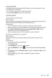
Insert the USB flash drive that matches your motherboard model from MSI website. Updating the BIOS with M-FLASH Before updating: Please download the latest BIOS file that contains the update file into the USB flash drive. Check ... BIOS Setup during POST. 3. Reboot the system, and then press Del key to load optimized defaults. ●● Short the Clear CMOS jumper on the motherboard. Go to BIOS > M-FLASH > Select one file to update BIOS and ME, select a BIOS file to download and install the latest BIOS 5. Select the MB...
Insert the USB flash drive that matches your motherboard model from MSI website. Updating the BIOS with M-FLASH Before updating: Please download the latest BIOS file that contains the update file into the USB flash drive. Check ... BIOS Setup during POST. 3. Reboot the system, and then press Del key to load optimized defaults. ●● Short the Clear CMOS jumper on the motherboard. Go to BIOS > M-FLASH > Select one file to update BIOS and ME, select a BIOS file to download and install the latest BIOS 5. Select the MB...

User Manual
Page 38
... After entering BIOS, the following screen is not displayed, turn off computer and re-check SATA cable and power cable connections of the device and motherboard. ▶▶System Information Shows detailed system information, including CPU type, BIOS version, and Memory (read only). ▶▶DMI Information Shows system information, desktop...
... After entering BIOS, the following screen is not displayed, turn off computer and re-check SATA cable and power cable connections of the device and motherboard. ▶▶System Information Shows detailed system information, including CPU type, BIOS version, and Memory (read only). ▶▶DMI Information Shows system information, desktop...

User Manual
Page 60
... DRAM parameters, and allows you press the Cooling button, all fans will start to show the recording chart. When system detects the status over your motherboard temperature and fan speed with date and time. ▶▶To make a history record: Select items and click the Record button. You can drag and...
... DRAM parameters, and allows you press the Cooling button, all fans will start to show the recording chart. When system detects the status over your motherboard temperature and fan speed with date and time. ▶▶To make a history record: Select items and click the Record button. You can drag and...

User Manual
Page 61
... mode by clicking the arrow icon on the Gadget mode, a configuration panel will appear. is only available for the motherboard with the SSID. 6. Download and install MSI® COMMAND CENTER APP to enable/disable the COMMAND CENTER Remote Server. It allows you to your mobile device. 7....CENTER APP to open the related information. Please refer to monitor the system status. Run MSI® COMMAND CENTER APP on the Mobile Control panel. 3. Information When click the Information button, The Motherboard, CPU, Memory and HW monitor icons will slide out. 2. You can click the icons...
... mode by clicking the arrow icon on the Gadget mode, a configuration panel will appear. is only available for the motherboard with the SSID. 6. Download and install MSI® COMMAND CENTER APP to enable/disable the COMMAND CENTER Remote Server. It allows you to your mobile device. 7....CENTER APP to open the related information. Please refer to monitor the system status. Run MSI® COMMAND CENTER APP on the Mobile Control panel. 3. Information When click the Information button, The Motherboard, CPU, Memory and HW monitor icons will slide out. 2. You can click the icons...

User Manual
Page 62
LIVE UPDATE 6 LIVE UPDATE 6 is an application for the MSI® system to update your system with LIVE UPDATE 6. LIVE UPDATE 6 will see the Live update tab at the top. You can also read the ... download the latest drivers, BIOS and utilities. You can click the tab to switch the control panel. ●● Live Update - displays the information of motherboard and graphics cards. With LIVE UPDATE 6, you will download the appropriate drivers automatically. When you launch LIVE UPDATE 6, you don't need to download. allows you...
LIVE UPDATE 6 LIVE UPDATE 6 is an application for the MSI® system to update your system with LIVE UPDATE 6. LIVE UPDATE 6 will see the Live update tab at the top. You can also read the ... download the latest drivers, BIOS and utilities. You can click the tab to switch the control panel. ●● Live Update - displays the information of motherboard and graphics cards. With LIVE UPDATE 6, you will download the appropriate drivers automatically. When you launch LIVE UPDATE 6, you don't need to download. allows you...

User Manual
Page 65
... button to ON and the Soft AP dialogue will pop up. 2. Setting up Soft AP (optional) The Soft AP function is only available for the motherboard with the Soft AP function. Cloud Storage Server Detection File Transfer If you haven't installed either Google Drive or Dropbox software yet, you should check...
... button to ON and the Soft AP dialogue will pop up. 2. Setting up Soft AP (optional) The Soft AP function is only available for the motherboard with the Soft AP function. Cloud Storage Server Detection File Transfer If you haven't installed either Google Drive or Dropbox software yet, you should check...
User Manual
Page 76
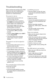
...the network chipset driver has been installed. ●● Verify if the network cable is turned on. ●● Select different inputs on the motherboard rear IO panel. ●● Remove secondary speakers/ headphones, HDMI cables, USB audio devices. ●● Test with another known working graphics ...the CMOS. ●● Use the secondary BIOS to lose all ATX power connectors like JPWR1~2 is connected from the power supply to the motherboard? ●● Some power supply units have a power button on the rear side, make sure the LAN port LEDs are heard, remove ...
...the network chipset driver has been installed. ●● Verify if the network cable is turned on. ●● Select different inputs on the motherboard rear IO panel. ●● Remove secondary speakers/ headphones, HDMI cables, USB audio devices. ●● Test with another known working graphics ...the CMOS. ●● Use the secondary BIOS to lose all ATX power connectors like JPWR1~2 is connected from the power supply to the motherboard? ●● Some power supply units have a power button on the rear side, make sure the LAN port LEDs are heard, remove ...


