User Guide
Page 3
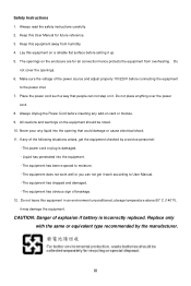
Always read the safety instructions carefully. 2. Do not cover the openings. 6. Never pour any of the power source and adjust properly 110/220V before setting it work according to moisture. - All cautions and warnings on card or module. 9. Replace only with the same or equivalent type recommended by a service personnel: - ...
Always read the safety instructions carefully. 2. Do not cover the openings. 6. Never pour any of the power source and adjust properly 110/220V before setting it work according to moisture. - All cautions and warnings on card or module. 9. Replace only with the same or equivalent type recommended by a service personnel: - ...
User Guide
Page 11
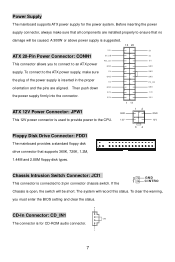
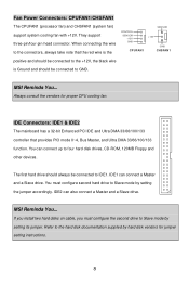
... supply for CD-ROM audio connector. L 7 Then push down GND 3.3 V the power supply firmly into the connector. 3.3 V 1 11 ATX 12V Power Connector: JPW1 GND 12 This 12V power connector is open, the switch will be caused. If the 2 GND 1 C I NTRO Chassis is ...ensure that all components are aligned. Chassis Intrusion Switch Connector: JCI1 This connector is suggested. 10 20 12V ATX 20-Pin Power Connector: CONN1 5V_SB This connector allows you must enter the BIOS setting and clear the status. R CD-In Connector: CD_IN1 GND The connector is inserted in the proper 5V...
... supply for CD-ROM audio connector. L 7 Then push down GND 3.3 V the power supply firmly into the connector. 3.3 V 1 11 ATX 12V Power Connector: JPW1 GND 12 This 12V power connector is open, the switch will be caused. If the 2 GND 1 C I NTRO Chassis is ...ensure that all components are aligned. Chassis Intrusion Switch Connector: JCI1 This connector is suggested. 10 20 12V ATX 20-Pin Power Connector: CONN1 5V_SB This connector allows you must enter the BIOS setting and clear the status. R CD-In Connector: CD_IN1 GND The connector is inserted in the proper 5V...
User Guide
Page 12
...the black wire is Ground and should always be connected to the hard disk documentation supplied by setting its jumper. MSI Reminds You... Refer to GND. Always consult the vendors for jumper setting instructions. 8 IDE1 can connect up to Slave mode by hard disk vendors for proper CPU ...cooling fan. IDE2 can also connect a Master and a Slave drive. MSI Reminds You... You must configure the second drive to four...
...the black wire is Ground and should always be connected to the hard disk documentation supplied by setting its jumper. MSI Reminds You... Refer to GND. Always consult the vendors for jumper setting instructions. 8 IDE1 can connect up to Slave mode by hard disk vendors for proper CPU ...cooling fan. IDE2 can also connect a Master and a Slave drive. MSI Reminds You... You must configure the second drive to four...
User Guide
Page 14
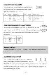
...are fully compliant with Serial ATA 1.0 specifications. PIN SIGNAL 1 GND 3 TXN 5 RXN 7 GND PIN SIGNAL 2 TXP 4 GND 6 RXP SATA2 71 SATA1 MSI Reminds You... Please do not fold the serial ATA cable in or receive data 3 SOUT Receive Data Transmit 4 DTR Serial out or transmit data 5 GND... Data 6 DSR Data Set Ready 7 RTS Request To Send Ring 8 CTS Clear To Send 9 RI Indicate 10 X X Serial ATA HDD Connectors: SATA1 & SATA2 The mainboard ...
...are fully compliant with Serial ATA 1.0 specifications. PIN SIGNAL 1 GND 3 TXN 5 RXN 7 GND PIN SIGNAL 2 TXP 4 GND 6 RXP SATA2 71 SATA1 MSI Reminds You... Please do not fold the serial ATA cable in or receive data 3 SOUT Receive Data Transmit 4 DTR Serial out or transmit data 5 GND... Data 6 DSR Data Set Ready 7 RTS Request To Send Ring 8 CTS Clear To Send 9 RI Indicate 10 X X Serial ATA HDD Connectors: SATA1 & SATA2 The mainboard ...
User Guide
Page 15
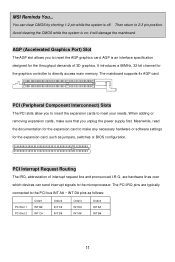
... the PCI bus INT A# ~ INT D# pins as jumpers, switches or BIOS configuration. When adding or removing expansion cards, make any necessary hardware or software settings for the throughput demands of interrupt request line and pronounced I-R-Q, are typically connected to meet your needs. You can send interrupt signals to insert the...Then return to directly access main memory. it will damage the mainboard. It introduces a 66MHz, 32-bit channel for the graphics controller to 2-3 pin position. MSI Reminds You... PCI Interrupt Request Routing The IRQ, abbreviation of 3D graphics.
... the PCI bus INT A# ~ INT D# pins as jumpers, switches or BIOS configuration. When adding or removing expansion cards, make any necessary hardware or software settings for the throughput demands of interrupt request line and pronounced I-R-Q, are typically connected to meet your needs. You can send interrupt signals to insert the...Then return to directly access main memory. it will damage the mainboard. It introduces a 66MHz, 32-bit channel for the graphics controller to 2-3 pin position. MSI Reminds You... PCI Interrupt Request Routing The IRQ, abbreviation of 3D graphics.
User Guide
Page 16
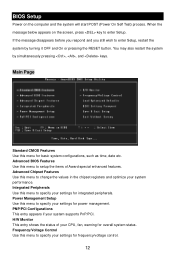
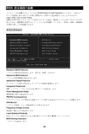
... frequency/voltage control. 12 Power Management Setup Use this menu to specify your settings for integrated peripherals. H/W Monitor This entry shows the status of Award special enhanced features. You may also restart the system by turning it OFF and ... the values in the chipset registers and optimize your system supports PnP/PCI. Advanced BIOS Features Use this menu to setup the items of your settings for power management. Integrated Peripherals Use this menu for overall system status. BIOS Setup Power on the screen, press key to enter Setup, restart the...
... frequency/voltage control. 12 Power Management Setup Use this menu to specify your settings for integrated peripherals. H/W Monitor This entry shows the status of Award special enhanced features. You may also restart the system by turning it OFF and ... the values in the chipset registers and optimize your system supports PnP/PCI. Advanced BIOS Features Use this menu to setup the items of your settings for power management. Integrated Peripherals Use this menu for overall system status. BIOS Setup Power on the screen, press key to enter Setup, restart the...
User Guide
Page 17
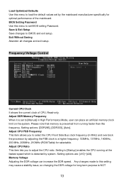
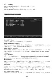
...CPU running faster than this frequency. Frequency/Voltage Control Current CPU Clock It shows the current clock of the mainboard. Setting options: [DDR266], [DDR333], [Auto]. Setting options are: [x10]~[x24]. Exit Without Saving Abandon all changes and exit setup. Read-only. Please note that memory... issue, so changing the DDR voltage for selectable. Load Optimized Defaults Use this menu to load the default values set BIOS setting Password. BIOS Setting Password Use this menu to set by adjusting the FSB clock to a higher frequency. 133MHz, 137MHz, 140MHz, 200 MHz, 206MHz, 210MHz (ROM...
...CPU running faster than this frequency. Frequency/Voltage Control Current CPU Clock It shows the current clock of the mainboard. Setting options: [DDR266], [DDR333], [Auto]. Setting options are: [x10]~[x24]. Exit Without Saving Abandon all changes and exit setup. Read-only. Please note that memory... issue, so changing the DDR voltage for selectable. Load Optimized Defaults Use this menu to load the default values set BIOS setting Password. BIOS Setting Password Use this menu to set by adjusting the FSB clock to a higher frequency. 133MHz, 137MHz, 140MHz, 200 MHz, 206MHz, 210MHz (ROM...
User Guide
Page 18
... EMI reduction. Remember to disable Spread Spectrum if you are reduced to Enabled for optimal system stability and performance. Spread Spectrum When the motherboard's clock generator pulses, the extreme values (spikes) of the pulses are overclocking because even a slight jitter can introduce a temporary boost ...in the field, allowing you do not have any EMI problem, leave the setting at 0.1V increment. AGP Voltage AGP voltage is used to increase the performance of your AGP display card when overclocking, but the ...
... EMI reduction. Remember to disable Spread Spectrum if you are reduced to Enabled for optimal system stability and performance. Spread Spectrum When the motherboard's clock generator pulses, the extreme values (spikes) of the pulses are overclocking because even a slight jitter can introduce a temporary boost ...in the field, allowing you do not have any EMI problem, leave the setting at 0.1V increment. AGP Voltage AGP voltage is used to increase the performance of your AGP display card when overclocking, but the ...

User Guide
Page 59
... 6 Request To Send Ring 8 Indicate 10 信号 SIN DTR DSR CTS X 定义 Serial in or receive data Serial out or transmit data Data Set Ready Clear To Send X Serial ATA HDD 接口:SATA1 & SATA2 2 Serial ATA Serial ATA 150 MB/s Serial ATA1.0 1 针脚 1 3 5 7 信号 GND...
... 6 Request To Send Ring 8 Indicate 10 信号 SIN DTR DSR CTS X 定义 Serial in or receive data Serial out or transmit data Data Set Ready Clear To Send X Serial ATA HDD 接口:SATA1 & SATA2 2 Serial ATA Serial ATA 150 MB/s Serial ATA1.0 1 针脚 1 3 5 7 信号 GND...

User Guide
Page 63
Load Optimized Defaults(载入 BIOS BIOS BIOS Setting Password(BIOS Save & Exit Setup CMOS Setup 程序。 Exit Without Saving CMOS Setup 程序。 59
Load Optimized Defaults(载入 BIOS BIOS BIOS Setting Password(BIOS Save & Exit Setup CMOS Setup 程序。 Exit Without Saving CMOS Setup 程序。 59

User Guide
Page 73
USB0+ GND KEY VCC 9 1 10 2 NC GND VCC USB1+ USB1- MSI 請注意,VC C 和 GND JCOM2 (選購) 16 位元組 FIFOs 的 16550A 9 1 10 2 PIN SIGNAL DESCRIPTION 1 DCD Data ... To Send Ring 9 RI Indicate PIN SIGNAL DESCRIPTION 2 SIN Serial in or receive data 4 DTR Serial out or transmit data 6 DSR Data Set Ready 8 CTS Clear To Send 10 X X 69 MSI Jumper 9 1 10 2 面板 USB JUSB1/JUSB2 USB2.0 連接器 JUSB1/JUSB2 Intel USB2.0 480Mbps,為 USB1.1 ...
USB0+ GND KEY VCC 9 1 10 2 NC GND VCC USB1+ USB1- MSI 請注意,VC C 和 GND JCOM2 (選購) 16 位元組 FIFOs 的 16550A 9 1 10 2 PIN SIGNAL DESCRIPTION 1 DCD Data ... To Send Ring 9 RI Indicate PIN SIGNAL DESCRIPTION 2 SIN Serial in or receive data 4 DTR Serial out or transmit data 6 DSR Data Set Ready 8 CTS Clear To Send 10 X X 69 MSI Jumper 9 1 10 2 面板 USB JUSB1/JUSB2 USB2.0 連接器 JUSB1/JUSB2 Intel USB2.0 480Mbps,為 USB1.1 ...

User Guide
Page 77
Load Optimized Defaults BIOS BIOS Setting Password(設定 BIOS BIOS 密碼。 Save & Exit Setup CMOS Exit Without Saving CMOS 73
Load Optimized Defaults BIOS BIOS Setting Password(設定 BIOS BIOS 密碼。 Save & Exit Setup CMOS Exit Without Saving CMOS 73
User Guide
Page 89
BIOS POST(Power On Self Test DEL press key to enter Setup. 、、
BIOS POST(Power On Self Test DEL press key to enter Setup. 、、
User Guide
Page 90
...]です。 Adjust CPU FSB Frequency CPU Front Side Bus 133MHz, 137MHz, 140MHz, 200 MHz, 206MHz, 210MHz です。 Adjust CPU Ratio CPU Setting to [Startup] enables the CPU running at the fastest speed which is detected by system x10]から[x24]です。 Memory Voltage DDR...
...]です。 Adjust CPU FSB Frequency CPU Front Side Bus 133MHz, 137MHz, 140MHz, 200 MHz, 206MHz, 210MHz です。 Adjust CPU Ratio CPU Setting to [Startup] enables the CPU running at the fastest speed which is detected by system x10]から[x24]です。 Memory Voltage DDR...

