
HDS Gen2 Touch FAQ
Page 3
How do I input video on my HDS9 or HDS12? To create a sonar log simply switch to sonar view, press Advanced then press Log sonar... HDS 9 and 12 units can choose a file name, save location, and logging criteria How do sonar logs? Once inside you will be presented with a menu where you can display video through the use of an optional adapter cable Whenever the cursor is displayed the very first item in the right hand menu becomes Clear Cursor How do I do I clear the cursor?
How do I input video on my HDS9 or HDS12? To create a sonar log simply switch to sonar view, press Advanced then press Log sonar... HDS 9 and 12 units can choose a file name, save location, and logging criteria How do sonar logs? Once inside you will be presented with a menu where you can display video through the use of an optional adapter cable Whenever the cursor is displayed the very first item in the right hand menu becomes Clear Cursor How do I do I clear the cursor?
Installation Manual
Page 3
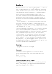
.... Preface As Navico is continuously improving this product, we retain the right to make changes to specifications without notice. and E.E.A. | 1 Please contact your display or system: www.lowrance.com Declarations and conformance This equipment is solely responsible for use the instrument and transducers in international waters as well as a separate document. Navico...
.... Preface As Navico is continuously improving this product, we retain the right to make changes to specifications without notice. and E.E.A. | 1 Please contact your display or system: www.lowrance.com Declarations and conformance This equipment is solely responsible for use the instrument and transducers in international waters as well as a separate document. Navico...

Installation Manual
Page 6
Contents 6 HDS Gen2 Touch overview 7 Front - connectors 9 SD card slot 10 Check the contents 11 Display Installation 11 Mounting location 12 Bracket mounting 13 Flush mounting 14 Research 14 Select a transducer location 15 Attaching the transducer 16 Adjusting the transducer 17 ... 22 NMEA 2000 device connection 24 NMEA 0183 device connection 25 Video In 25 Connecting video sources 26 Software setup 26 Sonar installation settings 28 Touch Screen Calibration 28 Software upgrades 29 Dimensional drawings 29 HDS 7 Gen2 Touch 29 HDS 9 Gen2 Touch 29 HDS 12 Gen2 Touch 4 | controls 8 Rear -
Contents 6 HDS Gen2 Touch overview 7 Front - connectors 9 SD card slot 10 Check the contents 11 Display Installation 11 Mounting location 12 Bracket mounting 13 Flush mounting 14 Research 14 Select a transducer location 15 Attaching the transducer 16 Adjusting the transducer 17 ... 22 NMEA 2000 device connection 24 NMEA 0183 device connection 25 Video In 25 Connecting video sources 26 Software setup 26 Sonar installation settings 28 Touch Screen Calibration 28 Software upgrades 29 Dimensional drawings 29 HDS 7 Gen2 Touch 29 HDS 9 Gen2 Touch 29 HDS 12 Gen2 Touch 4 | controls 8 Rear -

Installation Manual
Page 8
... and even digital switching. The ability to network over NMEA 2000 and ethernet allows access to the dash. Power should be mounted on 10.8 V - 17 V. 6 | HDS Gen2 Touch overview | HDS Gen2 Touch Installation Manual 1 HDS Gen2 Touch overview The HDS-7, HDS-9, and HDS-12 Gen2 Touch multifunction displays are charting ready, with built-in to data as well as control of boat power systems, the...
... and even digital switching. The ability to network over NMEA 2000 and ethernet allows access to the dash. Power should be mounted on 10.8 V - 17 V. 6 | HDS Gen2 Touch overview | HDS Gen2 Touch Installation Manual 1 HDS Gen2 Touch overview The HDS-7, HDS-9, and HDS-12 Gen2 Touch multifunction displays are charting ready, with built-in to data as well as control of boat power systems, the...
Installation Manual
Page 11
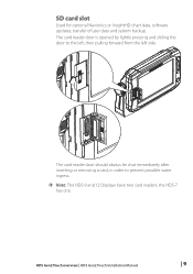
HDS Gen2 Touch overview | HDS Gen2 Touch Installation Manual | 9 The card reader door is opened by lightly pressing and sliding the door to prevent possible water ingress. ¼¼ Note: The HDS-9 and 12 Displays have two card readers, the HDS-7 has one. The card reader door should always be shut immediately after inserting or removing a card, in order to the left, then pulling forward from the left side. SD card slot Used for optional Navionics or InsightHD chart data, software updates, transfer of user data and system backup.
HDS Gen2 Touch overview | HDS Gen2 Touch Installation Manual | 9 The card reader door is opened by lightly pressing and sliding the door to prevent possible water ingress. ¼¼ Note: The HDS-9 and 12 Displays have two card readers, the HDS-7 has one. The card reader door should always be shut immediately after inserting or removing a card, in order to the left, then pulling forward from the left side. SD card slot Used for optional Navionics or InsightHD chart data, software updates, transfer of user data and system backup.
Installation Manual
Page 12
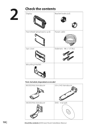
manuals 10 | Check the contents | HDS Gen2 Touch Installation Manual 2 Check the contents Display Bracket knobs (x2) Front Bezel (attached to unit) Power cable Sun cover Fasteners - #6 x 1.5" (4x) Mounting bracket Parts Included, dependent on model 83/200 KHz transducer LSS-2 HD transducer 50/200 KHz transducer DVD -
manuals 10 | Check the contents | HDS Gen2 Touch Installation Manual 2 Check the contents Display Bracket knobs (x2) Front Bezel (attached to unit) Power cable Sun cover Fasteners - #6 x 1.5" (4x) Mounting bracket Parts Included, dependent on model 83/200 KHz transducer LSS-2 HD transducer 50/200 KHz transducer DVD -
Installation Manual
Page 13
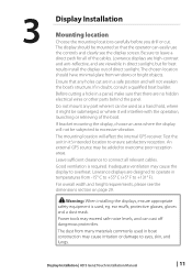
...to +131° F). Do not mount any holes cut . If bracket mounting the display, choose an area where the display will interfere with the operation, launching or retrieving of the boat. Lowrance displays are viewable in temperatures from -15° C to +55° C (+5°... Inadequate ventilation may cause irritation or damage to overcome poor reception areas. Warning: When installing the displays, ensure appropriate safety equipment is required. Display Installation | HDS Gen2 Touch Installation Manual | 11 The chosen location should be mounted so that any part where it can ...
...to +131° F). Do not mount any holes cut . If bracket mounting the display, choose an area where the display will interfere with the operation, launching or retrieving of the boat. Lowrance displays are viewable in temperatures from -15° C to +55° C (+5°... Inadequate ventilation may cause irritation or damage to overcome poor reception areas. Warning: When installing the displays, ensure appropriate safety equipment is required. Display Installation | HDS Gen2 Touch Installation Manual | 11 The chosen location should be mounted so that any part where it can ...
Installation Manual
Page 14
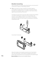
... in the bracket, and allows tilting of the knobs. Hand tighten only. Use only 304 or 316 stainless steel fasteners. Display Installation | HDS Gen2 Touch Installation Manual Bracket mounting Place the bracket in the desired mounting location, and use a pencil or permanent marker to mark drilling ...enough height to the bracket using bracket as template, and drill pilot holes. Use fasteners suited to allow tightening and loosening of the display. Mark the screw locations using the knobs. Also adequate space is too thin for self tappers, reinforce it, or mount bracket ...
... in the bracket, and allows tilting of the knobs. Hand tighten only. Use only 304 or 316 stainless steel fasteners. Display Installation | HDS Gen2 Touch Installation Manual Bracket mounting Place the bracket in the desired mounting location, and use a pencil or permanent marker to mark drilling ...enough height to the bracket using bracket as template, and drill pilot holes. Use fasteners suited to allow tightening and loosening of the display. Mark the screw locations using the knobs. Also adequate space is too thin for self tappers, reinforce it, or mount bracket ...
Installation Manual
Page 15
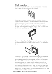
...ensure there is complete contact with the mounting surface. Sealant should be listing! Lastly, fit the bezel with the supplied screws. Display Installation | HDS Gen2 Touch Installation Manual | 13 If water-tightness is required, apply a thin, continuous bead of sealant to place. insert the outermost tabs...or horizontal reference. Flush mounting Check the template for scaling accuracy, using a tape measure or ruler against the ruler printed on the display, then gently press down the template. Check it clicks in to the slots on the template. 95.3 mm (7.50") MOUNTING SCREW...
...ensure there is complete contact with the mounting surface. Sealant should be listing! Lastly, fit the bezel with the supplied screws. Display Installation | HDS Gen2 Touch Installation Manual | 13 If water-tightness is required, apply a thin, continuous bead of sealant to place. insert the outermost tabs...or horizontal reference. Flush mounting Check the template for scaling accuracy, using a tape measure or ruler against the ruler printed on the display, then gently press down the template. Check it clicks in to the slots on the template. 95.3 mm (7.50") MOUNTING SCREW...
Installation Manual
Page 16
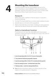
... rotation 3 Avoid mounting within 7.5cm (3") to determine the area of transom with cleanest flow (least bubbles) Select a transducer location The primary aim is moving. Display Installation | HDS Gen2 Touch Installation Manual undisturbed water flow 5 Planing strake - To function properly the transducer must be in the water at cruising speed to starboard of the most...
... rotation 3 Avoid mounting within 7.5cm (3") to determine the area of transom with cleanest flow (least bubbles) Select a transducer location The primary aim is moving. Display Installation | HDS Gen2 Touch Installation Manual undisturbed water flow 5 Planing strake - To function properly the transducer must be in the water at cruising speed to starboard of the most...
Installation Manual
Page 17
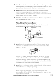
... on the hull can create large amounts of turbulence at least couple of millimetres (1/16ths of an inch) lower than the bottom of the hull. Display Installation | HDS Gen2 Touch Installation Manual | 15 Hold the transducer with bracket up to allow for transducer height adjustment. Drill pilot holes to pass the plug through. Attaching...
... on the hull can create large amounts of turbulence at least couple of millimetres (1/16ths of an inch) lower than the bottom of the hull. Display Installation | HDS Gen2 Touch Installation Manual | 15 Hold the transducer with bracket up to allow for transducer height adjustment. Drill pilot holes to pass the plug through. Attaching...
Installation Manual
Page 18
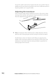
...;¼ Note: A transducer that moving , which worsen with tilting, try adjusting the height of the transducer relative to the transom of the transom. 16 | Display Installation | HDS Gen2 Touch Installation Manual Secure the cable to the hull at regular intervals using cable P clips or saddles and ensure that is too high it may be...
...;¼ Note: A transducer that moving , which worsen with tilting, try adjusting the height of the transducer relative to the transom of the transom. 16 | Display Installation | HDS Gen2 Touch Installation Manual Secure the cable to the hull at regular intervals using cable P clips or saddles and ensure that is too high it may be...
Installation Manual
Page 19
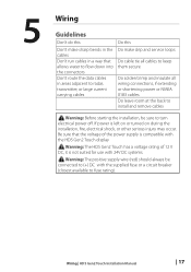
... fuse rating). Warning: Before starting the installation, be connected to (+) DC with the HDS Gen2 Touch display ! If power is compatible with the supplied fuse or a circuit breaker (closest available to turn electrical power off. Wiring | HDS Gen2 Touch Installation Manual | 17 Warning: The HDS Gen2 Touch has a voltage rating of the power supply is left on or turned on...
... fuse rating). Warning: Before starting the installation, be connected to (+) DC with the HDS Gen2 Touch display ! If power is compatible with the supplied fuse or a circuit breaker (closest available to turn electrical power off. Wiring | HDS Gen2 Touch Installation Manual | 17 Warning: The HDS Gen2 Touch has a voltage rating of the power supply is left on or turned on...
Installation Manual
Page 20
... Manual Connect Black to (+) DC using a 5 A fuse. This means that the modules are protected against reverse polarity, under voltage and over voltage. Power connection HDS Gen2 Touch displays are designed to be used to control the power state of the supplied power cable has two discrete cables exiting from it. The thickest cable ...
... Manual Connect Black to (+) DC using a 5 A fuse. This means that the modules are protected against reverse polarity, under voltage and over voltage. Power connection HDS Gen2 Touch displays are designed to be used to control the power state of the supplied power cable has two discrete cables exiting from it. The thickest cable ...
Installation Manual
Page 21
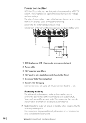
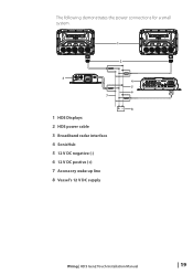
The following demonstrates the power connections for a small system. 1 2 3 7 1 HDS Displays 2 HDS power cable 3 Broadband radar interface 4 SonicHub 5 12 V DC negative (-) 6 12 V DC postive (+) 7 Accessory wake up line 8 Vessel's 12 V DC supply 4 5 6 +_ 8 Wiring | HDS Gen2 Touch Installation Manual | 19
The following demonstrates the power connections for a small system. 1 2 3 7 1 HDS Displays 2 HDS power cable 3 Broadband radar interface 4 SonicHub 5 12 V DC negative (-) 6 12 V DC postive (+) 7 Accessory wake up line 8 Vessel's 12 V DC supply 4 5 6 +_ 8 Wiring | HDS Gen2 Touch Installation Manual | 19
Installation Manual
Page 22
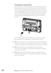
... 7 pin blue connector can be inserted in one orientation. Refer to the socket labelled 'Structure' . Transducer connection All Combo HDS Gen2 Touch displays have internal Broadband and StructureScan sonar (chart only units require an external module for connector location. Connector attached to cable is located... Note: Connectors are not in to the Overview section of an adaptor cable - see page 30. 20 | Wiring | HDS Gen2 Touch Installation Manual Navico transducers fitted with earlier LSS-1 transducers through use of this manual, or embossed labeling on the unit for sonar).
... 7 pin blue connector can be inserted in one orientation. Refer to the socket labelled 'Structure' . Transducer connection All Combo HDS Gen2 Touch displays have internal Broadband and StructureScan sonar (chart only units require an external module for connector location. Connector attached to cable is located... Note: Connectors are not in to the Overview section of an adaptor cable - see page 30. 20 | Wiring | HDS Gen2 Touch Installation Manual Navico transducers fitted with earlier LSS-1 transducers through use of this manual, or embossed labeling on the unit for sonar).

Installation Manual
Page 23
... NEP-2, it is auto sensing, meaning that the unit can connect to account the ports 'lost' when used to a HDS-9 or HDS-12 display, use of a crossover cable or switch. Connecting directly to a single device The ethernet port is possible to link two ... are fitted with 5 ethernet ports. Ethernet device connection Ethernet is used for maintaining a reliable, waterproof connection. The HDS-7 display has one ethernet device to a HDS-7 display, or two devices to interconnect high bandwidth devices such as radar, sonar, and other displays. Wiring | HDS Gen2 Touch Installation Manual | 21
... NEP-2, it is auto sensing, meaning that the unit can connect to account the ports 'lost' when used to a HDS-9 or HDS-12 display, use of a crossover cable or switch. Connecting directly to a single device The ethernet port is possible to link two ... are fitted with 5 ethernet ports. Ethernet device connection Ethernet is used for maintaining a reliable, waterproof connection. The HDS-7 display has one ethernet device to a HDS-7 display, or two devices to interconnect high bandwidth devices such as radar, sonar, and other displays. Wiring | HDS Gen2 Touch Installation Manual | 21
Installation Manual
Page 25
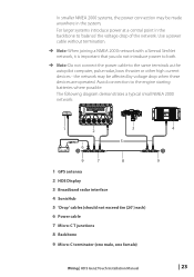
.... The following diagram demonstrates a typical small NMEA 2000 network: 1 2 3 5 _+ 12 V DC 6 T 9 7 8 1 GPS antenna 2 HDS Display 3 Broadband radar interface 4 SonicHub 5 'Drop' cables (should not exceed 6m (20') each) 6 Power cable 7 Micro-C T junctions 8 Backbone 9 Micro-C terminator (one male, one female) 4 T 9 Wiring | HDS Gen2 Touch Installation Manual | 23 Avoid connection to 'balance' the voltage drop of the network...
.... The following diagram demonstrates a typical small NMEA 2000 network: 1 2 3 5 _+ 12 V DC 6 T 9 7 8 1 GPS antenna 2 HDS Display 3 Broadband radar interface 4 SonicHub 5 'Drop' cables (should not exceed 6m (20') each) 6 Power cable 7 Micro-C T junctions 8 Backbone 9 Micro-C terminator (one male, one female) 4 T 9 Wiring | HDS Gen2 Touch Installation Manual | 23 Avoid connection to 'balance' the voltage drop of the network...
Installation Manual
Page 29
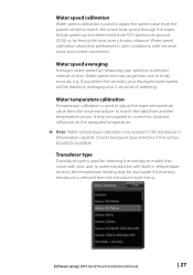
...Water speed calibration Water speed calibration is used for localized influences to match the actual boat speed through the water. Software setup | HDS Gen2 Touch Installation Manual | 27 If you select five seconds, your speed at a selected interval of sampling. Water speed intervals range from ...type Transducer type is used to adjust the water temperature value from GPS speed over ground (SOG) or by measuring your displayed water speed will be performed in temperature sensors, the temperature reading may be inaccurate if the wrong transducer is temperature capable....
...Water speed calibration Water speed calibration is used for localized influences to match the actual boat speed through the water. Software setup | HDS Gen2 Touch Installation Manual | 27 If you select five seconds, your speed at a selected interval of sampling. Water speed intervals range from ...type Transducer type is used to adjust the water temperature value from GPS speed over ground (SOG) or by measuring your displayed water speed will be performed in temperature sensors, the temperature reading may be inaccurate if the wrong transducer is temperature capable....
Installation Manual
Page 33
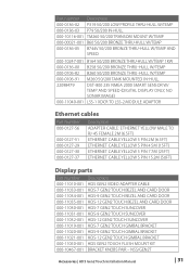
... (50ft) Display parts Part Number 000-11010-001 000-11033-001 000-11034-001 000-11035-001 000-11030-001 000-11031-001 000-11032-001 000-11019-001 000-11020-001 000-11021-001 000-11050-001 000-10467-001 Description HDS GEN2 VIDEO ADAPTER CABLE HDS-7 GEN2 TOUCH BEZEL AND CARD DOOR HDS-9 GEN2 TOUCH BEZEL AND...
... (50ft) Display parts Part Number 000-11010-001 000-11033-001 000-11034-001 000-11035-001 000-11030-001 000-11031-001 000-11032-001 000-11019-001 000-11020-001 000-11021-001 000-11050-001 000-10467-001 Description HDS GEN2 VIDEO ADAPTER CABLE HDS-7 GEN2 TOUCH BEZEL AND CARD DOOR HDS-9 GEN2 TOUCH BEZEL AND...


