
GT- Logic 4 Installation Manual
Page 2
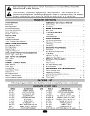
... (Belt Drive Model Operators 24 TESTING 25 MANUAL RELEASE 26-27 Emergency Disconnect System Model GT and T 26 Emergency Disconnect System Model APT 26 Emergency Disconnect System Model H, GH, J, and HJ 27 PROGRAMMING 28-35 Introduction to Order Repair Parts 36 TROUBLESHOOTING 37-40 Diagnostic Chart 37 Troubleshooting Guide 38 Troubleshooting Error Codes 39 Troubleshooting Radio Functionality 40 WIRING DIAGRAMS 41-42 Logic (Ver. 4.0) 1 Phase Wiring Diagram 41 Logic (Ver. 4.0) 3 Phase Wiring Diagram 42 ACCESSORIES 43 CONTROL CONNECTION DIAGRAM BACK COVER...
... (Belt Drive Model Operators 24 TESTING 25 MANUAL RELEASE 26-27 Emergency Disconnect System Model GT and T 26 Emergency Disconnect System Model APT 26 Emergency Disconnect System Model H, GH, J, and HJ 27 PROGRAMMING 28-35 Introduction to Order Repair Parts 36 TROUBLESHOOTING 37-40 Diagnostic Chart 37 Troubleshooting Guide 38 Troubleshooting Error Codes 39 Troubleshooting Radio Functionality 40 WIRING DIAGRAMS 41-42 Logic (Ver. 4.0) 1 Phase Wiring Diagram 41 Logic (Ver. 4.0) 3 Phase Wiring Diagram 42 ACCESSORIES 43 CONTROL CONNECTION DIAGRAM BACK COVER...

GT- Logic 4 Installation Manual
Page 13
... box (includes fasteners, track spacers, trolley, door arm assembly, front idler and header mounting bracket) 3-Button control station with electrical interlock for sensing device to reverse and auxiliary devices to the bottom edge of door. 13 Carton inventory/Operator specifications - Safety Edge (Optional Electric or pneumatic sensing device attached to open and close with open override. See page 29 for manual door operation Model H and GH Floor level chain hoist with LED...
... box (includes fasteners, track spacers, trolley, door arm assembly, front idler and header mounting bracket) 3-Button control station with electrical interlock for sensing device to reverse and auxiliary devices to the bottom edge of door. 13 Carton inventory/Operator specifications - Safety Edge (Optional Electric or pneumatic sensing device attached to open and close with open override. See page 29 for manual door operation Model H and GH Floor level chain hoist with LED...
GT- Logic 4 Installation Manual
Page 28
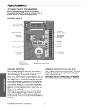
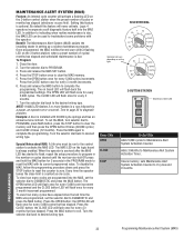
LEDs on the logic board are mounted directly on board push buttons to the operator, the following LED's will go out. When power is applied to function. LOGIC BOARD PUSH BUTTONS (OPEN, CLOSE, STOP) Open, Close and Stop buttons are provided to page 19 for programming and selecting wiring type) Main Motor Control Harness Connection LOGIC BOARD LED OVERVIEW NOTE: Before programming the logic board, set the operator's open and close limits. After the code has been provided the MAS LED will illuminate: STOP, CLOSE, OPEN, LMEP, 24Vac, RADIO, DATA, TIMER ENABLE, OLS MID, SLS...
LEDs on the logic board are mounted directly on board push buttons to the operator, the following LED's will go out. When power is applied to function. LOGIC BOARD PUSH BUTTONS (OPEN, CLOSE, STOP) Open, Close and Stop buttons are provided to page 19 for programming and selecting wiring type) Main Motor Control Harness Connection LOGIC BOARD LED OVERVIEW NOTE: Before programming the logic board, set the operator's open and close limits. After the code has been provided the MAS LED will illuminate: STOP, CLOSE, OPEN, LMEP, 24Vac, RADIO, DATA, TIMER ENABLE, OLS MID, SLS...
GT- Logic 4 Installation Manual
Page 30
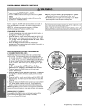
... logic board until completely closed. Remote controls adjusted and there are prohibited, except for changing the code setting or replacing the battery. The RADIO LED will be open and stop while opening. ATTENTION 3. NOTE: If Car Dealer mode is properly device. PRECAUCIÓN 3. The programming mode is exited if no obstructions to door travel. • NEVER permit children to add additional remote control(s). ERASING REMOTE CONTROLS Press and hold the remote control button until the RADIO LED flashes rapidly, then release remote control button. Repeat to operate...
... logic board until completely closed. Remote controls adjusted and there are prohibited, except for changing the code setting or replacing the battery. The RADIO LED will be open and stop while opening. ATTENTION 3. NOTE: If Car Dealer mode is properly device. PRECAUCIÓN 3. The programming mode is exited if no obstructions to door travel. • NEVER permit children to add additional remote control(s). ERASING REMOTE CONTROLS Press and hold the remote control button until the RADIO LED flashes rapidly, then release remote control button. Repeat to operate...
GT- Logic 4 Installation Manual
Page 31
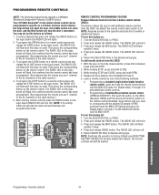
... and release the RADIO button. b. The RADIO LED will flash quickly 6 times. 4. With the door in the fully closed position (close the door, and the third button will still be lit. 3. The RADIO LED will turn off . 5. The RADIO LED on the logic board will flash, this confirms that the remote control has been programmed. (By programming the remote you use 1 channel of the 23 channels on the radio receiver.) 3. DATA SLOT 1 SLOT 2 OPEN CLOSE STOP Open Close Stop MER NABLE EDGE: OPEN CLOSE STOP COMMON REV MOTOR...
... and release the RADIO button. b. The RADIO LED will flash quickly 6 times. 4. With the door in the fully closed position (close the door, and the third button will still be lit. 3. The RADIO LED will turn off . 5. The RADIO LED on the logic board will flash, this confirms that the remote control has been programmed. (By programming the remote you use 1 channel of the 23 channels on the radio receiver.) 3. DATA SLOT 1 SLOT 2 OPEN CLOSE STOP Open Close Stop MER NABLE EDGE: OPEN CLOSE STOP COMMON REV MOTOR...
GT- Logic 4 Installation Manual
Page 32
..., an operator error occurred. Once programmed, the MAS notifies the end user (with 30,000 cycle springs and has an annual service contract. Press and release the MAS button to exit. The OPEN LED will flash once for every (3) months that has elapsed. NOTE: If MAS LED flashes 2 or more flashes in setting up a routine maintenance program. Special Notes about MAS: A 5th wire must be used to troubleshoot some problems with...
..., an operator error occurred. Once programmed, the MAS notifies the end user (with 30,000 cycle springs and has an annual service contract. Press and release the MAS button to exit. The OPEN LED will flash once for every (3) months that has elapsed. NOTE: If MAS LED flashes 2 or more flashes in setting up a routine maintenance program. Special Notes about MAS: A 5th wire must be used to troubleshoot some problems with...

GT- Logic 4 Installation Manual
Page 38
... may need to see wiring diagram Off Board Relays). ➤ Replace logic board. If Relay A or B lights and the door does not move in series. Remove any obstructions, check the safety device wires for loose connections. Check that the board is malfunctioning f) Motor thermal overload tripped g) Possible accessory malfunction h) Off Board relay may need to be a Mid Stop set MOST OF THE WAY correctly TOWARDS A LIMIT THEN STOP. THE DOOR WILL OPEN SOME BUT NOT...
... may need to see wiring diagram Off Board Relays). ➤ Replace logic board. If Relay A or B lights and the door does not move in series. Remove any obstructions, check the safety device wires for loose connections. Check that the board is malfunctioning f) Motor thermal overload tripped g) Possible accessory malfunction h) Off Board relay may need to be a Mid Stop set MOST OF THE WAY correctly TOWARDS A LIMIT THEN STOP. THE DOOR WILL OPEN SOME BUT NOT...

GT- Logic 4 Installation Manual
Page 39
.... ERROR CODE E1 E2 E3 E4 E5 E6 E7 E8 E9 E10 DISPLAY 1 blink 2 blinks DESCRIPTION MAS triggered (cycles or months) No RPM input during opening 3 blinks (MRT) Maximum Run Time timed out 4 blinks Obstruction sensed on closing 5 blinks 6 blinks 7 blinks 8 blinks Stuck button pressed for any faults (i.e., Bad Limit switch), manually learn Max Run Timer (page 35) OR reset factory defaults (page 35). The door stops before it will continue to troubleshoot some problems with...
.... ERROR CODE E1 E2 E3 E4 E5 E6 E7 E8 E9 E10 DISPLAY 1 blink 2 blinks DESCRIPTION MAS triggered (cycles or months) No RPM input during opening 3 blinks (MRT) Maximum Run Time timed out 4 blinks Obstruction sensed on closing 5 blinks 6 blinks 7 blinks 8 blinks Stuck button pressed for any faults (i.e., Bad Limit switch), manually learn Max Run Timer (page 35) OR reset factory defaults (page 35). The door stops before it will continue to troubleshoot some problems with...
GT- Logic 4 Installation Manual
Page 40
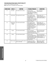
...ERROR CODE DISPLAY SYMPTOM POSSIBLE PROBLEM CORRECTION R1 Quick Flash No response from the remote Cannot recognize remote - OR- search reveals that remote is compatible with the operator. remote(s) - interference interfering with the check antenna connections. NOTE: Radio receiver is already learned. When the remote learned remotes and button is not compatible with it. This remote already has a A user enters RADIO function function associated with the operator. TROUBLESHOOTING 40 Troubleshooting radio functionality R6 LMEP LED flashes Cannot close...
...ERROR CODE DISPLAY SYMPTOM POSSIBLE PROBLEM CORRECTION R1 Quick Flash No response from the remote Cannot recognize remote - OR- search reveals that remote is compatible with the operator. remote(s) - interference interfering with the check antenna connections. NOTE: Radio receiver is already learned. When the remote learned remotes and button is not compatible with it. This remote already has a A user enters RADIO function function associated with the operator. TROUBLESHOOTING 40 Troubleshooting radio functionality R6 LMEP LED flashes Cannot close...
T LOGIC VERSION 2 Manual
Page 2
... List 2 Motor Specification 3 Electrical Specifications 3 Mechanical Specifications 3 Safety Specifications 3 Weights & Dimensions 3 PREPARATION Track Assembly 4 Powerhead Attachment 4 Trolley Carriage/ Chain Attachment 4 INSTALLATION INSTRUCTIONS Mounting Header Bracket 5 Mounting Operator 5 Operator Support 6 Straight Arm Attachment 6 ENTRAPMENT PROTECTION ACCESSORIES Sensing Edges & Photo Eyes 7 LIMIT SWITCH ADJUSTMENT Limit Location 7 Adjustment 7 POWER & CONTROL WIRING Safety Warnings 8 Power Wiring 9 Ground Wiring 9 Control Station Wiring 9 Radio Controls 9 Mounting...
... List 2 Motor Specification 3 Electrical Specifications 3 Mechanical Specifications 3 Safety Specifications 3 Weights & Dimensions 3 PREPARATION Track Assembly 4 Powerhead Attachment 4 Trolley Carriage/ Chain Attachment 4 INSTALLATION INSTRUCTIONS Mounting Header Bracket 5 Mounting Operator 5 Operator Support 6 Straight Arm Attachment 6 ENTRAPMENT PROTECTION ACCESSORIES Sensing Edges & Photo Eyes 7 LIMIT SWITCH ADJUSTMENT Limit Location 7 Adjustment 7 POWER & CONTROL WIRING Safety Warnings 8 Power Wiring 9 Ground Wiring 9 Control Station Wiring 9 Radio Controls 9 Mounting...

T LOGIC VERSION 2 Manual
Page 9
... OF MAINTENANCE THE AREA MUST BE CLEARED AND SECURED, AT THAT TIME THE UNIT MAY BE RETURNED TO SERVICE. Mount Control Stations no further than (12") from the door enclosure. 3. INSTALL POWER WIRING & CONTROL STATION (CONT'D) POWER WIRING POWER WIRING CONNECTIONS 1. Be sure to either side of door travel and then Press the STOP button. Be sure to close a fully open the door or reset the timer to run all power wires through the conduit hole in the electrical box...
... OF MAINTENANCE THE AREA MUST BE CLEARED AND SECURED, AT THAT TIME THE UNIT MAY BE RETURNED TO SERVICE. Mount Control Stations no further than (12") from the door enclosure. 3. INSTALL POWER WIRING & CONTROL STATION (CONT'D) POWER WIRING POWER WIRING CONNECTIONS 1. Be sure to either side of door travel and then Press the STOP button. Be sure to close a fully open the door or reset the timer to run all power wires through the conduit hole in the electrical box...

T LOGIC VERSION 2 Manual
Page 16
... the Failsafe wiring modes, or Timer To Close wiring modes (TS, T, FSTS), a LiftMaster self monitoring safety device must be installed to operate SAFE door. User set midstop. Self Monitoring safety device must be reversed while closing by activating an opening device without the need to the full open T input to operate 1 2 3 4 door. The FSTS single button station opens the door to use the operator in travel. Recommended LiftMaster Self Monitoring Safety Devices: CPS-L NEMA 1 Direct Connect Eyes CPS-LN4 NEMA 4 Direct Connect Eyes NOTE...
... the Failsafe wiring modes, or Timer To Close wiring modes (TS, T, FSTS), a LiftMaster self monitoring safety device must be installed to operate SAFE door. User set midstop. Self Monitoring safety device must be reversed while closing by activating an opening device without the need to the full open T input to operate 1 2 3 4 door. The FSTS single button station opens the door to use the operator in travel. Recommended LiftMaster Self Monitoring Safety Devices: CPS-L NEMA 1 Direct Connect Eyes CPS-LN4 NEMA 4 Direct Connect Eyes NOTE...
T-LOGIC 3 Manual
Page 2
... External Radio Wiring Connections 13 Mounting Instructions 13 DIAGRAMS Standard Power & Control Connection Diagrams 14 1 Phase Wiring Diagram 15 3 Phase Wiring Diagram 16 Logic Board 17 PROGRAMMING Logic Control Pushbuttons 18 Determine and Set Wiring Type 18 Failsafe Wiring Types 19 Self-Monitoring Safety Device Options 19 Programming Remotes 20-21 Maintenance Alert System (MAS 22 Mid Stop 23 Timer To Close 23-24 Car Dealer Mode 24 AUTOMATICALLY LEARNED PROGRAMMING Auxiliary Reversal System/RPM Sensor 25 Maximum Run Timer (MRT 25 OPTIONAL PROGRAMMING Red/Green Warning Light...
... External Radio Wiring Connections 13 Mounting Instructions 13 DIAGRAMS Standard Power & Control Connection Diagrams 14 1 Phase Wiring Diagram 15 3 Phase Wiring Diagram 16 Logic Board 17 PROGRAMMING Logic Control Pushbuttons 18 Determine and Set Wiring Type 18 Failsafe Wiring Types 19 Self-Monitoring Safety Device Options 19 Programming Remotes 20-21 Maintenance Alert System (MAS 22 Mid Stop 23 Timer To Close 23-24 Car Dealer Mode 24 AUTOMATICALLY LEARNED PROGRAMMING Auxiliary Reversal System/RPM Sensor 25 Maximum Run Timer (MRT 25 OPTIONAL PROGRAMMING Red/Green Warning Light...
T-LOGIC 3 Manual
Page 19
... which time the operator enters the B2 mode. and 3-Button Remote Controls. (NOTE: Requires self monitoring photo eyes to activate the Timer To Close. See Self Monitoring Safety Device Options. Auxiliary devices are any of the following failsafe wiring types. C2 Failsafe Same functions as D1. and 3-Button Remote Controls. (NOTE: Requires self monitoring photo eyes to operate door for open, close , and stop . Radio controls allowing open, close , and stop programming. Self Monitoring safety device must be reversed while closing...
... which time the operator enters the B2 mode. and 3-Button Remote Controls. (NOTE: Requires self monitoring photo eyes to activate the Timer To Close. See Self Monitoring Safety Device Options. Auxiliary devices are any of the following failsafe wiring types. C2 Failsafe Same functions as D1. and 3-Button Remote Controls. (NOTE: Requires self monitoring photo eyes to operate door for open, close , and stop . Radio controls allowing open, close , and stop programming. Self Monitoring safety device must be reversed while closing...

T-LOGIC 3 Manual
Page 29
... help check correct wiring. STOP BUTTON LED IS NOT ON a) Control station not connected or wired ➤ Check wiring to reset fault. THE DOOR WILL MOVE ABOUT A FOOT THEN STOP. Remove any obstructions, check the safety device wires for continuity and shorts. ➤ Unlearn the photo eyes from power source. ➤ Use the OPEN, CLOSE and STOP LEDs to be replaced (see wiring diagram Off Board Relays). ➤ Disconnect all devices, reattach them one at a time testing for...
... help check correct wiring. STOP BUTTON LED IS NOT ON a) Control station not connected or wired ➤ Check wiring to reset fault. THE DOOR WILL MOVE ABOUT A FOOT THEN STOP. Remove any obstructions, check the safety device wires for continuity and shorts. ➤ Unlearn the photo eyes from power source. ➤ Use the OPEN, CLOSE and STOP LEDs to be replaced (see wiring diagram Off Board Relays). ➤ Disconnect all devices, reattach them one at a time testing for...

T-LOGIC 3 Manual
Page 30
... error at invalid time Operator will flash. There may be set to troubleshoot some problems with the operator. Stuck key must run as long as an input. Check relays and the drive circuitry to 6 blinks than Stuck key on the MAS LED. TROUBLESHOOTING ERROR CODES Logic 3.0 operators incorporate a self diagnostic feature built into the MAS LED. In addition to indicating when routing maintenance is cleared or connected. 1. the 3-button station or any faults (i.e., Bad Limit switch), manually learn...
... error at invalid time Operator will flash. There may be set to troubleshoot some problems with the operator. Stuck key must run as long as an input. Check relays and the drive circuitry to 6 blinks than Stuck key on the MAS LED. TROUBLESHOOTING ERROR CODES Logic 3.0 operators incorporate a self diagnostic feature built into the MAS LED. In addition to indicating when routing maintenance is cleared or connected. 1. the 3-button station or any faults (i.e., Bad Limit switch), manually learn...

T-LOGIC 3 Manual
Page 31
... direct connect eyes or a CPS3 device - change the function, erase all learned remotes A user enters RADIO function and re-learn the desired learning mode but the RADIO LED only flashes briefly and there is already learned. TROUBLESHOOTING RADIO FUNCTIONALITY The error codes will display at the radio LED. Replace battery - Replace battery - OR eliminate interference - ORobtain a qualified remote. 2 Blinks No free records - To learning and selects the function change to a mode that remote is no remote. DISPLAY POSSIBLE PROBLEM CORRECTION Quick Flash Unlearned remote A user...
... direct connect eyes or a CPS3 device - change the function, erase all learned remotes A user enters RADIO function and re-learn the desired learning mode but the RADIO LED only flashes briefly and there is already learned. TROUBLESHOOTING RADIO FUNCTIONALITY The error codes will display at the radio LED. Replace battery - Replace battery - OR eliminate interference - ORobtain a qualified remote. 2 Blinks No free records - To learning and selects the function change to a mode that remote is no remote. DISPLAY POSSIBLE PROBLEM CORRECTION Quick Flash Unlearned remote A user...

T-Quick Start Guide for L3 Manual
Page 2
... the chain to the door bracket with adjustments. Attach arm assembly to achieve proper adjustment. (Two nuts and a lock washer, two master links) ()Provide a mounting pad for each application is unique, it should generally be comprehensive. Adjust the limit switches to ensure that the take -up . (Two -1" bolts/nuts per spacer) °Install the idler wheel assembly in the electrical box enclosure. Reinstall cotter pin when finished. ®Radio programming and troubleshooting instructions inside cover...
... the chain to the door bracket with adjustments. Attach arm assembly to achieve proper adjustment. (Two nuts and a lock washer, two master links) ()Provide a mounting pad for each application is unique, it should generally be comprehensive. Adjust the limit switches to ensure that the take -up . (Two -1" bolts/nuts per spacer) °Install the idler wheel assembly in the electrical box enclosure. Reinstall cotter pin when finished. ®Radio programming and troubleshooting instructions inside cover...
T LOGIC CONTROL VERSION 2 Manual
Page 2
... Wiring 14 STANDARD PROGRAMMING Wiring Type 15 & 16 Self Monitoring Safety Devices 16 RPM Sensor 17 Maximum Run Timer 17 Maintenance Alert System 18 OPTIONAL PROGRAMMING Mid Stop 18 Timer to ensure that all safety instructions. Because each application is unique, it is the responsibility of the purchaser, designer, installer and end user to Close 19 Red Green Warning Lights 19 Board Illustration 20 REPLACEMENT PARTS & MAINTENANCE Trouble Shooting Guide 21 & 22 Maintenance Schedule 23 Customer Service Contact Information 23 Electrical Box parts...
... Wiring 14 STANDARD PROGRAMMING Wiring Type 15 & 16 Self Monitoring Safety Devices 16 RPM Sensor 17 Maximum Run Timer 17 Maintenance Alert System 18 OPTIONAL PROGRAMMING Mid Stop 18 Timer to ensure that all safety instructions. Because each application is unique, it is the responsibility of the purchaser, designer, installer and end user to Close 19 Red Green Warning Lights 19 Board Illustration 20 REPLACEMENT PARTS & MAINTENANCE Trouble Shooting Guide 21 & 22 Maintenance Schedule 23 Customer Service Contact Information 23 Electrical Box parts...

T LOGIC CONTROL VERSION 2 Manual
Page 16
... of the Failsafe wiring modes, or Timer To Close wiring modes (TS, T, FSTS), a LiftMaster self monitoring safety device must be reversed while closing by activating an opening device without the need to use the operator in any devices that causes the door to open, except a 1 2 3 4 reversing device, activates the Timer To Close. The single button station opens the door to the full open limit bypassing the mid stop . D1 FAIL SAFE 1 2 3 4 OFF E2 Failsafe 2 Button, 3 Button Radio Control Same functions...
... of the Failsafe wiring modes, or Timer To Close wiring modes (TS, T, FSTS), a LiftMaster self monitoring safety device must be reversed while closing by activating an opening device without the need to use the operator in any devices that causes the door to open, except a 1 2 3 4 reversing device, activates the Timer To Close. The single button station opens the door to the full open limit bypassing the mid stop . D1 FAIL SAFE 1 2 3 4 OFF E2 Failsafe 2 Button, 3 Button Radio Control Same functions...


