
SL595 Manual
Page 2
... 23 AVERTISSEMENT Solenoid Actuated Brake 24 Friction Clutch 24 HARDWARE KIT SL585/SL595 (K77-34846) Control Board Programming and Features 24-25 AVER Troubleshooting 26-27 Self-Regulating Heater Accessory 28 Single Phase Wiring Diagram 29 Single Phase Schematic 30 Three Phase Wiring Diagram 31 Three Phase Schematic 32 DESCRIPTION Safety Gate Brochure Gate Bracket...
... 23 AVERTISSEMENT Solenoid Actuated Brake 24 Friction Clutch 24 HARDWARE KIT SL585/SL595 (K77-34846) Control Board Programming and Features 24-25 AVER Troubleshooting 26-27 Self-Regulating Heater Accessory 28 Single Phase Wiring Diagram 29 Single Phase Schematic 30 Three Phase Wiring Diagram 31 Three Phase Schematic 32 DESCRIPTION Safety Gate Brochure Gate Bracket...
SL595 Manual
Page 8
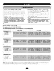
... should be reviewed for suitability of wire installation. Local codes and conditions must be returned to service. Operator MUST be properly grounded and connected in the area near the operator MUST NOT be run the operator without consulting the wiring diagram. NOTE: The operator should be ...visible and clearly labeled. • ALL power and control wiring MUST be performed until disconnecting the electrical power and locking-out the power via the...
... should be reviewed for suitability of wire installation. Local codes and conditions must be returned to service. Operator MUST be properly grounded and connected in the area near the operator MUST NOT be run the operator without consulting the wiring diagram. NOTE: The operator should be ...visible and clearly labeled. • ALL power and control wiring MUST be performed until disconnecting the electrical power and locking-out the power via the...
SL595 Manual
Page 12
... operators will run reversed. MANUAL DISCONNECT MODEL SL585 DISENGAGEMENT: RE-ENGAGEMENT: Rotate disconnect handle 90˚ to electrical wiring diagrams on page 8 for engagement.) MODEL SL595 DISENGAGEMENT: RE-ENGAGEMENT: Open the hinged door and pull the disconnect lever and lock it in place. Secure all...from the factory as 3/4" and 1" knock outs for engagement.) Pull the handle to release 12 ON/OFF SWITCH POWER WIRING NOTES: Before running power wiring refer to original position. (Some operator output sprocket rotation may be moved manually. To correct this situation, shut off ...
... operators will run reversed. MANUAL DISCONNECT MODEL SL585 DISENGAGEMENT: RE-ENGAGEMENT: Rotate disconnect handle 90˚ to electrical wiring diagrams on page 8 for engagement.) MODEL SL595 DISENGAGEMENT: RE-ENGAGEMENT: Open the hinged door and pull the disconnect lever and lock it in place. Secure all...from the factory as 3/4" and 1" knock outs for engagement.) Pull the handle to release 12 ON/OFF SWITCH POWER WIRING NOTES: Before running power wiring refer to original position. (Some operator output sprocket rotation may be moved manually. To correct this situation, shut off ...
SL595 Manual
Page 17
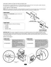
... R4 Accessory Terminal Block 1 2 3 4 5 6 7 8 9 10 11 12 13 14 15 16 17 18 19 20 24 Vac Control Board SINGLE PHASE ELECTRICAL BOX NOTE: See wiring diagrams shipped with the gate while operating the controls where the user has full view of gate operation. * We strongly recommend that are contrary to operate...
... R4 Accessory Terminal Block 1 2 3 4 5 6 7 8 9 10 11 12 13 14 15 16 17 18 19 20 24 Vac Control Board SINGLE PHASE ELECTRICAL BOX NOTE: See wiring diagrams shipped with the gate while operating the controls where the user has full view of gate operation. * We strongly recommend that are contrary to operate...
SL595 Manual
Page 28
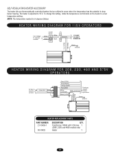
... controls On/Off Switch White ON White Black Black OFF L1 1 PHASE L2 115 VOLT POWER IN Green Ground Black (N) Black (T1) HEATER WIRING DIAGRAM FOR 208, 230, 460 AND 575V OPERATORS 24 Vac to a new temperature setting. Transformer 100VA with 3.2A fuse 1 (208V, 230V and ... Blue Yellow Grey (575V) Violet (480V) Orange (230V) Red (208V) White (Common) White (Common) Black (120V) Terminate unused transfer input wires Green Ground Black (N) Black (T1) HEATER REPLACEMENT PARTS PART NUMBER 21-15453-1 50-18423 DESCRIPTION QTY. The heater is in areas where the temperature...
... controls On/Off Switch White ON White Black Black OFF L1 1 PHASE L2 115 VOLT POWER IN Green Ground Black (N) Black (T1) HEATER WIRING DIAGRAM FOR 208, 230, 460 AND 575V OPERATORS 24 Vac to a new temperature setting. Transformer 100VA with 3.2A fuse 1 (208V, 230V and ... Blue Yellow Grey (575V) Violet (480V) Orange (230V) Red (208V) White (Common) White (Common) Black (120V) Terminate unused transfer input wires Green Ground Black (N) Black (T1) HEATER REPLACEMENT PARTS PART NUMBER 21-15453-1 50-18423 DESCRIPTION QTY. The heater is in areas where the temperature...
SL595 Manual
Page 29
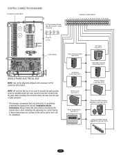
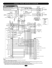
...GROUNDED (W) (W) 115V ONLY O/L (BK) (BK) 208/230V ONLY (W) 4B3 5A 6 (W) 4A3 1B 2 (W) 2A1 115V MOTOR CONNECTION (PU) (SL595 RD) (BL) (YE) (SL595 WH) (GY) SL595 GN) 42 8 5 13 (SEE NOTE 3) (BL/BK) (BK) 115V BRAKE (BK) SOLENOID (BL/BK) 1 PHASE POWER IN GROUND (...5) 4 (GN) 6 (WH) 7 (RD) 8 (BK) 9 (BRN) 10 (GY) FREE EXIT LOOP HARNESS 10 PIN - 1,2,3,5 CAPPED 4 - SINGLE PHASE WIRING DIAGRAM WARNING To protect against fire and electrocution: • DISCONNECT power BEFORE installing or servicing operator. • Replace ONLY with an additional internal pilot duty thermal...
...GROUNDED (W) (W) 115V ONLY O/L (BK) (BK) 208/230V ONLY (W) 4B3 5A 6 (W) 4A3 1B 2 (W) 2A1 115V MOTOR CONNECTION (PU) (SL595 RD) (BL) (YE) (SL595 WH) (GY) SL595 GN) 42 8 5 13 (SEE NOTE 3) (BL/BK) (BK) 115V BRAKE (BK) SOLENOID (BL/BK) 1 PHASE POWER IN GROUND (...5) 4 (GN) 6 (WH) 7 (RD) 8 (BK) 9 (BRN) 10 (GY) FREE EXIT LOOP HARNESS 10 PIN - 1,2,3,5 CAPPED 4 - SINGLE PHASE WIRING DIAGRAM WARNING To protect against fire and electrocution: • DISCONNECT power BEFORE installing or servicing operator. • Replace ONLY with an additional internal pilot duty thermal...

SL595 Manual
Page 31
...AB CD 230V CONNECTION (GY) (SL595 GN) (BK) (PU) (SL595 RD) (BK) (YE) (SL595 WH) 1 74 2 85 3 96 460V CONNECTION (GY) (SL595 GN) 1 (BK) 2 (PU) (SL595 RD) (BK) (YE) (SL595 WH) 3 (SEE NOTE 3) 74 85 96 575V CONNECTION (GY) (SL595 GN) 1 (BK) 2 (PU) (SL595 RD) (BK) (YE) (SL595 WH) 3 (SEE NOTE 3)... OPEN (GN) 8 INTERRUPT (SAFETY) OBS. Secondary 24V 60VA. 2. Transformer primary voltage is the same as the operator line voltage. THREE PHASE WIRING DIAGRAM 3 PHASE POWER IN ON/OFF SWITCH L1 (BK) L2 (BK) L3 (BK) GROUND (GN) WARNING To protect against fire and electrocution: ...
...AB CD 230V CONNECTION (GY) (SL595 GN) (BK) (PU) (SL595 RD) (BK) (YE) (SL595 WH) 1 74 2 85 3 96 460V CONNECTION (GY) (SL595 GN) 1 (BK) 2 (PU) (SL595 RD) (BK) (YE) (SL595 WH) 3 (SEE NOTE 3) 74 85 96 575V CONNECTION (GY) (SL595 GN) 1 (BK) 2 (PU) (SL595 RD) (BK) (YE) (SL595 WH) 3 (SEE NOTE 3)... OPEN (GN) 8 INTERRUPT (SAFETY) OBS. Secondary 24V 60VA. 2. Transformer primary voltage is the same as the operator line voltage. THREE PHASE WIRING DIAGRAM 3 PHASE POWER IN ON/OFF SWITCH L1 (BK) L2 (BK) L3 (BK) GROUND (GN) WARNING To protect against fire and electrocution: ...


