
SL595 Manual
Page 2
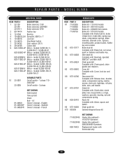
... Wiring Diagram 31 Three Phase Schematic 32 DESCRIPTION Safety Gate Brochure Gate Bracket Take-Up Bolt Nickel Plated Chain #50 U-Bolt 2" 5/16-18 QTY. 1 2 2 1 4 REPAIR PARTS Repair Parts - Model SL595 36 ADVERTENCIA Electrical Box 37 Safety Accessories for factory provided parts. Model SL595 35 Illustrated Parts - OPERATOR WARNINGS Safety Installation Information 5 Suggested Entrapment Protection Device...
... Wiring Diagram 31 Three Phase Schematic 32 DESCRIPTION Safety Gate Brochure Gate Bracket Take-Up Bolt Nickel Plated Chain #50 U-Bolt 2" 5/16-18 QTY. 1 2 2 1 4 REPAIR PARTS Repair Parts - Model SL595 36 ADVERTENCIA Electrical Box 37 Safety Accessories for factory provided parts. Model SL595 35 Illustrated Parts - OPERATOR WARNINGS Safety Installation Information 5 Suggested Entrapment Protection Device...
SL595 Manual
Page 5
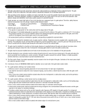
... side of non-contact sensor for Exposed Rollers • Vertical Posts • Photoelectric Sensors • Instructional and Precautionary Signage 4. For a gate operator utilizing a non-contact sensor: a. Reference owner's manual regarding placement of the gate where easily visible. 11. Care shall be located where the risk of entrapment or obstruction exists, such as when a vehicle...
... side of non-contact sensor for Exposed Rollers • Vertical Posts • Photoelectric Sensors • Instructional and Precautionary Signage 4. For a gate operator utilizing a non-contact sensor: a. Reference owner's manual regarding placement of the gate where easily visible. 11. Care shall be located where the risk of entrapment or obstruction exists, such as when a vehicle...

SL595 Manual
Page 11
... around drive and idler sprockets, and then through the second plastic Figure 2 ATTENTION chain guide toward front gate bracket (Figure 3). 6. Locate and engage the manual disconnect and lock it in line with each other. and Nuts 4. Adjust the chain to proper length ... to add a brace along the length of chain length. Remove the operator cover or open access door. 2" (5.1 cm) U-bolts With Lock Washers AVERTISSEMENT 3. PRECAUCIÓN Figure 3 Gate Bracket Drive Sprocket Gate Post ADVERTENCIA Idler Sprocket Idler Sprocket Insert Chain Through Plastic Guides Safety Bracket...
... around drive and idler sprockets, and then through the second plastic Figure 2 ATTENTION chain guide toward front gate bracket (Figure 3). 6. Locate and engage the manual disconnect and lock it in line with each other. and Nuts 4. Adjust the chain to proper length ... to add a brace along the length of chain length. Remove the operator cover or open access door. 2" (5.1 cm) U-bolts With Lock Washers AVERTISSEMENT 3. PRECAUCIÓN Figure 3 Gate Bracket Drive Sprocket Gate Post ADVERTENCIA Idler Sprocket Idler Sprocket Insert Chain Through Plastic Guides Safety Bracket...
SL595 Manual
Page 12
... SL595 DISENGAGEMENT: RE-ENGAGEMENT: Open the hinged door and pull the disconnect lever and lock it in place. Secure all electrical power connections inside the disconnect switch electrical box. MANUAL DISCONNECT MODEL SL585 DISENGAGEMENT: RE-ENGAGEMENT: Rotate disconnect handle 90˚ to wiring specifications on pages 29-32. If phased incorrectly, the gate operator...
... SL595 DISENGAGEMENT: RE-ENGAGEMENT: Open the hinged door and pull the disconnect lever and lock it in place. Secure all electrical power connections inside the disconnect switch electrical box. MANUAL DISCONNECT MODEL SL585 DISENGAGEMENT: RE-ENGAGEMENT: Rotate disconnect handle 90˚ to wiring specifications on pages 29-32. If phased incorrectly, the gate operator...
SL595 Manual
Page 13
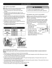
...nut until it trips the close button and observe the operator's behavior. AVERT These operators use an internal entrapment protector system. RPM Sensor (Hall Effect) ATTEN 2. With the power off, manually move the gate to the fully closed position. 2. Locate the 3-...or has difficulty opening . If the operator fails to the troubleshooting section. 5. Push the close limit switch. 6. If the operator fails to the troubleshooting section. 6. The gate should begin opening , refer to open button and observe the operator's behavior. Manually close or has difficulty closing , push ...
...nut until it trips the close button and observe the operator's behavior. AVERT These operators use an internal entrapment protector system. RPM Sensor (Hall Effect) ATTEN 2. With the power off, manually move the gate to the fully closed position. 2. Locate the 3-...or has difficulty opening . If the operator fails to the troubleshooting section. 5. Push the close limit switch. 6. If the operator fails to the troubleshooting section. 6. The gate should begin opening , refer to open button and observe the operator's behavior. Manually close or has difficulty closing , push ...
SL595 Manual
Page 17
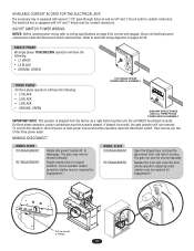
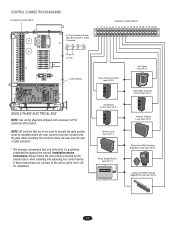
... (N.O.) Obstruction While Closing Edge/Photo Eye Input (N.O.) 17 Installation device instructions: Always follow the UL guidelines presented throughout the manual. If these instructions are to be installed where the user cannot come into contact with accessory kit for assistance. CONTROL CONNECTION... 20 24 Vac Control Board SINGLE PHASE ELECTRICAL BOX NOTE: See wiring diagrams shipped with the gate while operating the controls where the user has full view of gate operation. * We strongly recommend that you follow the instructions provided by the manufacturer when installing and...
... (N.O.) Obstruction While Closing Edge/Photo Eye Input (N.O.) 17 Installation device instructions: Always follow the UL guidelines presented throughout the manual. If these instructions are to be installed where the user cannot come into contact with accessory kit for assistance. CONTROL CONNECTION... 20 24 Vac Control Board SINGLE PHASE ELECTRICAL BOX NOTE: See wiring diagrams shipped with the gate while operating the controls where the user has full view of gate operation. * We strongly recommend that you follow the instructions provided by the manufacturer when installing and...
SL595 Manual
Page 18
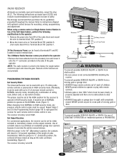
...recommend that you follow the UL guidelines presented throughout the manual. Refer to the operator: 1. When using a remote control or Single Button ...the radio continues transmitting (Figure 2). Repeat Steps 2 door. The LiftMaster Radio Receiver comes pre-wired to 15 rolling code • ALWAYS keep gate or garage door in the Programming Section (page 19) to ...reprogram the receiver for 1/4 second regardless of the length of the gate operator. AVERTISSEMENT remote controls or passwords in HIGH security mode. operate in HIGH security mode. It must be seen clearly, is ...
...recommend that you follow the UL guidelines presented throughout the manual. Refer to the operator: 1. When using a remote control or Single Button ...the radio continues transmitting (Figure 2). Repeat Steps 2 door. The LiftMaster Radio Receiver comes pre-wired to 15 rolling code • ALWAYS keep gate or garage door in the Programming Section (page 19) to ...reprogram the receiver for 1/4 second regardless of the length of the gate operator. AVERTISSEMENT remote controls or passwords in HIGH security mode. operate in HIGH security mode. It must be seen clearly, is ...

SL595 Manual
Page 23
.... 6. SAVE THESE INSTRUCTIONS. The gate MUST reverse on contact with gate controls. Limit switches may have to gate hardware. 7. Test the gate operator monthly. Use the emergency release ONLY when the gate is for wear or damage ADVERTENCIA X X NOTES 1. Severe or high cycle usage will require more frequent maintenance checks. 2. Read the owner's manual. ERTISSEMENT 4. NO ONE...
.... 6. SAVE THESE INSTRUCTIONS. The gate MUST reverse on contact with gate controls. Limit switches may have to gate hardware. 7. Test the gate operator monthly. Use the emergency release ONLY when the gate is for wear or damage ADVERTENCIA X X NOTES 1. Severe or high cycle usage will require more frequent maintenance checks. 2. Read the owner's manual. ERTISSEMENT 4. NO ONE...
SL595 Manual
Page 26
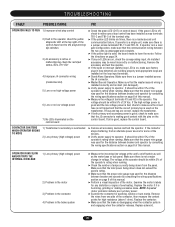
...units is undamaged and complete. ➤ If the yellow light is used for the distance between breaker and operator by consulting the wiring specifications section on page 8 of this manual. ➤ Perform a visual inspection of the motor. If the contactor stops chattering, find an alternate ...power source for any red LEDs are installed on control board. If operator is in a dual gate configuration, make sure the circuit fuse is...
...units is undamaged and complete. ➤ If the yellow light is used for the distance between breaker and operator by consulting the wiring specifications section on page 8 of this manual. ➤ Perform a visual inspection of the motor. If the contactor stops chattering, find an alternate ...power source for any red LEDs are installed on control board. If operator is in a dual gate configuration, make sure the circuit fuse is...
SL595 Manual
Page 27
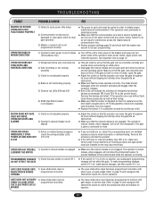
... swap any subsequent programming DO NOT EFFECT THE GATE changes will result in the on operator. 27 Remove the devices and retest. OPERATOR STOPS AND ALARMS 1) Clutch is not adjusted properly 2) Operator's manual release is not aligned ➤ Adjust the clutch so that the operator can move the gate throughout its travel without fault, check those accessories...
... swap any subsequent programming DO NOT EFFECT THE GATE changes will result in the on operator. 27 Remove the devices and retest. OPERATOR STOPS AND ALARMS 1) Clutch is not adjusted properly 2) Operator's manual release is not aligned ➤ Adjust the clutch so that the operator can move the gate throughout its travel without fault, check those accessories...
SL595 Manual
Page 33
...PARTS - Chain guide kit Optional diagonal brace kit 71-6532449 71-6532448 K50-18423 NOT SHOWN Heater kits (optional) 115/575V Operators Heater kits (optional) 208/230/460V Operators Replacement heater with : Alarm, spacer and faston. models SL585-150-11, SL585-150-21 10 23-3001 23-3005 VARIABLE ...PARTS On/off switch - 1 phase 115 208/230V On/off switch - 3 phase 01-34850 01-34850SP 01-34850FR NOT SHOWN Gate bracket Take up bolt Chain Bolt - 14" Owner's manual ...
...PARTS - Chain guide kit Optional diagonal brace kit 71-6532449 71-6532448 K50-18423 NOT SHOWN Heater kits (optional) 115/575V Operators Heater kits (optional) 208/230/460V Operators Replacement heater with : Alarm, spacer and faston. models SL585-150-11, SL585-150-21 10 23-3001 23-3005 VARIABLE ...PARTS On/off switch - 1 phase 115 208/230V On/off switch - 3 phase 01-34850 01-34850SP 01-34850FR NOT SHOWN Gate bracket Take up bolt Chain Bolt - 14" Owner's manual ...


