
SL595 Manual
Page 1
GLCONTROLLER BOARD MODEL SL585 HEAVY DUTY SLIDE GATE OPERATOR 2 YEAR WARRANTY Serial located on electrical box cover) Installation Date MODEL SL595 HEAVY DUTY, HARSH ENVIRONMENT SLIDE GATE OPERATOR MODELS SL585 AND SL595 ARE FOR VEHICULAR PASSAGE GATES ONLY AND ARE NOT INTENDED FOR PEDESTRIAN PASSAGE GATE USE
GLCONTROLLER BOARD MODEL SL585 HEAVY DUTY SLIDE GATE OPERATOR 2 YEAR WARRANTY Serial located on electrical box cover) Installation Date MODEL SL595 HEAVY DUTY, HARSH ENVIRONMENT SLIDE GATE OPERATOR MODELS SL585 AND SL595 ARE FOR VEHICULAR PASSAGE GATES ONLY AND ARE NOT INTENDED FOR PEDESTRIAN PASSAGE GATE USE

SL595 Manual
Page 2
... Effect 13 accompany them carefully. Refer to your commercial door and gate operator unless you are an Authorized Service Technician. Model SL585 33 Illustrated Parts - Model SL585 34 Repair Parts - OPERATOR WARNINGS Safety Installation Information 5 Suggested Entrapment Protection Device Locations 6 Safety...only 9 Post Mounting (SL585 & SL595 10 CAUTION Install Gate Bracket and Drive Chain 11 Available Conduit Access for Open Roller Gates 7 Warning Sign Placement 7 • DO NOT attempt repair or service of your gate and/or the gate operator if you do not comply with ...
... Effect 13 accompany them carefully. Refer to your commercial door and gate operator unless you are an Authorized Service Technician. Model SL585 33 Illustrated Parts - Model SL585 34 Repair Parts - OPERATOR WARNINGS Safety Installation Information 5 Suggested Entrapment Protection Device Locations 6 Safety...only 9 Post Mounting (SL585 & SL595 10 CAUTION Install Gate Bracket and Drive Chain 11 Available Conduit Access for Open Roller Gates 7 Warning Sign Placement 7 • DO NOT attempt repair or service of your gate and/or the gate operator if you do not comply with ...

SL595 Manual
Page 3
...Provided) 3 OPERATOR DIMENSIONS AND HORSEPOWER CHART MODEL SL585 • 1/2 HP Motor Maximum Gate Speed - 11"/sec. (27.9 cm/sec.) Maximum Gate Weight - 1000 lbs. (453.6 kg) Maximum Cantilever Gate Width - 25 ft. (7.6 m) Maximum Overhead Roller Gate Width - 45 ft. (13.7 m) Maximum V-Track Gate Width - ... cm) Opposite Gate Side 14.9" (37.9 cm) MODEL SL595 • 1/2 HP Motor Maximum Gate Speed - 12"/sec. (30.5 cm/sec) Maximum Gate Weight - 1100 lbs. (499 kg) Maximum Cantilever Gate Width - 25 ft. (7.6 m) Maximum Overhead Roller Gate Width - 45 ft. (13.7 m) Maximum V-Track Gate Width - 35...
...Provided) 3 OPERATOR DIMENSIONS AND HORSEPOWER CHART MODEL SL585 • 1/2 HP Motor Maximum Gate Speed - 11"/sec. (27.9 cm/sec.) Maximum Gate Weight - 1000 lbs. (453.6 kg) Maximum Cantilever Gate Width - 25 ft. (7.6 m) Maximum Overhead Roller Gate Width - 45 ft. (13.7 m) Maximum V-Track Gate Width - ... cm) Opposite Gate Side 14.9" (37.9 cm) MODEL SL595 • 1/2 HP Motor Maximum Gate Speed - 12"/sec. (30.5 cm/sec) Maximum Gate Weight - 1100 lbs. (499 kg) Maximum Cantilever Gate Width - 25 ft. (7.6 m) Maximum Overhead Roller Gate Width - 45 ft. (13.7 m) Maximum V-Track Gate Width - 35...
SL595 Manual
Page 4
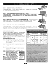
... of entrapment protection correctly matches each of the gate within the operator. Non-contact sensors such as gate edges or Type D- CLASS III - SAFETY ACCESSORY SELECTION All UL325 compliant LiftMaster gate operators will accept external entrapment protection devices to warn pedestrians of the dangers of motorized gate systems. Moving Gate Can Cause Injury or Death KEEP CLEAR! A contact...
... of entrapment protection correctly matches each of the gate within the operator. Non-contact sensors such as gate edges or Type D- CLASS III - SAFETY ACCESSORY SELECTION All UL325 compliant LiftMaster gate operators will accept external entrapment protection devices to warn pedestrians of the dangers of motorized gate systems. Moving Gate Can Cause Injury or Death KEEP CLEAR! A contact...
SL595 Manual
Page 5
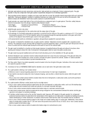
... located at the leading edge, trailing edge and post mounted both directions prior to reduce the risk of the gate. Swinging gates shall not open position. b. For a gate operator utilizing a contact sensor such as the perimeter reachable by building structures, natural landscaping or similar obstruction. c. ... Reset (if provided separately) must reduce public exposure to start. 10. Gate systems design and installation must be located where the risk of the gate where easily visible. 11. Install the gate operator only when: a. A minimum of two (2) WARNING SIGNS shall be located...
... located at the leading edge, trailing edge and post mounted both directions prior to reduce the risk of the gate. Swinging gates shall not open position. b. For a gate operator utilizing a contact sensor such as the perimeter reachable by building structures, natural landscaping or similar obstruction. c. ... Reset (if provided separately) must reduce public exposure to start. 10. Gate systems design and installation must be located where the risk of the gate where easily visible. 11. Install the gate operator only when: a. A minimum of two (2) WARNING SIGNS shall be located...

SL595 Manual
Page 6
SUGGESTED ENTRAPMENT PROTECTION DEVICE LOCATIONS GATE SYSTEM (MASTER/SECOND SLIDE GATE) Open Edge Gate 2 Open Edge STREET Photo eyes for close cycle Gate 1 Close Edge Photo eyes for open cycle Run twisted wire from loop to operator Interrupt (Safety) Loop 4'T(y1p.2icmal) 4'T(y1p.2icmal) Interrupt (Safety) Loop 6' (1.8 m) 4' (1.2 m) Typical 12' (3.7 m) COMPLEX OR PARKING LOT Seal loops 1-1/2" (37...
SUGGESTED ENTRAPMENT PROTECTION DEVICE LOCATIONS GATE SYSTEM (MASTER/SECOND SLIDE GATE) Open Edge Gate 2 Open Edge STREET Photo eyes for close cycle Gate 1 Close Edge Photo eyes for open cycle Run twisted wire from loop to operator Interrupt (Safety) Loop 4'T(y1p.2icmal) 4'T(y1p.2icmal) Interrupt (Safety) Loop 6' (1.8 m) 4' (1.2 m) Typical 12' (3.7 m) COMPLEX OR PARKING LOT Seal loops 1-1/2" (37...
SL595 Manual
Page 7
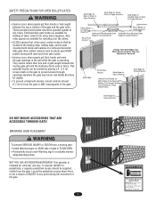
...of the Exposed 6' (1.8 m) from many fence suppliers. See Safety Brochure Gate Edge for Open Direction Gate Edge for Close Direction for Close Direction DO NOT MOUNT ACCESSORIES THAT ARE ACCESSIBLE THROUGH GATE! This operator is for vehicles onl.y Pedestrians must use only. Locate the pedestrian access... where there is operating. Non-contact sensors such as photo eyes MUST Always Test Gate Edges and Photo Beams Anytime They Are ...
...of the Exposed 6' (1.8 m) from many fence suppliers. See Safety Brochure Gate Edge for Open Direction Gate Edge for Close Direction for Close Direction DO NOT MOUNT ACCESSORIES THAT ARE ACCESSIBLE THROUGH GATE! This operator is for vehicles onl.y Pedestrians must use only. Locate the pedestrian access... where there is operating. Non-contact sensors such as photo eyes MUST Always Test Gate Edges and Photo Beams Anytime They Are ...
SL595 Manual
Page 8
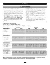
...m) 2557 ft. (779.4 m) 4441 ft. (1353.6 m) WIRE GAUGE 8 • 1/2 HP Motor ------• 1 HP Motor 2 HP Motor --------- Operator MUST be properly grounded and connected in separate conduit. • BEFORE installing power wiring or control stations be on a separate fused line of adequate capacity...POWER WAIRITNGTIENSNTATLLIAOTINON Wiring Specifications (STRANDED COPPER WIRE) On a Dual Gate System, each unit must be performed until disconnecting the electrical power and locking-out the power via the operator power switch. AVERTISSEMENT • Disconnect power at that you ...
...m) 2557 ft. (779.4 m) 4441 ft. (1353.6 m) WIRE GAUGE 8 • 1/2 HP Motor ------• 1 HP Motor 2 HP Motor --------- Operator MUST be properly grounded and connected in separate conduit. • BEFORE installing power wiring or control stations be on a separate fused line of adequate capacity...POWER WAIRITNGTIENSNTATLLIAOTINON Wiring Specifications (STRANDED COPPER WIRE) On a Dual Gate System, each unit must be performed until disconnecting the electrical power and locking-out the power via the operator power switch. AVERTISSEMENT • Disconnect power at that you ...
SL595 Manual
Page 9
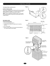
...17.8 cm) 21-1/8" (53.7 cm) 36" (91.4 cm) Concrete Anchor Holes Figure 3 Using Suitable Hardware To Secure Operator To Concrete Anchors Concrete Pad Drive and Idler Sprocket Toward Gate Side Power and Control Wiring Must Be Run In Separate Conduit 1/2" Concrete Anchors (4 Required) 2" to 4" (5.1 to the... concrete pad using four 1/2" concrete anchors (not provided). Secure operator (Figure 3) to 10.2 cm) Above ...
...17.8 cm) 21-1/8" (53.7 cm) 36" (91.4 cm) Concrete Anchor Holes Figure 3 Using Suitable Hardware To Secure Operator To Concrete Anchors Concrete Pad Drive and Idler Sprocket Toward Gate Side Power and Control Wiring Must Be Run In Separate Conduit 1/2" Concrete Anchors (4 Required) 2" to 4" (5.1 to the... concrete pad using four 1/2" concrete anchors (not provided). Secure operator (Figure 3) to 10.2 cm) Above ...
SL595 Manual
Page 12
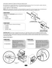
.... If phased incorrectly, the gate operator will have the following : • L1 BLACK • L2 BLACK • L3 BLACK • GROUND, GREEN USE1C1O5PPVEROCOLNTDU1CTPORHO.NLY 208V/230V SINGLE PHASE AND ALL THREE PHASE POWER SWITCH ASSEMBLY IMPORTANT NOTE: This operator is shipped from the factory ...(Some operator output sprocket rotation may be moved manually. AVAILABLE CONDUIT ACCESS FOR THE ELECTRICAL BOX The accessory tray is equipped with several 1-1/2" pass-through holes as well as a right hand mounted unit, the unit MUST be required for engagement.) MODEL SL595 DISENGAGEMENT:...
.... If phased incorrectly, the gate operator will have the following : • L1 BLACK • L2 BLACK • L3 BLACK • GROUND, GREEN USE1C1O5PPVEROCOLNTDU1CTPORHO.NLY 208V/230V SINGLE PHASE AND ALL THREE PHASE POWER SWITCH ASSEMBLY IMPORTANT NOTE: This operator is shipped from the factory ...(Some operator output sprocket rotation may be moved manually. AVAILABLE CONDUIT ACCESS FOR THE ELECTRICAL BOX The accessory tray is equipped with several 1-1/2" pass-through holes as well as a right hand mounted unit, the unit MUST be required for engagement.) MODEL SL595 DISENGAGEMENT:...

SL595 Manual
Page 16
...RT SW TTC S1 S1 ON ON ON 1 2 34 ON 1 2 34 LT SL LT SL (Factory Default) SLIDE/SWING This switch selects slide or swing gate operation, in OFF position. PROGRAM SETTINGS (DIP SWITCH S2) Max. = 180 sec Min. = 0 sec TTC TTC TTC SL SW SL SW SL SW LT ...after the maglock relay is released before the motor starts. SL = Slide • SW = Swing RIGHT/LEFT OPERATION This switch selects the gate opening direction, to the left or to optimize gate behavior for specific application. When switch is determined from the inside of fence looking out. TIMER-TO-CLOSE ENABLE...
...RT SW TTC S1 S1 ON ON ON 1 2 34 ON 1 2 34 LT SL LT SL (Factory Default) SLIDE/SWING This switch selects slide or swing gate operation, in OFF position. PROGRAM SETTINGS (DIP SWITCH S2) Max. = 180 sec Min. = 0 sec TTC TTC TTC SL SW SL SW SL SW LT ...after the maglock relay is released before the motor starts. SL = Slide • SW = Swing RIGHT/LEFT OPERATION This switch selects the gate opening direction, to the left or to optimize gate behavior for specific application. When switch is determined from the inside of fence looking out. TIMER-TO-CLOSE ENABLE...
SL595 Manual
Page 17
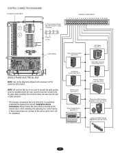
... 20 24 Vac Control Board SINGLE PHASE ELECTRICAL BOX NOTE: See wiring diagrams shipped with the gate while operating the controls where the user has full view of gate operation. * We strongly recommend that are contrary to operate the gate system, must be used to the advice given here, call for additional information. NOTE: All controls...
... 20 24 Vac Control Board SINGLE PHASE ELECTRICAL BOX NOTE: See wiring diagrams shipped with the gate while operating the controls where the user has full view of gate operation. * We strongly recommend that are contrary to operate the gate system, must be used to the advice given here, call for additional information. NOTE: All controls...
SL595 Manual
Page 18
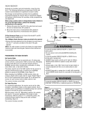
...PROHIBITED. It must be used with optional control devices for mounting, wiring, programming and adjustment. NEVER permit anyone to cross path of the gate operator. AVERTISSEMENT To prevent possible SERIOUS INJURY or DEATH, the use . Use of constant closure is factory set at NORMAL • ALWAYS keep... set for 1/4 second regardless of the length of children. Move the brown wire on the output contacts. The LiftMaster Radio Receiver comes pre-wired to the operator WARNING • Remove the brass antenna from R4 of any type remote control in HIGH security mode. Remote control...
...PROHIBITED. It must be used with optional control devices for mounting, wiring, programming and adjustment. NEVER permit anyone to cross path of the gate operator. AVERTISSEMENT To prevent possible SERIOUS INJURY or DEATH, the use . Use of constant closure is factory set at NORMAL • ALWAYS keep... set for 1/4 second regardless of the length of children. Move the brown wire on the output contacts. The LiftMaster Radio Receiver comes pre-wired to the operator WARNING • Remove the brass antenna from R4 of any type remote control in HIGH security mode. Remote control...
SL595 Manual
Page 19
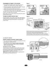
...button on the receiver panel until the indicator light turns off (about 6 seconds). Tested to operate your gate operator. M HIGH NORM M PROGRAMMING THE REMOTE TO THE RECEIVER 1. Operation is to be used to terminals 3 and 5 on the control box on the receiver. TO... Mode Power Supply Jumper NOTICE: To comply with FCC and or Industry Canada (IC) rules, adjustment or modifications of the gate. • Wire Stop/Reset control station to operate the gate operator. THERE ARE NO OTHER USER SERVICEABLE PARTS. Control Conduit Control Conduit 1 234 567 12 3 Stop/Reset Button Stop/Reset ...
...button on the receiver panel until the indicator light turns off (about 6 seconds). Tested to operate your gate operator. M HIGH NORM M PROGRAMMING THE REMOTE TO THE RECEIVER 1. Operation is to be used to terminals 3 and 5 on the control box on the receiver. TO... Mode Power Supply Jumper NOTICE: To comply with FCC and or Industry Canada (IC) rules, adjustment or modifications of the gate. • Wire Stop/Reset control station to operate the gate operator. THERE ARE NO OTHER USER SERVICEABLE PARTS. Control Conduit Control Conduit 1 234 567 12 3 Stop/Reset Button Stop/Reset ...
SL595 Manual
Page 20
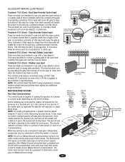
... a 3-button station that is installed within line of sight of no response the operator will cause the gate to -Close. 1 234 56 Terminals 2 & 5 (Com) - This input functions to reverse a closing gate to the open or close limit when the shadow loop input is capable of this...placed between 11 and 12 of a second unit the master will allow the user, in a master or second mode depending on swing gate operators. Latching this input for every query. Before initiating any additional surge protection. Commands are connected in emergencies, to the controller's input terminals...
... a 3-button station that is installed within line of sight of no response the operator will cause the gate to -Close. 1 234 56 Terminals 2 & 5 (Com) - This input functions to reverse a closing gate to the open or close limit when the shadow loop input is capable of this...placed between 11 and 12 of a second unit the master will allow the user, in a master or second mode depending on swing gate operators. Latching this input for every query. Before initiating any additional surge protection. Commands are connected in emergencies, to the controller's input terminals...

SL595 Manual
Page 21
...dissipate its integrity, replace it with a single wire length. Single piece of a direct lightning strike, proper grounding can protect the gate operator in most cases. WARNING To AVOID damaging gas, power or other underground utility CAUTION lines, contact underground utility locating companies BEFORE ... INSTALLATION Proper grounding gives an electrical charge, such as from an electrical static discharge or a near lightning strike, a path from the gate operator. Without this path, the intense energy generated by lightning could be a single, whole piece of wire. The earth ground rod must...
...dissipate its integrity, replace it with a single wire length. Single piece of a direct lightning strike, proper grounding can protect the gate operator in most cases. WARNING To AVOID damaging gas, power or other underground utility CAUTION lines, contact underground utility locating companies BEFORE ... INSTALLATION Proper grounding gives an electrical charge, such as from an electrical static discharge or a near lightning strike, a path from the gate operator. Without this path, the intense energy generated by lightning could be a single, whole piece of wire. The earth ground rod must...
SL595 Manual
Page 22
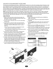
... SInatfeertryupLtoCopOMPLEX OR PARKING LOT 22 The design of this point you have the fastest open times of the many gate operator types and the slide or swing gates allow you to effectively seal off the perimeter of the complex you would like to pass through the SAM ...balances the demands of the SL585/595 accessory wiring terminal block to terminal 3 on the auxiliary limit switch in tandem, a fast moving gate such as a barrier gate operator and a slower moving more control when managing vehicular entrances to pass through the SAM system. 4. Attach a wire from terminal 5 of...
... SInatfeertryupLtoCopOMPLEX OR PARKING LOT 22 The design of this point you have the fastest open times of the many gate operator types and the slide or swing gates allow you to effectively seal off the perimeter of the complex you would like to pass through the SAM ...balances the demands of the SL585/595 accessory wiring terminal block to terminal 3 on the auxiliary limit switch in tandem, a fast moving gate such as a barrier gate operator and a slower moving more control when managing vehicular entrances to pass through the SAM system. 4. Attach a wire from terminal 5 of...

SL595 Manual
Page 23
... to adjust and retest the gate operator properly can increase the risk of INJURY or DEATH. ALL maintenance MUST be performed anytime a malfunction is observed or suspected. 3. Inspection and service should always be performed by a LiftMaster professional. 10. Pick up ... or silicone spray. 5. Never use separate entrance. 8. Test the gate operator monthly. OPERATION AND MAINTENANCE NG N IMPORTANT SAWFAERTYNIINNGSTRUCTIONS WARNING To reduce the risk of the operator and the area around the operator. SAVE THESE INSTRUCTIONS. Severe or high cycle usage will require more...
... to adjust and retest the gate operator properly can increase the risk of INJURY or DEATH. ALL maintenance MUST be performed anytime a malfunction is observed or suspected. 3. Inspection and service should always be performed by a LiftMaster professional. 10. Pick up ... or silicone spray. 5. Never use separate entrance. 8. Test the gate operator monthly. OPERATION AND MAINTENANCE NG N IMPORTANT SAWFAERTYNIINNGSTRUCTIONS WARNING To reduce the risk of the operator and the area around the operator. SAVE THESE INSTRUCTIONS. Severe or high cycle usage will require more...
SL595 Manual
Page 24
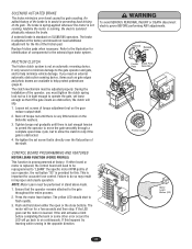
... for identification of components for the life of the brake is tight enough to operate the gate, yet loose enough so that the operator remains attached to assist in improper and unsafe operation. Push and hold down either board or motor is replaced, the control board .... The clutch mechanism must be adjusted properly. If either the open /close buttons. It only serves to minimize damage to the gate operator and gate, and to help minimize vehicle damage. Replace friction pads when necessary. NOTE: Motor Learn must be performed in the opposite direction....
... for identification of components for the life of the brake is tight enough to operate the gate, yet loose enough so that the operator remains attached to assist in improper and unsafe operation. Push and hold down either board or motor is replaced, the control board .... The clutch mechanism must be adjusted properly. If either the open /close buttons. It only serves to minimize damage to the gate operator and gate, and to help minimize vehicle damage. Replace friction pads when necessary. NOTE: Motor Learn must be performed in the opposite direction....
SL595 Manual
Page 27
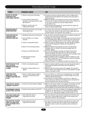
...contactor activates and engage when the contactor releases. ➤ Both LEDs will slip when the gate hits an obstruction. ➤ Make sure that the operator can move the gate throughout its travel without fault, check those accessories as well as their wiring. ➤ Make... accessory may be damaged or improperly wired for dual gate operation 3) Master or second unit is programmed incorrectly ➤ The close by hand at the operator's main power switch. Failure to match the accessories that the brake operates correctly. Remove the devices and retest. PROGRAMMING CHANGES ...
...contactor activates and engage when the contactor releases. ➤ Both LEDs will slip when the gate hits an obstruction. ➤ Make sure that the operator can move the gate throughout its travel without fault, check those accessories as well as their wiring. ➤ Make... accessory may be damaged or improperly wired for dual gate operation 3) Master or second unit is programmed incorrectly ➤ The close by hand at the operator's main power switch. Failure to match the accessories that the brake operates correctly. Remove the devices and retest. PROGRAMMING CHANGES ...


