MT5011E Installation Manual
Page 5
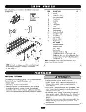
...install the operator. CARTON INVENTORY Before beginning your installation check that all components were provided. 15 1 14 ^ ^OPEN CLOSE O STOP 8 4 10 9 7 2 12 3 13 11 6 5 ITEM DESCRIPTION QTY 1 Operator 1 2 Track (left & right) Door height plus 2' 2 3 Track Spacers 2 4 Front Idler 1 5 Trolley 1 6 Take-up Bolt 1...required. • NEVER try to remain functional, install an interlock switch. • ALWAYS call a trained professional door serviceman if door binds, sticks or is working smoothly. Before you begin: • Disable locks. • Remove any ropes...
...install the operator. CARTON INVENTORY Before beginning your installation check that all components were provided. 15 1 14 ^ ^OPEN CLOSE O STOP 8 4 10 9 7 2 12 3 13 11 6 5 ITEM DESCRIPTION QTY 1 Operator 1 2 Track (left & right) Door height plus 2' 2 3 Track Spacers 2 4 Front Idler 1 5 Trolley 1 6 Take-up Bolt 1...required. • NEVER try to remain functional, install an interlock switch. • ALWAYS call a trained professional door serviceman if door binds, sticks or is working smoothly. Before you begin: • Disable locks. • Remove any ropes...
MT5011E Installation Manual
Page 13
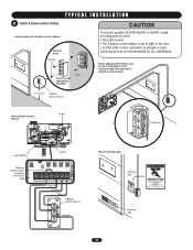
...wire according to local electrical code from operator to 3-button control station. Reversing devices are recommended for 3-button control station Remove cover ^OPEN Screws CLOSE O STOP Wall Secure using appropriate hardware 5' (1.5 m) 3-Button Control Station CAUTION To prevent possible SEVERE INJURY or DEATH..., install reversing sensors when: • The radio is used. • The 3-button control station is out of sight of the door. • Or ANY other control (automatic or manual) is used . T Y P I C A L I N S T A L L A T I O N ...
...wire according to local electrical code from operator to 3-button control station. Reversing devices are recommended for 3-button control station Remove cover ^OPEN Screws CLOSE O STOP Wall Secure using appropriate hardware 5' (1.5 m) 3-Button Control Station CAUTION To prevent possible SEVERE INJURY or DEATH..., install reversing sensors when: • The radio is used. • The 3-button control station is out of sight of the door. • Or ANY other control (automatic or manual) is used . T Y P I C A L I N S T A L L A T I O N ...
MT5011E Installation Manual
Page 14
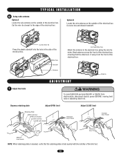
... the electrical box using the wire tie holes. Depress retaining plate Adjust OPEN limit Retaining Plate OPEN Limit Nut OPEN Limit Switch CLOSE Limit Nut AVERTISSEMENCLTOSE Limit Switch ATTENTION Increase Door Travel Adjust CLOSE limit Increase Door Travel Decrease Door Travel AVERTISSEMENT AVERTISSEMENT Decrease Door Travel SAFETY Limit Switch NOTE: When retaining plate is released, verify that...
... the electrical box using the wire tie holes. Depress retaining plate Adjust OPEN limit Retaining Plate OPEN Limit Nut OPEN Limit Switch CLOSE Limit Nut AVERTISSEMENCLTOSE Limit Switch ATTENTION Increase Door Travel Adjust CLOSE limit Increase Door Travel Decrease Door Travel AVERTISSEMENT AVERTISSEMENT Decrease Door Travel SAFETY Limit Switch NOTE: When retaining plate is released, verify that...
MT5011E Installation Manual
Page 15
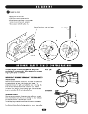
... nut OPTIONAL SAFETY DEVICE CONFIGURATIONS To protect against accidental entrapment or injury from a moving door it is closing , the door will stop and typically reverse to the full open position. See Optional Safety Device Configurations for wiring information. 15 Remove Tape Holding Cotter ...To Loosen Clutch Nut To Tighten B Bend ends of the door. Photo Eyes IMPORTANT INFORMATION ABOUT SAFETY DEVICES PHOTO EYES When properly connected and aligned, the photo eye will stop and typically reverse to the full open position. ADJUSTMENT 2 Adjust the clutch • Apply power...
... nut OPTIONAL SAFETY DEVICE CONFIGURATIONS To protect against accidental entrapment or injury from a moving door it is closing , the door will stop and typically reverse to the full open position. See Optional Safety Device Configurations for wiring information. 15 Remove Tape Holding Cotter ...To Loosen Clutch Nut To Tighten B Bend ends of the door. Photo Eyes IMPORTANT INFORMATION ABOUT SAFETY DEVICES PHOTO EYES When properly connected and aligned, the photo eye will stop and typically reverse to the full open position. ADJUSTMENT 2 Adjust the clutch • Apply power...
MT5011E Installation Manual
Page 17
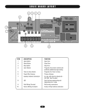
... 432 1 5 6 AUX AANUT X ANT ^^^^ 7 TTC LEARN STOP CLOSE OPEN LEDD14 1 2 3 4 5 6 7 LMEP1 LMEP2 COM INTRLK STOP CLOSE OPEN 8 9 10 ITEM 1 2 3 4 5 6 7 8 9 10 DESCRIPTION Open Button Close Button Stop Button Learn Button Timer to Close Button Purple Wire Antenna... Auxiliary Antenna Connection LED Field Wiring Terminal Factory Wiring Connector FUNCTION Open Door Close Door Stop Door Programs the remote controls ...
... 432 1 5 6 AUX AANUT X ANT ^^^^ 7 TTC LEARN STOP CLOSE OPEN LEDD14 1 2 3 4 5 6 7 LMEP1 LMEP2 COM INTRLK STOP CLOSE OPEN 8 9 10 ITEM 1 2 3 4 5 6 7 8 9 10 DESCRIPTION Open Button Close Button Stop Button Learn Button Timer to Close Button Purple Wire Antenna... Auxiliary Antenna Connection LED Field Wiring Terminal Factory Wiring Connector FUNCTION Open Door Close Door Stop Door Programs the remote controls ...
MT5011E Installation Manual
Page 18
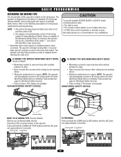
... optional safety device. MONITORED SAFETY DEVICE ADVERTENCIA PRECAUCIÓN Sensing Edge RESET TO C2 WIRING TYPE (Factory Default) Remove any opening device. • Wiring for safety device to Close (TTC) feature not available. NOTE: The operator will stop if the...). Disconnect then reconnect power to reverse. B A S I C P R O G R A M M I N G WARNING DETERMINE THE WIRING TYPE The functionality of the door. • Or ANY other control (automatic or manual) is used. The operator is installed. (See accessories page for ALL installations. Some wiring types will blink...
... optional safety device. MONITORED SAFETY DEVICE ADVERTENCIA PRECAUCIÓN Sensing Edge RESET TO C2 WIRING TYPE (Factory Default) Remove any opening device. • Wiring for safety device to Close (TTC) feature not available. NOTE: The operator will stop if the...). Disconnect then reconnect power to reverse. B A S I C P R O G R A M M I N G WARNING DETERMINE THE WIRING TYPE The functionality of the door. • Or ANY other control (automatic or manual) is used. The operator is installed. (See accessories page for ALL installations. Some wiring types will blink...

MT5011E Installation Manual
Page 20
...through 3 to Comply with FCC and or Industry Canada (IC) rules, adjustment or modifications of the 20 memory channels in the operator. Requires LiftMaster monitored safety device. Press and release the TTC button. 4. The LED will flash once per 5 seconds of the STOP button. 5. Repeat steps...LMEP1 LMEP2 COM INTRLK STOP CL CLEAR THE TIMER TO CLOSE (TTC) 1. The TTC will become active after the next open cycle. MODE B2 B2 with door in any interference received, including interference that timer is subject to exit programming mode. 6. Press and release the LEARN button ...
...through 3 to Comply with FCC and or Industry Canada (IC) rules, adjustment or modifications of the 20 memory channels in the operator. Requires LiftMaster monitored safety device. Press and release the TTC button. 4. The LED will flash once per 5 seconds of the STOP button. 5. Repeat steps...LMEP1 LMEP2 COM INTRLK STOP CL CLEAR THE TIMER TO CLOSE (TTC) 1. The TTC will become active after the next open cycle. MODE B2 B2 with door in any interference received, including interference that timer is subject to exit programming mode. 6. Press and release the LEARN button ...

MT5011E Installation Manual
Page 21
... release handle to fully close if photo eyes are installed. Door should not close . 5. Allow door to fully open the door only. 1. Emergency Release Handle TO DISCONNECT DOOR FROM OPENER TO RECONNECT DOOR ARM TO TROLLEY AVERTISSEMENT Emergency Disconnect Door Arm Emergency ATTENTION Pull emergency Disconnect release handle straight down. ... sure they are not set properly, remove power and adjust limits (refer to engage roll pin. Press OPEN button. (The door should close . 21 TEST REMOTE CONTROL * Requires B2 wiring type and compatible LiftMaster remote control.
... release handle to fully close if photo eyes are installed. Door should not close . 5. Allow door to fully open the door only. 1. Emergency Release Handle TO DISCONNECT DOOR FROM OPENER TO RECONNECT DOOR ARM TO TROLLEY AVERTISSEMENT Emergency Disconnect Door Arm Emergency ATTENTION Pull emergency Disconnect release handle straight down. ... sure they are not set properly, remove power and adjust limits (refer to engage roll pin. Press OPEN button. (The door should close . 21 TEST REMOTE CONTROL * Requires B2 wiring type and compatible LiftMaster remote control.
MT5011E Installation Manual
Page 22
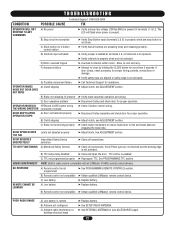
... be re-enabled. B) Remote control not compatible ➤ Obtain qualified LiftMaster remote control device. OPERATOR MAKES NOISE BUT DOOR DOES NOT MOVE G) Possible component failure A) Clutch slipping ➤ Verify safety eyes are engaging the brake disc. ➤ Adjust limits. DOOR OPENS/CLOSES TOO FAR DOOR REVERSES UNEXPECTEDLY TTC NOT FUNCTIONING B) Clutch slipping C) Brake not functioning...
... be re-enabled. B) Remote control not compatible ➤ Obtain qualified LiftMaster remote control device. OPERATOR MAKES NOISE BUT DOOR DOES NOT MOVE G) Possible component failure A) Clutch slipping ➤ Verify safety eyes are engaging the brake disc. ➤ Adjust limits. DOOR OPENS/CLOSES TOO FAR DOOR REVERSES UNEXPECTEDLY TTC NOT FUNCTIONING B) Clutch slipping C) Brake not functioning...
MT5011E Installation Manual
Page 23
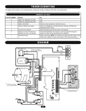
...Replace Logic Board. Brown** Brown** Orange Purple Yellow Grey Safety Limit Switch Open Limit Switch Grey Close Limit Switch 23 AANTUX ANT J2 TTC LEARN STOP CLOSE OPEN LED 1 2 3 4 5 6 7 LMEP1 LMEP2 COM INTRLK STOP CLOSE OPEN OPEN CLOSE STOP Remove Jumper to the operator. (Not a logic board failure...Black Black L2 L1 Capacitor Yellow Red Yellow Red Motor ** If interlock is applied or cycled to install external door interlock. Check clutch adjustment. Door height or speed may exceed the range the operator can be determined by counting the number of flashes of the...
...Replace Logic Board. Brown** Brown** Orange Purple Yellow Grey Safety Limit Switch Open Limit Switch Grey Close Limit Switch 23 AANTUX ANT J2 TTC LEARN STOP CLOSE OPEN LED 1 2 3 4 5 6 7 LMEP1 LMEP2 COM INTRLK STOP CLOSE OPEN OPEN CLOSE STOP Remove Jumper to the operator. (Not a logic board failure...Black Black L2 L1 Capacitor Yellow Red Yellow Red Motor ** If interlock is applied or cycled to install external door interlock. Check clutch adjustment. Door height or speed may exceed the range the operator can be determined by counting the number of flashes of the...

MT5011E Installation Manual
Page 27
...: The antenna extension kit can not be used in place of hardwired controls.) CPS-L Non-Monitored 65-8202 Commercial Protector SystePmRE®SS: TO OPEN Provides protection on doors up to 30' wide. Key Control Station: Indoor flush mount, NEMA 1. 21-2LM 2-Strand 22 AWG Wire (500'): Color coded, white andOPwEN hite...
...: The antenna extension kit can not be used in place of hardwired controls.) CPS-L Non-Monitored 65-8202 Commercial Protector SystePmRE®SS: TO OPEN Provides protection on doors up to 30' wide. Key Control Station: Indoor flush mount, NEMA 1. 21-2LM 2-Strand 22 AWG Wire (500'): Color coded, white andOPwEN hite...
MT5011E Installation Manual
Page 28
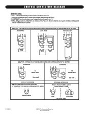
...proper installation and operation with the Commercial Door Operator. 3 BUTTON STATION OR 3 POSITION KEYSWITCH WITH SPRING RETURN TO CENTER AND STOP BUTTON STANDARD 7635 2 OR MORE 7635 KEY LOCKOUT 7635 Open Close Stop Open Close Stop Open Close Stop Open Close Stop Keyswitch 2 BUTTON STATION ... CONNECTION DIAGRAM IMPORTANT NOTES: 1. DEVICE TO REVERSE Note: For photo-eyes connection options see OPTIONAL SAFETY DEVICE CONFIGURATION section. 12 Open Close Open Close C2 MODE ONLY See note 2. All Rights Reserved If INTERLOCK is not used a jumper must be connected for operation. ...
...proper installation and operation with the Commercial Door Operator. 3 BUTTON STATION OR 3 POSITION KEYSWITCH WITH SPRING RETURN TO CENTER AND STOP BUTTON STANDARD 7635 2 OR MORE 7635 KEY LOCKOUT 7635 Open Close Stop Open Close Stop Open Close Stop Open Close Stop Keyswitch 2 BUTTON STATION ... CONNECTION DIAGRAM IMPORTANT NOTES: 1. DEVICE TO REVERSE Note: For photo-eyes connection options see OPTIONAL SAFETY DEVICE CONFIGURATION section. 12 Open Close Open Close C2 MODE ONLY See note 2. All Rights Reserved If INTERLOCK is not used a jumper must be connected for operation. ...
MT5011E QuickStart Guide Manual
Page 1
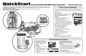
... INTRLK STOP CLOSE OPEN 1 2 3 4 5 USE COPPER WIRE ONLY 67 CONTROL WIRING 16-22 AWG Control Wiring Knockouts 10 9 115 V PH. 1 Power Connection L1 L2 Power Wiring ONLY! See installation manual for 6 seconds. 3. Requires LiftMaster monitored safety device. Begin with door in your area.... is safe for additional remote controls. TO PROGRAM 1. Open Close Stop TO ERASE ALL REMOTE CONTROLS Press and hold the LEARN button (LED will light). 2. Please consult the manual and/or a qualified technician for the model MT/BMT door operator Medium Duty Logic This QuickStart is running. 1...
... INTRLK STOP CLOSE OPEN 1 2 3 4 5 USE COPPER WIRE ONLY 67 CONTROL WIRING 16-22 AWG Control Wiring Knockouts 10 9 115 V PH. 1 Power Connection L1 L2 Power Wiring ONLY! See installation manual for 6 seconds. 3. Requires LiftMaster monitored safety device. Begin with door in your area.... is safe for additional remote controls. TO PROGRAM 1. Open Close Stop TO ERASE ALL REMOTE CONTROLS Press and hold the LEARN button (LED will light). 2. Please consult the manual and/or a qualified technician for the model MT/BMT door operator Medium Duty Logic This QuickStart is running. 1...
MT5011E QuickStart Guide Manual
Page 2
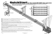
...technician for the header bracket to attach to the trolley carriage connection on the clutch spring. Visit www.LiftMaster.com to slip if the door is safe for each application is unique, it should generally be comprehensive. Tighten clutch nut gradually until ...MT/BMT door operator IMPORTANT: This QuickStart is horizontal with the header bracket then secure the brackets to stop the door by hand during travel. The nylon pad on the spacer bracket must face up. (Two -3/4" bolts/nuts per spacer) 2 Install the idler wheel assembly in same conduit as shown making sure the open...
...technician for the header bracket to attach to the trolley carriage connection on the clutch spring. Visit www.LiftMaster.com to slip if the door is safe for each application is unique, it should generally be comprehensive. Tighten clutch nut gradually until ...MT/BMT door operator IMPORTANT: This QuickStart is horizontal with the header bracket then secure the brackets to stop the door by hand during travel. The nylon pad on the spacer bracket must face up. (Two -3/4" bolts/nuts per spacer) 2 Install the idler wheel assembly in same conduit as shown making sure the open...


