
MT5011E Installation Manual
Page 2
... electric shock. Read them . TABLE OF CONTENTS SAFETY INFORMATION 2 APPLICATION 3 OPERATOR DIMENSIONS 4 OPERATOR SPECIFICATIONS 4 CARTON INVENTORY 5 PREPARATION 5 ASSEMBLY 6-8 TYPICAL INSTALLATION 9-14 ADJUSTMENT 14-15 OPTIONAL SAFETY DEVICE CONFIGURATIONS 15-16 LOGIC BOARD LAYOUT 17 BASIC PROGRAMMING 18-20 TESTING 21 MANUAL DISCONNECT 21 TROUBLESHOOTING 22-23 DIAGRAM 23 REPAIR PARTS 24-26 ACCESSORIES 27 CONTROL CONNECTIONS BACK COVER SAFETY INFORMATION WWAARRNNIINNGG Mechanical CAWUATIRONNING Electrical When you see this manual and follow all safety instructions...
... electric shock. Read them . TABLE OF CONTENTS SAFETY INFORMATION 2 APPLICATION 3 OPERATOR DIMENSIONS 4 OPERATOR SPECIFICATIONS 4 CARTON INVENTORY 5 PREPARATION 5 ASSEMBLY 6-8 TYPICAL INSTALLATION 9-14 ADJUSTMENT 14-15 OPTIONAL SAFETY DEVICE CONFIGURATIONS 15-16 LOGIC BOARD LAYOUT 17 BASIC PROGRAMMING 18-20 TESTING 21 MANUAL DISCONNECT 21 TROUBLESHOOTING 22-23 DIAGRAM 23 REPAIR PARTS 24-26 ACCESSORIES 27 CONTROL CONNECTIONS BACK COVER SAFETY INFORMATION WWAARRNNIINNGG Mechanical CAWUATIRONNING Electrical When you see this manual and follow all safety instructions...
MT5011E Installation Manual
Page 3
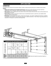
... wiring types will exceed door height by the manufacturer. • Radio receiver: A factory installed radio receiver allows remote controls, keyless entries and other remote command devices to be programmed to the operator. • Timer To Close: The Timer To Close feature allows the door to Basic Programming Section for descriptions of reliable and safe operation. SQUARE STANDARD SECTIONAL FEET MAXIMUM DOOR AREA AND MAXIMUM DOOR HEIGHT 14' --- 24 ga. 22 ga. Steel --- Features: • Supports...
... wiring types will exceed door height by the manufacturer. • Radio receiver: A factory installed radio receiver allows remote controls, keyless entries and other remote command devices to be programmed to the operator. • Timer To Close: The Timer To Close feature allows the door to Basic Programming Section for descriptions of reliable and safe operation. SQUARE STANDARD SECTIONAL FEET MAXIMUM DOOR AREA AND MAXIMUM DOOR HEIGHT 14' --- 24 ga. 22 ga. Steel --- Features: • Supports...
MT5011E Installation Manual
Page 4
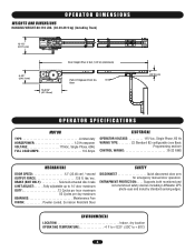
... maximum 50 Cycles per day maximum BEARINGS Maintenance Free FINISH Powder coated, Corrosion Resistant Steel SAFETY DISCONNECT Quick disconnect door arm for emergency manual door operation. BRAKE (BMT ONLY Solenoid actuated disc brake LIMIT ADJUST:. . . . . .Fully adjustable up to + 50˚C) 4 Supports both monitored and non-monitored safety devices including LiftMaster CPS photo-eyes and industry standard sensing edges. ENTRAPMENT PROTECTION: . . . . OPERATOR DIMENSIONS WEIGHTS AND DIMENSIONS HANGING WEIGHT...
... maximum 50 Cycles per day maximum BEARINGS Maintenance Free FINISH Powder coated, Corrosion Resistant Steel SAFETY DISCONNECT Quick disconnect door arm for emergency manual door operation. BRAKE (BMT ONLY Solenoid actuated disc brake LIMIT ADJUST:. . . . . .Fully adjustable up to + 50˚C) 4 Supports both monitored and non-monitored safety devices including LiftMaster CPS photo-eyes and industry standard sensing edges. ENTRAPMENT PROTECTION: . . . . OPERATOR DIMENSIONS WEIGHTS AND DIMENSIONS HANGING WEIGHT...
MT5011E Installation Manual
Page 5
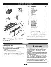
...components were provided. 15 1 14 ^ ^OPEN CLOSE O STOP 8 4 10 9 7 2 12 3 13 11 6 5 ITEM DESCRIPTION QTY 1 Operator 1 2 Track (left & right) Door height plus 2' 2 3 Track Spacers 2 4 Front Idler 1 5 Trolley 1 6 Take-up Bolt 1 7 Chain 1 8 Master Links 2 9 Header Bracket 1 10 Header Pivot Shaft 1 11 Curved Door Arm 1 12 Straight Arm 1 13 Door Bracket 1 14 3-Button Station 1 15 Warning Sign 2 NOT SHOWN Installation Manual 1 Quickstart Guide 1 User's Guide 1 Caution Label 1 Installation Hardware Bag 1 Complete with: Bolts 3/8"-16...
...components were provided. 15 1 14 ^ ^OPEN CLOSE O STOP 8 4 10 9 7 2 12 3 13 11 6 5 ITEM DESCRIPTION QTY 1 Operator 1 2 Track (left & right) Door height plus 2' 2 3 Track Spacers 2 4 Front Idler 1 5 Trolley 1 6 Take-up Bolt 1 7 Chain 1 8 Master Links 2 9 Header Bracket 1 10 Header Pivot Shaft 1 11 Curved Door Arm 1 12 Straight Arm 1 13 Door Bracket 1 14 3-Button Station 1 15 Warning Sign 2 NOT SHOWN Installation Manual 1 Quickstart Guide 1 User's Guide 1 Caution Label 1 Installation Hardware Bag 1 Complete with: Bolts 3/8"-16...

MT5011E Installation Manual
Page 9
... the header wall and the ceiling. Extension springs require center mounting. 1 Mark the center of the door Mark the center line of Door Travel 9 Extend the line on torsion spring doors. Level (Optional) 2 Determine and mark the highest point of door travel Level Header Wall High Point of the door. TYPICAL INSTALLATION DETERMINE HEADER BRACKET MOUNTING LOCATION The trolley operator is generally mounted over the center of door stile / top section support.
... the header wall and the ceiling. Extension springs require center mounting. 1 Mark the center of the door Mark the center line of Door Travel 9 Extend the line on torsion spring doors. Level (Optional) 2 Determine and mark the highest point of door travel Level Header Wall High Point of the door. TYPICAL INSTALLATION DETERMINE HEADER BRACKET MOUNTING LOCATION The trolley operator is generally mounted over the center of door stile / top section support.
MT5011E Installation Manual
Page 11
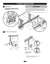
...: Refer to structural supports of the garage. T Y P I C A L I N S T A L L A T I O N WARNING 6 Hang the operator Secure the operator using appropriate fasteners and locking hardware that will support the weight of Door PRECAUCIÓNVertical Door Door Bracket Use appropriate hardware to secure door bracket to door (Not Provided). Concrete anchors MUST be used if installing ANY brackets into masonry. Lock Nut Washer Bolt (Not Provided) Bolt (Not Provided) 7 Attach door arm to trolley and door AVERTISSEMENT Bolt Nut (Not...
...: Refer to structural supports of the garage. T Y P I C A L I N S T A L L A T I O N WARNING 6 Hang the operator Secure the operator using appropriate fasteners and locking hardware that will support the weight of Door PRECAUCIÓNVertical Door Door Bracket Use appropriate hardware to secure door bracket to door (Not Provided). Concrete anchors MUST be used if installing ANY brackets into masonry. Lock Nut Washer Bolt (Not Provided) Bolt (Not Provided) 7 Attach door arm to trolley and door AVERTISSEMENT Bolt Nut (Not...
MT5011E Installation Manual
Page 12
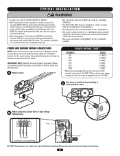
...' 6 AWG* 4 AWG* 2 AWG* 8 Remove cover * Maximum wire gauge that time the unit may be returned to the operator or in separate conduit. Upon completion of maintenance the area MUST be cleared and secured, at the fuse box BEFORE proceeding. Must use 14 AWG or heavier wire for wiring as DISTANCE 50' indicated on a separate fused line of adequate capacity. • ALL electrical connections MUST be made...
...' 6 AWG* 4 AWG* 2 AWG* 8 Remove cover * Maximum wire gauge that time the unit may be returned to the operator or in separate conduit. Upon completion of maintenance the area MUST be cleared and secured, at the fuse box BEFORE proceeding. Must use 14 AWG or heavier wire for wiring as DISTANCE 50' indicated on a separate fused line of adequate capacity. • ALL electrical connections MUST be made...
MT5011E Installation Manual
Page 14
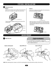
... B Locate the wire antenna on the outside of the electrical box. Antenna WARNING 1 CAdAjusUt thTe lIimOitsN ADJUSTMENT WARNING WARNING To avoid SERIOUS personal INJURY or DEATH from the front of the electrical box. Depress retaining plate Adjust OPEN limit Retaining Plate OPEN Limit Nut OPEN Limit Switch CLOSE Limit Nut AVERTISSEMENCLTOSE Limit Switch ATTENTION Increase Door Travel Adjust CLOSE limit Increase Door Travel Decrease Door Travel AVERTISSEMENT AVERTISSEMENT Decrease Door Travel SAFETY Limit Switch NOTE: When retaining plate is released, verify that the antenna is...
... B Locate the wire antenna on the outside of the electrical box. Antenna WARNING 1 CAdAjusUt thTe lIimOitsN ADJUSTMENT WARNING WARNING To avoid SERIOUS personal INJURY or DEATH from the front of the electrical box. Depress retaining plate Adjust OPEN limit Retaining Plate OPEN Limit Nut OPEN Limit Switch CLOSE Limit Nut AVERTISSEMENCLTOSE Limit Switch ATTENTION Increase Door Travel Adjust CLOSE limit Increase Door Travel Decrease Door Travel AVERTISSEMENT AVERTISSEMENT Decrease Door Travel SAFETY Limit Switch NOTE: When retaining plate is released, verify that the antenna is...
MT5011E Installation Manual
Page 15
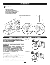
... other across the door, no more than 6" (15 cm) above the floor. Photo Eyes IMPORTANT INFORMATION ABOUT SAFETY DEVICES PHOTO EYES When properly connected and aligned, the photo eye will stop and typically reverse to the full open position. The sensing edge must be installed on the bottom of its invisible light beam. See Optional Safety Device Configurations for wiring information. 15 Remove Tape Holding Cotter Pin to Spring Insert Cotterpin Clutch...
... other across the door, no more than 6" (15 cm) above the floor. Photo Eyes IMPORTANT INFORMATION ABOUT SAFETY DEVICES PHOTO EYES When properly connected and aligned, the photo eye will stop and typically reverse to the full open position. The sensing edge must be installed on the bottom of its invisible light beam. See Optional Safety Device Configurations for wiring information. 15 Remove Tape Holding Cotter Pin to Spring Insert Cotterpin Clutch...
MT5011E Installation Manual
Page 16
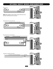
...) 4-wire electric sensing edge (White) TTC ^^^^ 1 LEARN STOP CLOSE OPEN LEDD14 2 3 4 LMEP1 LMEP2 COM INTRLK STOP CLOSE OPEN 5 6 7 AUX ANT AUX ANT TTC ^^^^ 1 LEARN STOP CLOSE OPEN LEDD14 2 3 4 LMEP1 LMEP2 COM INTRLK STOP CLOSE OPEN 2-Wire electric or pneumatic sensing edge 2-wire electric or pneumatic sensing edge (White/Black) (White) 16 5 6 7 ANT X ANT TTC ^^^^ 1 LEARN STOP CLOSE OPEN LEDD14 2 3 45 LMEP1 LMEP2 COM INTRLK STOP CLOSE OPEN 67 OPTIONAL SAFETY DEVICE CONFIGURATIONS CPS Photo-Eyes (White) (White/Black) NOTE: When installing model...
...) 4-wire electric sensing edge (White) TTC ^^^^ 1 LEARN STOP CLOSE OPEN LEDD14 2 3 4 LMEP1 LMEP2 COM INTRLK STOP CLOSE OPEN 5 6 7 AUX ANT AUX ANT TTC ^^^^ 1 LEARN STOP CLOSE OPEN LEDD14 2 3 4 LMEP1 LMEP2 COM INTRLK STOP CLOSE OPEN 2-Wire electric or pneumatic sensing edge 2-wire electric or pneumatic sensing edge (White/Black) (White) 16 5 6 7 ANT X ANT TTC ^^^^ 1 LEARN STOP CLOSE OPEN LEDD14 2 3 45 LMEP1 LMEP2 COM INTRLK STOP CLOSE OPEN 67 OPTIONAL SAFETY DEVICE CONFIGURATIONS CPS Photo-Eyes (White) (White/Black) NOTE: When installing model...
MT5011E Installation Manual
Page 17
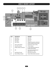
...codes Field wiring connections Factory wiring harness connection 17 LOGIC BOARD LAYOUT 432 1 5 6 AUX AANUT X ANT ^^^^ 7 TTC LEARN STOP CLOSE OPEN LEDD14 1 2 3 4 5 6 7 LMEP1 LMEP2 COM INTRLK STOP CLOSE OPEN 8 9 10 ITEM 1 2 3 4 5 6 7 8 9 10 DESCRIPTION Open Button Close Button Stop Button Learn Button Timer to Close Button Purple Wire Antenna Auxiliary Antenna Connection LED Field Wiring Terminal Factory Wiring Connector FUNCTION Open Door Close Door Stop Door Programs the remote controls and performs additional programming Programs the Timer to Close Primary Antenna For use...
...codes Field wiring connections Factory wiring harness connection 17 LOGIC BOARD LAYOUT 432 1 5 6 AUX AANUT X ANT ^^^^ 7 TTC LEARN STOP CLOSE OPEN LEDD14 1 2 3 4 5 6 7 LMEP1 LMEP2 COM INTRLK STOP CLOSE OPEN 8 9 10 ITEM 1 2 3 4 5 6 7 8 9 10 DESCRIPTION Open Button Close Button Stop Button Learn Button Timer to Close Button Purple Wire Antenna Auxiliary Antenna Connection LED Field Wiring Terminal Factory Wiring Connector FUNCTION Open Door Close Door Stop Door Programs the remote controls and performs additional programming Programs the Timer to Close Primary Antenna For use...
MT5011E Installation Manual
Page 18
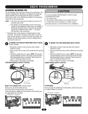
... used. The LED on the wiring type. C2 WIRING TYPE WITHOUT MONITORED SAFETY DEVICE A (Factory Default) • Momentary contact to open and stop if the pressure to the operator. Electrical Box Logic Board Photo Eye TO PROGRAM Press and hold the LEARN and STOP buttons until the LED goes out (approximately 3 seconds). NON-MONITORED SAFETY DEVICE CAUTION To prevent possible SEVERE INJURY or DEATH, install reversing sensors when: • The radio is used. • The 3-button control...
... used. The LED on the wiring type. C2 WIRING TYPE WITHOUT MONITORED SAFETY DEVICE A (Factory Default) • Momentary contact to open and stop if the pressure to the operator. Electrical Box Logic Board Photo Eye TO PROGRAM Press and hold the LEARN and STOP buttons until the LED goes out (approximately 3 seconds). NON-MONITORED SAFETY DEVICE CAUTION To prevent possible SEVERE INJURY or DEATH, install reversing sensors when: • The radio is used. • The 3-button control...

MT5011E Installation Manual
Page 19
... Monitored Safety Devices) • Timer to reverse. NOTE: The operator will automatically convert to B2 wiring when Monitored Safety Device is installed. (See accessories page for safety device to Close (TTC) feature not available. Electrical Box Logic Board NO PROGRAMMING REQUIRED 014A1030 J4 C32 TP1 C20 R25 C9 C21 U1 D7 D5 U4 D6 D4 C31 AAUUX AANNTT J2 L5 ^^^^ R27 TTC 1 C18 D14 LEARN STOP CLOSE OPEN LED...
... Monitored Safety Devices) • Timer to reverse. NOTE: The operator will automatically convert to B2 wiring when Monitored Safety Device is installed. (See accessories page for safety device to Close (TTC) feature not available. Electrical Box Logic Board NO PROGRAMMING REQUIRED 014A1030 J4 C32 TP1 C20 R25 C9 C21 U1 D7 D5 U4 D6 D4 C31 AAUUX AANNTT J2 L5 ^^^^ R27 TTC 1 C18 D14 LEARN STOP CLOSE OPEN LED...

MT5011E Installation Manual
Page 20
... USER SERVICEABLE PARTS. Example: 30 second TTC = 6 presses of timer setting. Press and release the LEARN button. 2. Press and release the LEARN button (LED will light). 2. TTC will use 3 of the remote control until the LED flashes rapidly, then release to complete programming (LED will become enabled after a preset time, adjustable from 5 to 60 seconds. Press and release the LEARN button (LED will light.) 2. Press and hold the LEARN button (LED will go out). 3. Press and hold the button on the logic board (OPEN, CLOSE or STOP). TIMER...
... USER SERVICEABLE PARTS. Example: 30 second TTC = 6 presses of timer setting. Press and release the LEARN button. 2. Press and release the LEARN button (LED will light). 2. TTC will use 3 of the remote control until the LED flashes rapidly, then release to complete programming (LED will become enabled after a preset time, adjustable from 5 to 60 seconds. Press and release the LEARN button (LED will light.) 2. Press and hold the LEARN button (LED will go out). 3. Press and hold the button on the logic board (OPEN, CLOSE or STOP). TIMER...

MT5011E Installation Manual
Page 21
... to obstruction and reverse if sensing edge is CLOSED. Release CLOSE button. Press OPEN button. (The door should close . 21 Open the door. 2. Emergency disconnect will close to the Adjustment section for operation of the photo eyes or sensing edge. 3. TAESVT E3-BRUTTTIOSNSCOENMTREOLNSTTATION 1. The door AVERTISSEMENT should open . Press remote control button. 2. Press CLOSE button. Test all safety instructions included in an open . TEST THE SAFETY DEVICES (IF INSTALLED) 1. Door Arm Lift free end of door arm to disengage trolley ONLY when door is installed. 4.
... to obstruction and reverse if sensing edge is CLOSED. Release CLOSE button. Press OPEN button. (The door should close . 21 Open the door. 2. Emergency disconnect will close to the Adjustment section for operation of the photo eyes or sensing edge. 3. TAESVT E3-BRUTTTIOSNSCOENMTREOLNSTTATION 1. The door AVERTISSEMENT should open . Press remote control button. 2. Press CLOSE button. Test all safety instructions included in an open . TEST THE SAFETY DEVICES (IF INSTALLED) 1. Door Arm Lift free end of door arm to disengage trolley ONLY when door is installed. 4.
MT5011E Installation Manual
Page 22
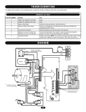
...LiftMaster remote control device. ➤ Replace battery. ➤ Replace battery. POOR RADIO RANGE A) Low battery in radio receiver compatible with all connections. If door closes, check accessory for proper operation. B) Brake not releasing (if present) C) Door operation problem OPERATOR MOVES IN OPEN and CLOSE button wiring THE WRONG DIRECTION connection reversed DOOR DRIFTS AFTER OPERATOR STOPS A) Door not balanced properly ➤ Verify brake assembly operation and wiring. ➤ Disconnect trolley and check door for proper operation. ➤ Check 3-button control wiring...
...LiftMaster remote control device. ➤ Replace battery. ➤ Replace battery. POOR RADIO RANGE A) Low battery in radio receiver compatible with all connections. If door closes, check accessory for proper operation. B) Brake not releasing (if present) C) Door operation problem OPERATOR MOVES IN OPEN and CLOSE button wiring THE WRONG DIRECTION connection reversed DOOR DRIFTS AFTER OPERATOR STOPS A) Door not balanced properly ➤ Verify brake assembly operation and wiring. ➤ Disconnect trolley and check door for proper operation. ➤ Check 3-button control wiring...
MT5011E Installation Manual
Page 23
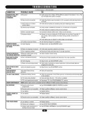
... is not used, wires are capped together. Check clutch adjustment. Reverse the yellow and red motor wires on the logic board. # OF LED FLASHES 1 2 3 4 5 6 7 DIAGNOSTIC LED TABLE STATUS System OK. Replace Logic Board. NOTE: It is normal for the logic board LED to flash 7 times when power is applied or cycled to install external door interlock. Operating in B2 mode Stuck CLOSE button Monitored Safety Device failure Incorrect motor direction Maximum run timer has timed out (Maximum run time = 90 seconds) Logic Board Failure FIX none...
... is not used, wires are capped together. Check clutch adjustment. Reverse the yellow and red motor wires on the logic board. # OF LED FLASHES 1 2 3 4 5 6 7 DIAGNOSTIC LED TABLE STATUS System OK. Replace Logic Board. NOTE: It is normal for the logic board LED to flash 7 times when power is applied or cycled to install external door interlock. Operating in B2 mode Stuck CLOSE button Monitored Safety Device failure Incorrect motor direction Maximum run timer has timed out (Maximum run time = 90 seconds) Logic Board Failure FIX none...
MT5011E Installation Manual
Page 24
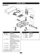
..., depress plate, limit switches (3), standoffs, screws and locknuts. K2 K72-12493 Limit Switch Kit Complete with : Limit shaft, limit nuts, limit bearings, limit sprocket, washers, compression ring, roll pin and e-ring. K3 K94-33961 Wiring Harness Assembly Complete with: harness and wire ties K4 K1A6424-2 Logic Board Assembly, Medium Duty "E", 315 MHz K4 K1A6424-3 Logic Board Assembly, Medium Duty "E", 390 MHz K5 K74-31243 MOV assembly * To order complete electrical box kit, add a (K-) prefix to the model number for the operator.
..., depress plate, limit switches (3), standoffs, screws and locknuts. K2 K72-12493 Limit Switch Kit Complete with : Limit shaft, limit nuts, limit bearings, limit sprocket, washers, compression ring, roll pin and e-ring. K3 K94-33961 Wiring Harness Assembly Complete with: harness and wire ties K4 K1A6424-2 Logic Board Assembly, Medium Duty "E", 315 MHz K4 K1A6424-3 Logic Board Assembly, Medium Duty "E", 390 MHz K5 K74-31243 MOV assembly * To order complete electrical box kit, add a (K-) prefix to the model number for the operator.
MT5011E QuickStart Guide Manual
Page 1
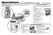
... TTC button (LED will flash once per 5 seconds of the 20 memory channels in your area. Programming Remote Controls 7 6 5 3 White/Black White LiftMaster® CPS Safety Sensors SINGLE BUTTON REMOTE CONTROL Built in 315 MHz radio receiver permits as many as 20 Security✚® remote controls or dip switch remote controls in fully closed position. 2. Repeat steps 1 and 2 for Professional Installation Only. Press and hold the LEARN button (LED will use . Release both buttons. 3. QuickStart for the model MT/BMT door operator Medium Duty Logic...
... TTC button (LED will flash once per 5 seconds of the 20 memory channels in your area. Programming Remote Controls 7 6 5 3 White/Black White LiftMaster® CPS Safety Sensors SINGLE BUTTON REMOTE CONTROL Built in 315 MHz radio receiver permits as many as 20 Security✚® remote controls or dip switch remote controls in fully closed position. 2. Repeat steps 1 and 2 for Professional Installation Only. Press and hold the LEARN button (LED will use . Release both buttons. 3. QuickStart for the model MT/BMT door operator Medium Duty Logic...
MT5011E QuickStart Guide Manual
Page 2
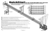
... intended use the pivot shaft and cotter pins to secure the track assembly to achieve proper adjustment. (Two nuts and a lock washer, two master links) 6 Provide a mounting pad for the model MT/BMT door operator IMPORTANT: This QuickStart is obstructed. Connect the take -up bolt will sag about 3" at the mid-point. Reinstall cotter pin when finished. 13 Additional programming and troubleshooting can pivot. These instructions are positioned between the limit switches...
... intended use the pivot shaft and cotter pins to secure the track assembly to achieve proper adjustment. (Two nuts and a lock washer, two master links) 6 Provide a mounting pad for the model MT/BMT door operator IMPORTANT: This QuickStart is obstructed. Connect the take -up bolt will sag about 3" at the mid-point. Reinstall cotter pin when finished. 13 Additional programming and troubleshooting can pivot. These instructions are positioned between the limit switches...


