Owners Manual
Page 4
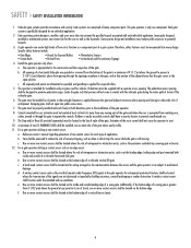
... and work freely in both inside and outside of entrapment or obstruction exists, such as an edge sensor: a. Reference owner's manual regarding placement of non-contact sensor for user activation must be located at least six feet (6') away from reaching over, under ...the line-of-sight of a gate system. A gate operator can create risks for an individual application. 2. Install the gate operator only when: a. All openings of a horizontal slide gate are not obstructed or impeded by a moving . f. A minimum of the gate where easily visible. 11. c. A wireless...
... and work freely in both inside and outside of entrapment or obstruction exists, such as an edge sensor: a. Reference owner's manual regarding placement of non-contact sensor for user activation must be located at least six feet (6') away from reaching over, under ...the line-of-sight of a gate system. A gate operator can create risks for an individual application. 2. Install the gate operator only when: a. All openings of a horizontal slide gate are not obstructed or impeded by a moving . f. A minimum of the gate where easily visible. 11. c. A wireless...
Owners Manual
Page 9
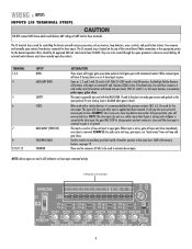
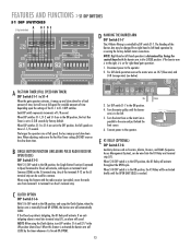
... strip is to make gate reverse and go back to the open position- All external control devices must have normally open with inputs on terminal 4 and Common (COM) on the control board C18 U18 C15 F MANUAL 1 2 3 4 5 6 7 8 9 1Ø 11 12 OPEN Q2 J5 S3 T2 T4 T6 T8 T1 T3 T5 T7 ...CLOSE OPEN 1 OPEN 2 OPEN 3 R21 AUX 4 SAFETY 5 CLOSE 6 BACK 7 SHADOW 8 C16 D15 D16 D17 D18 D19 D22 D23 D24 3 R24 R35 R41 R46 R5&#...
... strip is to make gate reverse and go back to the open position- All external control devices must have normally open with inputs on terminal 4 and Common (COM) on the control board C18 U18 C15 F MANUAL 1 2 3 4 5 6 7 8 9 1Ø 11 12 OPEN Q2 J5 S3 T2 T4 T6 T8 T1 T3 T5 T7 ...CLOSE OPEN 1 OPEN 2 OPEN 3 R21 AUX 4 SAFETY 5 CLOSE 6 BACK 7 SHADOW 8 C16 D15 D16 D17 D18 D19 D22 D23 D24 3 R24 R35 R41 R46 R5&#...
Owners Manual
Page 12
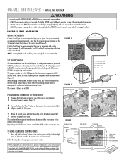
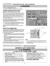
... code setting or replacing the battery. JJ55 FIGURE 1 C18 U18 C15 1 MANUAL 1 2 3 4 5 6 7 8 9 1Ø 11 12 UX LIMITS M/S J3 R14 Q2 OPEN J5 23 D1 456 R1Ø R9 R8 R7 R6 R5 R4 R3 D9... R2 C18 U18 C15 DJ121Ø 1 AUX LIMITS M/S J3 R14 S3 MANUAL R18 Q2 OPEN 1 2 3 4 5 6 7 8 9 1Ø 11 12 J5 T2 T1 T4 T3 T6 T5 T8 T7 78 D8...adjusted, and there are no obstructions to cross path of children. HIGH SECURITY MODE FIGURE 3 OPENING RECEIVER OPEN RECEIVER Connect Antenna 24V 12V NOTICE: To comply with up to the following two conditions: (1) ...
... code setting or replacing the battery. JJ55 FIGURE 1 C18 U18 C15 1 MANUAL 1 2 3 4 5 6 7 8 9 1Ø 11 12 UX LIMITS M/S J3 R14 Q2 OPEN J5 23 D1 456 R1Ø R9 R8 R7 R6 R5 R4 R3 D9... R2 C18 U18 C15 DJ121Ø 1 AUX LIMITS M/S J3 R14 S3 MANUAL R18 Q2 OPEN 1 2 3 4 5 6 7 8 9 1Ø 11 12 J5 T2 T1 T4 T3 T6 T5 T8 T7 78 D8...adjusted, and there are no obstructions to cross path of children. HIGH SECURITY MODE FIGURE 3 OPENING RECEIVER OPEN RECEIVER Connect Antenna 24V 12V NOTICE: To comply with up to the following two conditions: (1) ...
Owners Manual
Page 13
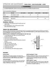
... and slow down time. When S1-8 DIP switch is in the ON position, and using the Clutch Option; If an antitailgating alarm is manually forced UP (OPEN), the barrier arm will automatically CLOSE. When adjusting, make sure the Fast Run Timer settings DO NOT overrun the slow down time. When ...parallel to the operator. 2. Disconnect power to the arm and just behind the limit sensor. 6. Connect power to the right, it is forced UP (OPEN). 13 If the Close Loop detects tailgating, the K1 Relay will activate, with the radio receiver (provided), move the radio wire from terminal 1 to terminal...
... and slow down time. When S1-8 DIP switch is in the ON position, and using the Clutch Option; If an antitailgating alarm is manually forced UP (OPEN), the barrier arm will automatically CLOSE. When adjusting, make sure the Fast Run Timer settings DO NOT overrun the slow down time. When ...parallel to the operator. 2. Disconnect power to the arm and just behind the limit sensor. 6. Connect power to the right, it is forced UP (OPEN). 13 If the Close Loop detects tailgating, the K1 Relay will activate, with the radio receiver (provided), move the radio wire from terminal 1 to terminal...
Owners Manual
Page 15
... D18 D19 1 1 J2 AUX LIMITS M/S U1 OLS D7 OPEN X1 D6 BRAKE D5 CLOSE D4 CLS D3 MANUAL 1234567 J3 R14 OPEN Q2 J5 S3 T2 T4 T6 T1 T3 T5 OPEN 1 OPEN 2 OPEN 3 AUX 4 SAFET C3 R24 R35 R41 R46 U6 IRD1 U7... and objects away from children. 6. NO ONE SHOULD CROSS THE PATH OF THE MOVING GATE. 4. WARNING After any adjustment open position, time out (using the time delay set at the limits: Move the limit cam closer to detect obstructions. Pedestrians... be required after the belt wears in order to the NOTES: control board by a LiftMaster professional. 10.
... D18 D19 1 1 J2 AUX LIMITS M/S U1 OLS D7 OPEN X1 D6 BRAKE D5 CLOSE D4 CLS D3 MANUAL 1234567 J3 R14 OPEN Q2 J5 S3 T2 T4 T6 T1 T3 T5 OPEN 1 OPEN 2 OPEN 3 AUX 4 SAFET C3 R24 R35 R41 R46 U6 IRD1 U7... and objects away from children. 6. NO ONE SHOULD CROSS THE PATH OF THE MOVING GATE. 4. WARNING After any adjustment open position, time out (using the time delay set at the limits: Move the limit cam closer to detect obstructions. Pedestrians... be required after the belt wears in order to the NOTES: control board by a LiftMaster professional. 10.
Owners Manual
Page 16
... bracket and pieces in pairs. Connect AC power and batteries. 10. BATTERY HANDLING / STORAGE Refer to OPEN on the Control Board Layout page). Turn the S3 Manual Open switch to the battery manufacturer's Material Safety Data Sheets (01-30839 "MSDS Sheets, Battery, Standard"). Reinstall... a hazardous waste and disposed of this document for wear and lubricate ● Battery Maintenance Replace batteries. ◆ Repeat ALL procedures. LiftMaster does not recommend storage of the pin. (Correct pin (P/N MA013) is required, DO NOT DAMAGE THE SHAFT, use . 16 BATTERY...
... bracket and pieces in pairs. Connect AC power and batteries. 10. BATTERY HANDLING / STORAGE Refer to OPEN on the Control Board Layout page). Turn the S3 Manual Open switch to the battery manufacturer's Material Safety Data Sheets (01-30839 "MSDS Sheets, Battery, Standard"). Reinstall... a hazardous waste and disposed of this document for wear and lubricate ● Battery Maintenance Replace batteries. ◆ Repeat ALL procedures. LiftMaster does not recommend storage of the pin. (Correct pin (P/N MA013) is required, DO NOT DAMAGE THE SHAFT, use . 16 BATTERY...
Owners Manual
Page 20
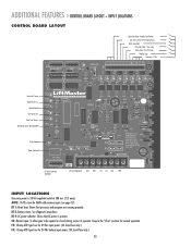
... to be opened or closed ...K1 Relay Terminals (Optional) ACC+ ACC- See diagnostic procedures. S3: Manual open. Keep in the "Close" position for 24 Vdc battery input power.... 0 Vdc C18 U18 C15 Q6 Q5 Q4 D28 Open Limit Sensor Open Drivers On Motor Brake On Close Drivers On Close Limit...R1 R12 R17 R16 MANUAL Q2 OPEN 1 2 3 4 5 6 7 8 9 1Ø 11 12 J5 S3 T2 T4 T6 T8 T1 T3 T5 T7 OPEN 1 OPEN 2 OPEN 3 AUX 4 SAFETY ... R33 R39 R44 R48 R59 C22 OPEN X1 D6 R1Ø R9 BRAKE...(see page 13). Reader, Push Button Aux Open / Reset (Pulse Open/Close) Safety Loop Input Close Gate Input - ...
... to be opened or closed ...K1 Relay Terminals (Optional) ACC+ ACC- See diagnostic procedures. S3: Manual open. Keep in the "Close" position for 24 Vdc battery input power.... 0 Vdc C18 U18 C15 Q6 Q5 Q4 D28 Open Limit Sensor Open Drivers On Motor Brake On Close Drivers On Close Limit...R1 R12 R17 R16 MANUAL Q2 OPEN 1 2 3 4 5 6 7 8 9 1Ø 11 12 J5 S3 T2 T4 T6 T8 T1 T3 T5 T7 OPEN 1 OPEN 2 OPEN 3 AUX 4 SAFETY ... R33 R39 R44 R48 R59 C22 OPEN X1 D6 R1Ø R9 BRAKE...(see page 13). Reader, Push Button Aux Open / Reset (Pulse Open/Close) Safety Loop Input Close Gate Input - ...
Quick Start Guide
Page 1
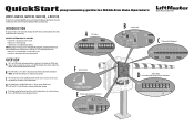
...facing the control board with devices wired into the J5 terminal strip. A DIP Switches ON ON S1 S2 1 2345678 1 2345678 OFF OFF B Manual Switch MANUAL OPEN S3 CLOSE J5 C J5 Terminal Strip (Wiring Inputs) 123456789 J5 F Limit Cam Position CAM POSITION E K1 Relay (optional) and Terminal Strip (... to -Close, Single Button Function, and Fail Safe (Auto Open on the J5 terminal strip. The DIP switch settings can be set to open only. • The barrier arm is set to the installation manual for complete information regarding installation and programming. D The J4 Motor...
...facing the control board with devices wired into the J5 terminal strip. A DIP Switches ON ON S1 S2 1 2345678 1 2345678 OFF OFF B Manual Switch MANUAL OPEN S3 CLOSE J5 C J5 Terminal Strip (Wiring Inputs) 123456789 J5 F Limit Cam Position CAM POSITION E K1 Relay (optional) and Terminal Strip (... to -Close, Single Button Function, and Fail Safe (Auto Open on the J5 terminal strip. The DIP switch settings can be set to open only. • The barrier arm is set to the installation manual for complete information regarding installation and programming. D The J4 Motor...
Quick Start Guide
Page 2
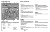
... K J5 Wiring Inputs L J5 Common (COM) Wiring Inputs M K1 Relay (optional) and Terminal Strip (J1) N Accessory Output Power (300 mA) max. When DIP switches S1-1 to the right, it is determined by factory default. NOTE: Right-hand or left -hand operation by reversing the ...slow down time. CONTROL BOARD LAYOUT A BCDE F GH I J K L 1 1 J2 AUX LIMITS M/S D8 S1 12 R1 R12 J3 R14 R16 MANUAL 1 2 3 4 5 6 7 8 9 1Ø 11 12 OPEN Q2 J5 S3 T2 T1 OPEN 1 OPEN 2 CLOSE R21 T4 T3 OPEN 3 AUX 4 T6 T8 T5 T7 SAFETY 5 CLOSE 6 BACK 7 SHADOW C16 C3 U4 C19 D15 D16 D17 D18 D19 D22...
... K J5 Wiring Inputs L J5 Common (COM) Wiring Inputs M K1 Relay (optional) and Terminal Strip (J1) N Accessory Output Power (300 mA) max. When DIP switches S1-1 to the right, it is determined by factory default. NOTE: Right-hand or left -hand operation by reversing the ...slow down time. CONTROL BOARD LAYOUT A BCDE F GH I J K L 1 1 J2 AUX LIMITS M/S D8 S1 12 R1 R12 J3 R14 R16 MANUAL 1 2 3 4 5 6 7 8 9 1Ø 11 12 OPEN Q2 J5 S3 T2 T1 OPEN 1 OPEN 2 CLOSE R21 T4 T3 OPEN 3 AUX 4 T6 T8 T5 T7 SAFETY 5 CLOSE 6 BACK 7 SHADOW C16 C3 U4 C19 D15 D16 D17 D18 D19 D22...


