LA500 Manual
Page 3
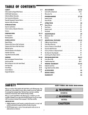
... 28 Reset Button 28 Remote Control 28 Party Mode 28 MAINTENANCE 29 Maintenance Chart 29 Batteries 29 ADDITIONAL FEATURES 29-35 LiftMaster Internet Gateway 29 Control Board Overview 30 Accessory Features on Control Board 31 Expansion Board Overview 32 Accessory Features on Expansion... Board 33 Gate Operator Setup Examples 34 Limit Setup with a Remote Control 35 TROUBLESHOOTING 36-41 Control Board LEDs 36-37 Troubleshooting Chart 38-41 WIRING DIAGRAMS 42-43 Standard Control Box 42 Large Metal Control Box (XLM 43 ACCESSORIES...
... 28 Reset Button 28 Remote Control 28 Party Mode 28 MAINTENANCE 29 Maintenance Chart 29 Batteries 29 ADDITIONAL FEATURES 29-35 LiftMaster Internet Gateway 29 Control Board Overview 30 Accessory Features on Control Board 31 Expansion Board Overview 32 Accessory Features on Expansion... Board 33 Gate Operator Setup Examples 34 Limit Setup with a Remote Control 35 TROUBLESHOOTING 36-41 Control Board LEDs 36-37 Troubleshooting Chart 38-41 WIRING DIAGRAMS 42-43 Standard Control Box 42 Large Metal Control Box (XLM 43 ACCESSORIES...
LA500 Manual
Page 9
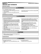
... devices to protect in accordance with a rigid object or reverse when an object activates the non-contact sensors. Pedestrians MUST use ONLY LiftMaster part 29-NP712 for vehicles ONLY. For continued protection against fire and electrocution: • DISCONNECT power (AC or solar and battery)... operator. NOTE: The operator should be properly grounded and connected in BOTH the open and close gate cycles. Read the owner's manual. TROUBLESHOOTING To protect against fire: • Replace ONLY with gate controls. NO ONE SHOULD CROSS THE PATH OF THE MOVING GATE. •...
... devices to protect in accordance with a rigid object or reverse when an object activates the non-contact sensors. Pedestrians MUST use ONLY LiftMaster part 29-NP712 for vehicles ONLY. For continued protection against fire and electrocution: • DISCONNECT power (AC or solar and battery)... operator. NOTE: The operator should be properly grounded and connected in BOTH the open and close gate cycles. Read the owner's manual. TROUBLESHOOTING To protect against fire: • Replace ONLY with gate controls. NO ONE SHOULD CROSS THE PATH OF THE MOVING GATE. •...
LA500 Manual
Page 32
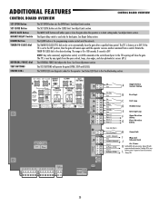
... YE BLU RED BR GRN WT YE BLU RED SOLAR / CHARGER + GROUND ID RESET ALARM 30 See Adjust Limits section. The TTC is in the Troubleshooting section. The TEST BUTTONS will either open controls, loops, close edges, and close the gate. See Adjust Limits section. See Bipart Delay section. NOTE: Any...
... YE BLU RED BR GRN WT YE BLU RED SOLAR / CHARGER + GROUND ID RESET ALARM 30 See Adjust Limits section. The TTC is in the Troubleshooting section. The TEST BUTTONS will either open controls, loops, close edges, and close the gate. See Adjust Limits section. See Bipart Delay section. NOTE: Any...
LA500 Manual
Page 38
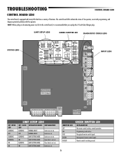
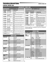
... Open limit is not set . Remote controls are set . The control board LEDs indicate the status of functions. INPUT LEDS -+ J5 N.O. Unrecognized remote control signal. TROUBLESHOOTING CONTROL BOARD LEDS CONTROL BOARD LEDS The control board is equipped with the operator. BLINKING LIMIT SETTING MODE Limits are set . BLINKING LIMIT SETTING MODE...
... Open limit is not set . Remote controls are set . The control board LEDs indicate the status of functions. INPUT LEDS -+ J5 N.O. Unrecognized remote control signal. TROUBLESHOOTING CONTROL BOARD LEDS CONTROL BOARD LEDS The control board is equipped with the operator. BLINKING LIMIT SETTING MODE Limits are set . BLINKING LIMIT SETTING MODE...
LA500 Manual
Page 39
... Check gate travel , if necessary adjust force setting Verify the release handle is engaged and locked BEFORE replacing the control board cycle the power first. TROUBLESHOOTING CONTROL BOARD LEDS CONTROL BOARD LEDS DIAGNOSTIC CODES LEDS YELLOW DIAGNOSTIC LED RED DIAGNOSTIC LED # BLINKS 1 BLINK 2 BLINKS MEANING Low Power Mode ID resistor failure...
... Check gate travel , if necessary adjust force setting Verify the release handle is engaged and locked BEFORE replacing the control board cycle the power first. TROUBLESHOOTING CONTROL BOARD LEDS CONTROL BOARD LEDS DIAGNOSTIC CODES LEDS YELLOW DIAGNOSTIC LED RED DIAGNOSTIC LED # BLINKS 1 BLINK 2 BLINKS MEANING Low Power Mode ID resistor failure...
LA500 Manual
Page 40
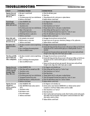
... for open or fully close when setting limits. Correct as needed . c) Disconnect arm from gate and move gate manually. Check other wireless controls or devices. TROUBLESHOOTING TROUBLESHOOTING CHART FAULT Operator does not run . Control board powers up, but cannot set correct limits. Repair gate as necessary. Check operator's antenna and antenna wire...
... for open or fully close when setting limits. Correct as needed . c) Disconnect arm from gate and move gate manually. Check other wireless controls or devices. TROUBLESHOOTING TROUBLESHOOTING CHART FAULT Operator does not run . Control board powers up, but cannot set correct limits. Repair gate as necessary. Check operator's antenna and antenna wire...
LA500 Manual
Page 41
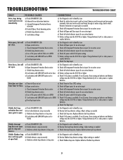
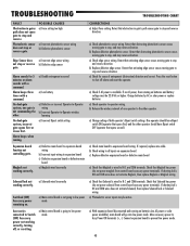
... voltage must be 22.0 Vdc or higher. c) Check Exit loop wire. d) Check if AC power is available. Adjust settings as needed c) Check Interrupt loop wire. TROUBLESHOOTING TROUBLESHOOTING CHART FAULT Gate stops during travel . Gate closes, but will not open. Vehicle Shadow loop does not keep gate at open . c) Check all Entrapment Protection...
... voltage must be 22.0 Vdc or higher. c) Check Exit loop wire. d) Check if AC power is available. Adjust settings as needed c) Check Interrupt loop wire. TROUBLESHOOTING TROUBLESHOOTING CHART FAULT Gate stops during travel . Gate closes, but will not open. Vehicle Shadow loop does not keep gate at open . c) Check all Entrapment Protection...
LA500 Manual
Page 42
... power maglock from control board accessory power terminals). Press the reset button to all inputs on expansion board. b) Check wiring to shut off , or resetting. TROUBLESHOOTING TROUBLESHOOTING CHART FAULT Obstruction in gate's path causes gate to low power mode. CORRECTIONS a) Adjust force setting. Retest that Solenoid is wired to the other . a) Check...
... power maglock from control board accessory power terminals). Press the reset button to all inputs on expansion board. b) Check wiring to shut off , or resetting. TROUBLESHOOTING TROUBLESHOOTING CHART FAULT Obstruction in gate's path causes gate to low power mode. CORRECTIONS a) Adjust force setting. Retest that Solenoid is wired to the other . a) Check...

LA500 Manual
Page 43
and COM. and COM or to another setting and test. If voltage is connected to either N.O. TROUBLESHOOTING TROUBLESHOOTING CHART FAULT Accessories connected to Accessory power not working correctly. Anti-Tailgating not working correctly, turning off, or resetting. AUX Relay not working correctly. POSSIBLE ...
and COM. and COM or to another setting and test. If voltage is connected to either N.O. TROUBLESHOOTING TROUBLESHOOTING CHART FAULT Accessories connected to Accessory power not working correctly. Anti-Tailgating not working correctly, turning off, or resetting. AUX Relay not working correctly. POSSIBLE ...

