
Solar Gate Access System Daily Cycle Chart Manual
Page 1
.... 800 lb. Snow, performance minimizing power consumption at all other times. and charge rate. LA500 Solar Gate Access System Daily Cycle Chart The LA500 Solar Gate Access System utilizes an Solar panel(s) must be located in an open area clear LAipnon4wo1ve2ar twiSvheoePnloanwereeGrdMeadatnmeaogAsetcmfocerneot spSeysrsatSteinmygstaotegdaemtleivewDrhaileily Cycle Chart of obstructions and shading for the entire day...
.... 800 lb. Snow, performance minimizing power consumption at all other times. and charge rate. LA500 Solar Gate Access System Daily Cycle Chart The LA500 Solar Gate Access System utilizes an Solar panel(s) must be located in an open area clear LAipnon4wo1ve2ar twiSvheoePnloanwereeGrdMeadatnmeaogAsetcmfocerneot spSeysrsatSteinmygstaotegdaemtleivewDrhaileily Cycle Chart of obstructions and shading for the entire day...
LA500 Manual
Page 4
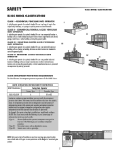
... means of gate travel. RESIDENTIAL VEHICULAR GATE OPERATOR A vehicular gate operator (or system) intended for use in which unauthorized access is installed on both the open and close directions of entrapment protection. COMMERCIAL/GENERAL ACCESS VEHICULAR GATE OPERATOR A vehicular gate operator (or system) intended for use in a commercial location or building...
... means of gate travel. RESIDENTIAL VEHICULAR GATE OPERATOR A vehicular gate operator (or system) intended for use in which unauthorized access is installed on both the open and close directions of entrapment protection. COMMERCIAL/GENERAL ACCESS VEHICULAR GATE OPERATOR A vehicular gate operator (or system) intended for use in a commercial location or building...
LA500 Manual
Page 5
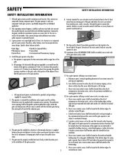
...work freely in the line-of-sight of entrapment. The gate must reduce public exposure to operate the controls. The pedestrian access opening and closing to mechanical damage. d. The gate must be designed to prevent unauthorized use conditions. One or more contact sensors shall...gates used for exposed rollers. 5. c. SAFETY SAFETY INSTALLATION INFORMATION 1. A wireless contact sensor shall function under , around or through the openings anywhere in the gate, and in that portion of the adjacent fence that persons will not come in contact with the vehicular gate ...
...work freely in the line-of-sight of entrapment. The gate must reduce public exposure to operate the controls. The pedestrian access opening and closing to mechanical damage. d. The gate must be designed to prevent unauthorized use conditions. One or more contact sensors shall...gates used for exposed rollers. 5. c. SAFETY SAFETY INSTALLATION INFORMATION 1. A wireless contact sensor shall function under , around or through the openings anywhere in the gate, and in that portion of the adjacent fence that persons will not come in contact with the vehicular gate ...
LA500 Manual
Page 6
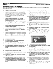
...vertically project no more than 6 feet (1.83 m) above grade. VEHICULAR HORIZONTAL SLIDE GATES fixed object when the gate moves toward the fully open position, subject to the provisions in the 4.1.1.1 and 4.1.1.2. 3.1 The following provisions shall apply to Class I, Class II and Class III ... 610-832-9585 or www.astm.org. 1. GENERAL REQUIREMENTS 3.1.3 A gap, measured in the horizontal plane parallel to the designed fully open and fully closed positions. A gate latch shall not be installed on an automatically operated gate. 3.1.5 All gates shall be designed with ...
...vertically project no more than 6 feet (1.83 m) above grade. VEHICULAR HORIZONTAL SLIDE GATES fixed object when the gate moves toward the fully open position, subject to the provisions in the 4.1.1.1 and 4.1.1.2. 3.1 The following provisions shall apply to Class I, Class II and Class III ... 610-832-9585 or www.astm.org. 1. GENERAL REQUIREMENTS 3.1.3 A gap, measured in the horizontal plane parallel to the designed fully open and fully closed positions. A gate latch shall not be installed on an automatically operated gate. 3.1.5 All gates shall be designed with ...
LA500 Manual
Page 7
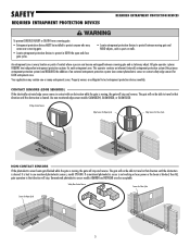
...are also acceptable. Use non monitored edge sensor models G65MG0204, G65MGR020, or G65MGS020. 3 Edge Contact Sensor Edge Sensor for Open Cycle Edge Sensor for each entrapment zone. All gate operator systems REQUIRE two independent entrapment protection systems for Close Cycle NON-... is every location or point of an external entrapment protection system (non-contact photoelectric sensor or contact safety edge sensor) for Open Cycle 5 SAFETY REQUIRED ENTRAPMENT PROTECTION DEVICES REQUIRED ENTRAPMENT PROTECTION DEVICES To prevent SERIOUS INJURY or DEATH from a moving gate: &#...
...are also acceptable. Use non monitored edge sensor models G65MG0204, G65MGR020, or G65MGS020. 3 Edge Contact Sensor Edge Sensor for Open Cycle Edge Sensor for each entrapment zone. All gate operator systems REQUIRE two independent entrapment protection systems for Close Cycle NON-... is every location or point of an external entrapment protection system (non-contact photoelectric sensor or contact safety edge sensor) for Open Cycle 5 SAFETY REQUIRED ENTRAPMENT PROTECTION DEVICES REQUIRED ENTRAPMENT PROTECTION DEVICES To prevent SERIOUS INJURY or DEATH from a moving gate: &#...

LA500 Manual
Page 8
... power wiring should be on the gate to protect between moving gate and RIGID objects, such as photo eyes MUST be mounted across the gate opening and operate during full movement of SEVERE INJURY or DEATH: • Without a properly installed safety reversal system, persons (particularly small children) could...; To AVOID damaging gas, power or other control may travel limits) is not a chance of INJURY at any point during BOTH the open and close cycles. • Entrapment protection devices MUST be installed to protect anyone who may be properly grounded and connected in BOTH the...
... power wiring should be on the gate to protect between moving gate and RIGID objects, such as photo eyes MUST be mounted across the gate opening and operate during full movement of SEVERE INJURY or DEATH: • Without a properly installed safety reversal system, persons (particularly small children) could...; To AVOID damaging gas, power or other control may travel limits) is not a chance of INJURY at any point during BOTH the open and close cycles. • Entrapment protection devices MUST be installed to protect anyone who may be properly grounded and connected in BOTH the...
LA500 Manual
Page 9
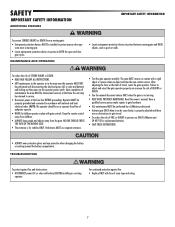
... • Test the gate operator monthly. NOTE: The operator should be on contact with fuse of FIRE or INJURY to protect in BOTH the open and close gate cycles. TROUBLESHOOTING To protect against fire: • Replace ONLY with a rigid object or reverse when an object activates the non-... are no obstructions to service. • Disconnect power at that time the unit may come near the operator MUST NOT be performed by a LiftMaster professional. • Activate gate ONLY when it can increase the risk of maintenance the area MUST be properly grounded and connected in the area ...
... • Test the gate operator monthly. NOTE: The operator should be on contact with fuse of FIRE or INJURY to protect in BOTH the open and close gate cycles. TROUBLESHOOTING To protect against fire: • Replace ONLY with a rigid object or reverse when an object activates the non-... are no obstructions to service. • Disconnect power at that time the unit may come near the operator MUST NOT be performed by a LiftMaster professional. • Activate gate ONLY when it can increase the risk of maintenance the area MUST be properly grounded and connected in the area ...
LA500 Manual
Page 10
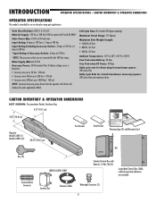
...CARTON INVENTORY & OPERATOR DIMENSIONS NOT SHOWN: Documentation Packet, Hardware Bag 4.21" (10.7 cm) 5.83" (14.8 cm) Operator Model LA500 (1) Model LA500-S (2) 40.35" (102.5 cm) Post Bracket Gate Bracket Warning Signs (2) and Warranty Card OR Key (2) Terminal Block Connector MODEL...Metal Control Box (XLM), ordered separately (batteries not included) Junction Box Extension Cable Watertight Connector (2) 8 Full Cycle Time: 32 seconds (90 degree opening) Maximum Travel Range: 115 degrees Maximum Gate Weight/Length: • 1600 lbs./8 foot • 800 lbs./16 foot • 600 lbs./...
...CARTON INVENTORY & OPERATOR DIMENSIONS NOT SHOWN: Documentation Packet, Hardware Bag 4.21" (10.7 cm) 5.83" (14.8 cm) Operator Model LA500 (1) Model LA500-S (2) 40.35" (102.5 cm) Post Bracket Gate Bracket Warning Signs (2) and Warranty Card OR Key (2) Terminal Block Connector MODEL...Metal Control Box (XLM), ordered separately (batteries not included) Junction Box Extension Cable Watertight Connector (2) 8 Full Cycle Time: 32 seconds (90 degree opening) Maximum Travel Range: 115 degrees Maximum Gate Weight/Length: • 1600 lbs./8 foot • 800 lbs./16 foot • 600 lbs./...
LA500 Manual
Page 11
... - EXIT, SHADOW, or INTERRUPT LOOP: accessory connection EXPANSION BOARD FEATURES • Plug-in Loop Detector Connectors (Model LOOPDETLM Loop Detector) - OPEN LIMIT: ON at either 310, 315, 390 MHz, or 433 MHz CONTROL BOARD FEATURES • Electronic Limit adjustment and control • Adjustable...extension antenna is optional) Large Metal Control Box (XLM) has external antenna. • Electronic limit adjustment and control from close limit switch - OPEN, CLOSE, or STOP: accessory connection and on-board button - SHADOW - POWER: ON with up to 50 remote controls and 2 keyless ...
... - EXIT, SHADOW, or INTERRUPT LOOP: accessory connection EXPANSION BOARD FEATURES • Plug-in Loop Detector Connectors (Model LOOPDETLM Loop Detector) - OPEN LIMIT: ON at either 310, 315, 390 MHz, or 433 MHz CONTROL BOARD FEATURES • Electronic Limit adjustment and control • Adjustable...extension antenna is optional) Large Metal Control Box (XLM) has external antenna. • Electronic limit adjustment and control from close limit switch - OPEN, CLOSE, or STOP: accessory connection and on-board button - SHADOW - POWER: ON with up to 50 remote controls and 2 keyless ...
LA500 Manual
Page 12
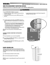
...) EARTH GROUND ROD Proper grounding gives an electrical charge, such as from an electrical static discharge or a near lightning strike, a path from which to stay open when vehicles are required to protect against any entrapment or safety conditions encountered in most cases. Gate must be constructed and installed according to ASTM...
...) EARTH GROUND ROD Proper grounding gives an electrical charge, such as from an electrical static discharge or a near lightning strike, a path from which to stay open when vehicles are required to protect against any entrapment or safety conditions encountered in most cases. Gate must be constructed and installed according to ASTM...
LA500 Manual
Page 13
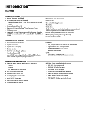
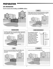
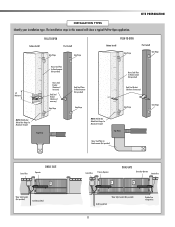
... ! Water Tight Conduit (Not provided) Earth Ground Rod Control Box Primary Operator ! INSTALLATION TYPES Identify your installation type. PULL-TO-OPEN Column Install Post Install Gate Hinge Gate Hinge PUSH-TO-OPEN Column Install Gate Hinge SITE PREPARATION Post Install Gate Hinge Heavy Steel Plate for Reinforcement (Not provided) 10" Minimum Heavy... if necessary) Gate Hinge NOTE: Weld Re Bar Behind Gate Hinges for Maximum Strength. The installation steps in this manual will show a typical Pull-to-Open application.
... ! Water Tight Conduit (Not provided) Earth Ground Rod Control Box Primary Operator ! INSTALLATION TYPES Identify your installation type. PULL-TO-OPEN Column Install Post Install Gate Hinge Gate Hinge PUSH-TO-OPEN Column Install Gate Hinge SITE PREPARATION Post Install Gate Hinge Heavy Steel Plate for Reinforcement (Not provided) 10" Minimum Heavy... if necessary) Gate Hinge NOTE: Weld Re Bar Behind Gate Hinges for Maximum Strength. The installation steps in this manual will show a typical Pull-to-Open application.
LA500 Manual
Page 15
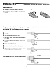
... the gate. 2 Choose a vertical mounting location for a Miracle-One™ operator, use the existing post bracket and gate bracket. PUSH-TO-OPEN 7.75" 8.5" 13 If this operator is Push-to-Open, refer to the illustration to mark the location of the first measurement. 5 Measure 8.5 inches from the brackets and proceed to page...
... the gate. 2 Choose a vertical mounting location for a Miracle-One™ operator, use the existing post bracket and gate bracket. PUSH-TO-OPEN 7.75" 8.5" 13 If this operator is Push-to-Open, refer to the illustration to mark the location of the first measurement. 5 Measure 8.5 inches from the brackets and proceed to page...
LA500 Manual
Page 17
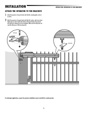
Make sure the trolley does not reach the fully open or fully closed position. Tighten the nut until it reaches the bottom of the gate bracket, then turn the nut a half turn, making sure not ...
Make sure the trolley does not reach the fully open or fully closed position. Tighten the nut until it reaches the bottom of the gate bracket, then turn the nut a half turn, making sure not ...
LA500 Manual
Page 18
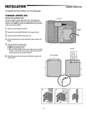
... Box installation, refer to the expansion board. C. Mount the control box as high as possible for a wall or column mount installation. 1 Remove the screws and open the control box. 2 Disconnect the connector labeled "Main Board" on the expansion board. 3 Remove the expansion board by removing the screws. 4 Select the mounting holes...
... Box installation, refer to the expansion board. C. Mount the control box as high as possible for a wall or column mount installation. 1 Remove the screws and open the control box. 2 Disconnect the connector labeled "Main Board" on the expansion board. 3 Remove the expansion board by removing the screws. 4 Select the mounting holes...
LA500 Manual
Page 19
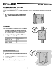
...diameter 'U' bolt. TYPE AND SIZE Standard 3" Round Pipe Standard 4" Square Post Standard 6" Square Post 'U' BOLT OPENING 3-1/2" 4" 6" 90° 2 3 WALL OR COLUMN MOUNT 2 Remove the electrical outlet cover by opening the door 90°. Mount the control box as high as possible for the 33AH battery application. 2 The ...the door from the hinges and set aside until the installation is complete. 1 POST MOUNT NOTE: The post mount option is level. 1 Open the control box. INSTALLATION LARGE METAL CONTROL BOX (XLM) LARGE METAL CONTROL BOX (XLM) MOUNT THE CONTROL BOX (XLM) The control box ...
...diameter 'U' bolt. TYPE AND SIZE Standard 3" Round Pipe Standard 4" Square Post Standard 6" Square Post 'U' BOLT OPENING 3-1/2" 4" 6" 90° 2 3 WALL OR COLUMN MOUNT 2 Remove the electrical outlet cover by opening the door 90°. Mount the control box as high as possible for the 33AH battery application. 2 The ...the door from the hinges and set aside until the installation is complete. 1 POST MOUNT NOTE: The post mount option is level. 1 Open the control box. INSTALLATION LARGE METAL CONTROL BOX (XLM) LARGE METAL CONTROL BOX (XLM) MOUNT THE CONTROL BOX (XLM) The control box ...
LA500 Manual
Page 20
... devices MUST be installed to protect anyone who may come near a moving gate. • Locate entrapment protection devices to protect in BOTH the open and close gate cycles. • Locate entrapment protection devices to protect between moving gate and RIGID objects, such as posts or walls. 1 Connect... 2 Run wire from the earth ground rod to the "Accessory Features on the Control Board" section on the CLOSE EDGE terminal. • Open Entrapment Protection: Connect wires from the entrapment protection device to the Inputs on page 31. SHADOW CLOSE EYES/ INTERRUPT -+ SET PEN SET CL SE...
... devices MUST be installed to protect anyone who may come near a moving gate. • Locate entrapment protection devices to protect in BOTH the open and close gate cycles. • Locate entrapment protection devices to protect between moving gate and RIGID objects, such as posts or walls. 1 Connect... 2 Run wire from the earth ground rod to the "Accessory Features on the Control Board" section on the CLOSE EDGE terminal. • Open Entrapment Protection: Connect wires from the entrapment protection device to the Inputs on page 31. SHADOW CLOSE EYES/ INTERRUPT -+ SET PEN SET CL SE...
LA500 Manual
Page 22
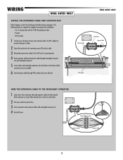
... required to complete the junction box installation: • 4 x 4 Junction Box with 3/4" NPT threaded port holes • Screws • PVC Conduit 1 Trench across driveway to cables. 2 Open the junction box by removing screws (4) and set aside. 3 Mount the junction box within 3 feet (0.9 m) of second operator. 4 Route operator cable and extension cable through...
... required to complete the junction box installation: • 4 x 4 Junction Box with 3/4" NPT threaded port holes • Screws • PVC Conduit 1 Trench across driveway to cables. 2 Open the junction box by removing screws (4) and set aside. 3 Mount the junction box within 3 feet (0.9 m) of second operator. 4 Route operator cable and extension cable through...
LA500 Manual
Page 23
.../ CHARGER + ! ! NOTE: The gate with nut. 3 Insert the extension cable through the knockout and tighten with the longer travel span (opening) must be set to Gate 2 connector on the control board. This gate is no appropriate location on that the control box be set as ... a gate, the gate with a decorative overlapping piece on the same side as shown. 5 Tighten the watertight connector nut to secure extension cable to open first and close second. S T OPEN SET CLOSE OFF O XM T ER OK MOVE GATE E E SE O E IN LMT 0 2 5 60 E STOP TATUS OF 80 I PUT POW R T MER A T ...
.../ CHARGER + ! ! NOTE: The gate with nut. 3 Insert the extension cable through the knockout and tighten with the longer travel span (opening) must be set to Gate 2 connector on the control board. This gate is no appropriate location on that the control box be set as ... a gate, the gate with a decorative overlapping piece on the same side as shown. 5 Tighten the watertight connector nut to secure extension cable to open first and close second. S T OPEN SET CLOSE OFF O XM T ER OK MOVE GATE E E SE O E IN LMT 0 2 5 60 E STOP TATUS OF 80 I PUT POW R T MER A T ...
LA500 Manual
Page 25
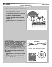
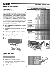
...from one solar panel to the black wire (-) of sunlight during the winter months. The solar panel(s) must be located in an open area clear of two 10W solar panels in series and two 7AH batteries are charged in northern climates where temperatures reach below 32˚.... SEE ACCESSORIES. For solar applications, a minimum of obstructions and shading for areas that reach below -4˚F. WIRING POWER WIRING CONTINUED... We recommend LiftMaster low power draw accessories to minimize power draw, refer to the J15 plug labeled BATT(-)(+) DC(-)(+) on the control board. 5 Plug in series...
...from one solar panel to the black wire (-) of sunlight during the winter months. The solar panel(s) must be located in an open area clear of two 10W solar panels in series and two 7AH batteries are charged in northern climates where temperatures reach below 32˚.... SEE ACCESSORIES. For solar applications, a minimum of obstructions and shading for areas that reach below -4˚F. WIRING POWER WIRING CONTINUED... We recommend LiftMaster low power draw accessories to minimize power draw, refer to the J15 plug labeled BATT(-)(+) DC(-)(+) on the control board. 5 Plug in series...
LA500 Manual
Page 27
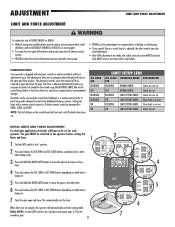
...move gate. • NEVER use force adjustments to compensate for the secondary gate. 25 7 The limits can be set . 7 Cycle the gate open and close. INTRODUCTION Your operator is designed with electronic controls to make travel limits) is adjusted, the other limit. 6 Press and release the SET... CLOSE or SET OPEN button depending on which limit is not set . ADJUSTMENT LIMIT AND FORCE ADJUSTMENT LIMIT AND FORCE ADJUSTMENT To reduce the risk of SEVERE INJURY...
...move gate. • NEVER use force adjustments to compensate for the secondary gate. 25 7 The limits can be set . 7 Cycle the gate open and close. INTRODUCTION Your operator is designed with electronic controls to make travel limits) is adjusted, the other limit. 6 Press and release the SET... CLOSE or SET OPEN button depending on which limit is not set . ADJUSTMENT LIMIT AND FORCE ADJUSTMENT LIMIT AND FORCE ADJUSTMENT To reduce the risk of SEVERE INJURY...


