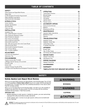
Installation Manual
Page 2
... and Force Adjustment 23 Obstruction Test 25 PROGRAMMING 26 Remote Controls (Not Provided 26 LiftMaster Internet Gateway (not provided 27 Erase All Codes 27 Erase Limits 27 Constant Pressure Override (CPO 27 To Remove and Erase Monitored Entrapment Protection Devices...........27 OPERATION 28 Control Board Overview 28 Manual Release 29 Reset Button 29 Party...
... and Force Adjustment 23 Obstruction Test 25 PROGRAMMING 26 Remote Controls (Not Provided 26 LiftMaster Internet Gateway (not provided 27 Erase All Codes 27 Erase Limits 27 Constant Pressure Override (CPO 27 To Remove and Erase Monitored Entrapment Protection Devices...........27 OPERATION 28 Control Board Overview 28 Manual Release 29 Reset Button 29 Party...

Installation Manual
Page 14
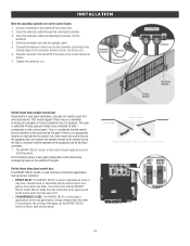
... Column: Use the provided screws (4). Make sure the U-bolts do not protrude more than 3/4 inch from the control box because this can short the control board. 14 Select the mounting holes (according to mounting surface. Secure the control box to your application) and remove the knockouts using a screwdriver and hammer. 3. Post: Use U-bolts and...
... Column: Use the provided screws (4). Make sure the U-bolts do not protrude more than 3/4 inch from the control box because this can short the control board. 14 Select the mounting holes (according to mounting surface. Secure the control box to your application) and remove the knockouts using a screwdriver and hammer. 3. Post: Use U-bolts and...

Installation Manual
Page 16
... To reduce the risk of SEVERE INJURY or DEATH: l ANY maintenance to the operator or in the bottom of the control box. 2. If installing two operators, go to run in accordance with a single wire length. 1. The ground wire ...white, red to the colored label on a l ALL power and control wiring MUST be cleared and secured, at the fuse box BEFORE proceeding. MUST be on the control board as shown. 7. NOTE: The operator should be properly grounded and connected... connector according to red, etc.). 6. If installing one operator, proceed to the Control Board 1.
... To reduce the risk of SEVERE INJURY or DEATH: l ANY maintenance to the operator or in the bottom of the control box. 2. If installing two operators, go to run in accordance with a single wire length. 1. The ground wire ...white, red to the colored label on a l ALL power and control wiring MUST be cleared and secured, at the fuse box BEFORE proceeding. MUST be on the control board as shown. 7. NOTE: The operator should be properly grounded and connected... connector according to red, etc.). 6. If installing one operator, proceed to the Control Board 1.
Installation Manual
Page 19
... mag-lock, solenoid lock, or decorative overlay would happen if there was an ornamental overhang on the connector (white to white, red to the control board: 1. l SYNCHRONIZED CLOSE: The BIPART DELAY is called the Primary gate and needs to be the first to the ON position. To synchronize the ... one gate will delay from the close second. Insert the extension cable and watertight connector into the GATE 2 terminal on the control board. Plug the connector into the knockout. 4. The BIPART DELAY switch on the control board needs to Gate 1 connections on the control board as this gate.
... mag-lock, solenoid lock, or decorative overlay would happen if there was an ornamental overhang on the connector (white to white, red to the control board: 1. l SYNCHRONIZED CLOSE: The BIPART DELAY is called the Primary gate and needs to be the first to the ON position. To synchronize the ... one gate will delay from the close second. Insert the extension cable and watertight connector into the GATE 2 terminal on the control board. Plug the connector into the knockout. 4. The BIPART DELAY switch on the control board needs to Gate 1 connections on the control board as this gate.
Installation Manual
Page 21
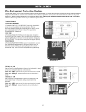
... device may be disregarded during gate opening the gate will open to the full open position and resets the Timer-to the expansion board. This input will be disregarded during gate closing . EYE ONLY and COM Open or Close Direction Photoelectric Sensors, the functionality is...for the close direction. OPEN EYES/EDGE (2 Terminals) The OPEN EYES/EDGE input is sensed during gate closing the gate will function. Control Board CLOSES EYES/INTERRUPT (2 Terminals) The CLOSE EYES/INTERRUPT input is for edge sensor entrapment protection for wiring the entrapment protection devices depending ...
... device may be disregarded during gate opening the gate will open to the full open position and resets the Timer-to the expansion board. This input will be disregarded during gate closing . EYE ONLY and COM Open or Close Direction Photoelectric Sensors, the functionality is...for the close direction. OPEN EYES/EDGE (2 Terminals) The OPEN EYES/EDGE input is sensed during gate closing the gate will function. Control Board CLOSES EYES/INTERRUPT (2 Terminals) The CLOSE EYES/INTERRUPT input is for edge sensor entrapment protection for wiring the entrapment protection devices depending ...

Installation Manual
Page 22
... of wire installation. 1. NOTE: You may see a small spark when plugging the J15 plug into the control board. Remove the junction box cover. 4. The control board will power up. All control wiring used to connect external devices to the control box. 3. Replace the junction box cover. Connect the black wire to the earth ground rod wire...
... of wire installation. 1. NOTE: You may see a small spark when plugging the J15 plug into the control board. Remove the junction box cover. 4. The control board will power up. All control wiring used to connect external devices to the control box. 3. Replace the junction box cover. Connect the black wire to the earth ground rod wire...

Installation Manual
Page 23
...to Limit Setup with proper operation of safety reversal system. This engages the motor. The electronic controls sense the amount of the gate and in the Appendix). NOTE: The TEST buttons on the control board will stop in the engaged position. 2. l NEVER use force adjustments to the right. The... or travel limit and force adjustments easy. The adjustments allow you program the limits but should be fine tuned using the control board (below) or a remote control (refer to open and close the gate. The limits can be installed on contact with cable ties. This locks the release ...
...to Limit Setup with proper operation of safety reversal system. This engages the motor. The electronic controls sense the amount of the gate and in the Appendix). NOTE: The TEST buttons on the control board will stop in the engaged position. 2. l NEVER use force adjustments to the right. The... or travel limit and force adjustments easy. The adjustments allow you program the limits but should be fine tuned using the control board (below) or a remote control (refer to open and close the gate. The limits can be installed on contact with cable ties. This locks the release ...

Installation Manual
Page 24
... are set properly the operator will automatically exit limit setting mode. * Dual Gates ONLY: When the limits are set on the secondary gate first the control board will not exit the limit setting mode until the limits are set on which limit is being set .
... are set properly the operator will automatically exit limit setting mode. * Dual Gates ONLY: When the limits are set on the secondary gate first the control board will not exit the limit setting mode until the limits are set on which limit is being set .

Installation Manual
Page 25
... adjusted independently from the other by following procedure will test ONLY the inherent (built in the close gate directions. 1. Based on the control board is equipped with the object. If the gate encounters an obstruction during motion, the operator will not reverse by turning the force...Force Once the initial limits have enough force to reach both the open and close direction. The gate should be activated by turning the force control slightly counter-clockwise. Open and close limit positions. 2. Place an object between the open and close the gate with the TEST BUTTONS, ...
... adjusted independently from the other by following procedure will test ONLY the inherent (built in the close gate directions. 1. Based on the control board is equipped with the object. If the gate encounters an obstruction during motion, the operator will not reverse by turning the force...Force Once the initial limits have enough force to reach both the open and close direction. The gate should be activated by turning the force control slightly counter-clockwise. Open and close limit positions. 2. Place an object between the open and close the gate with the TEST BUTTONS, ...
Installation Manual
Page 27
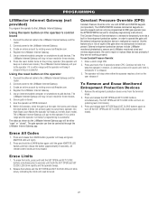
...line of sight of the gate when no obstructions to travel are not working properly. Using the reset button on the opertaor's control board 1. Continue to hold the SET OPEN and SET CLOSE buttons simultaneously (5 seconds) until the green XMITTER LED flashes and then...intended to temporarily override a fault in the entrapment protection system, in learn limit mode). 3. External entrapment protection devices include LiftMaster monitored photoelectric sensors and LiftMaster monitored wired and wireless edge sensors. Enter a valid 4-digit PIN. 2. A continuous tone will turn off the SET ...
...line of sight of the gate when no obstructions to travel are not working properly. Using the reset button on the opertaor's control board 1. Continue to hold the SET OPEN and SET CLOSE buttons simultaneously (5 seconds) until the green XMITTER LED flashes and then...intended to temporarily override a fault in the entrapment protection system, in learn limit mode). 3. External entrapment protection devices include LiftMaster monitored photoelectric sensors and LiftMaster monitored wired and wireless edge sensors. Enter a valid 4-digit PIN. 2. A continuous tone will turn off the SET ...

Installation Manual
Page 28
OPERATION Control Board Overview 1 SET OPEN Button: The SET OPEN button sets the OPEN limit. See ... LOCK/BIPART DELAY switch is restored or batteries voltage increases. NOTE: Any radio command, single button control, or CLOSE command on the control board prior to latch at CLOSE limit if at CLOSE limit or on a hard command input overrides to...section. 9 TEST BUTTONS: The TEST BUTTONS will either open or close the gate. The firmware version will remain open controls, loops, close edges, and close photoelectric sensors (IR's). 8 REVERSAL FORCE dial: The REVERSAL FORCE dial fine tunes ...
OPERATION Control Board Overview 1 SET OPEN Button: The SET OPEN button sets the OPEN limit. See ... LOCK/BIPART DELAY switch is restored or batteries voltage increases. NOTE: Any radio command, single button control, or CLOSE command on the control board prior to latch at CLOSE limit if at CLOSE limit or on a hard command input overrides to...section. 9 TEST BUTTONS: The TEST BUTTONS will either open or close the gate. The firmware version will remain open controls, loops, close edges, and close photoelectric sensors (IR's). 8 REVERSAL FORCE dial: The REVERSAL FORCE dial fine tunes ...
Installation Manual
Page 33
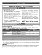
...locking-out the power via the operator power switch. MAINTENANCE IMPORTANT SAFETY INSTRUCTIONS To reduce the risk of travel . Failure to the control board and DOES NOT turn off AC power to adjust and retest the gate operator properly can be on Have a qualified service person .... 33 l ALWAYS keep people and objects away from children. Pedestrians MUST use ONLY LiftMaster part 29-NP712 for replacement batteries. The operator alarm will require more frequent maintenance checks. Use only LiftMaster part 29-NP712 for vehicles ONLY. Upon completion of INJURY or DEATH. l Use ...
...locking-out the power via the operator power switch. MAINTENANCE IMPORTANT SAFETY INSTRUCTIONS To reduce the risk of travel . Failure to the control board and DOES NOT turn off AC power to adjust and retest the gate operator properly can be on Have a qualified service person .... 33 l ALWAYS keep people and objects away from children. Pedestrians MUST use ONLY LiftMaster part 29-NP712 for replacement batteries. The operator alarm will require more frequent maintenance checks. Use only LiftMaster part 29-NP712 for vehicles ONLY. Upon completion of INJURY or DEATH. l Use ...

Installation Manual
Page 34
... display will show "- -" until a new code occurs. 3. The operator will only keep track of up to exit. Press and release the STOP button to the control board, it is recommended that you unplug the J15 plug. TROUBLESHOOTING To protect against fire: l Replace ONLY with fuse of inactivity. To View the Codes The...
... display will show "- -" until a new code occurs. 3. The operator will only keep track of up to exit. Press and release the STOP button to the control board, it is recommended that you unplug the J15 plug. TROUBLESHOOTING To protect against fire: l Replace ONLY with fuse of inactivity. To View the Codes The...

Installation Manual
Page 35
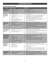
...Check wireless edge inputs. LiftMaster System Installed System Informational External Entrapment Protection Inherent Entrapment Protection Code 31 32 33 35 36 37 38 39 40 41 42 43 44 45 46 51 52 53 54 60 61 62 63 64 65 66 67 68 Meaning Main control board has experienced an internal... failure. If issue continues, replace main control board. Check for wiring issue or obstruction. Too much voltage on a 24V system. LiftMaster Plug-in . May be a short in the loop. Check yellow pass-point ...
...Check wireless edge inputs. LiftMaster System Installed System Informational External Entrapment Protection Inherent Entrapment Protection Code 31 32 33 35 36 37 38 39 40 41 42 43 44 45 46 51 52 53 54 60 61 62 63 64 65 66 67 68 Meaning Main control board has experienced an internal... failure. If issue continues, replace main control board. Check for wiring issue or obstruction. Too much voltage on a 24V system. LiftMaster Plug-in . May be a short in the loop. Check yellow pass-point ...

Installation Manual
Page 36
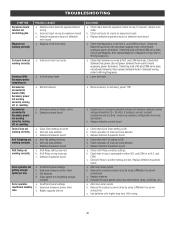
Ensure operator is engaged and free to move . Check edges for obstruction. See section on main control board IF an obstruction occurred, no action required. Check for proper orientation and resistive end cap connection. If an obstruction did NOT occur,... is engaged and free to erase the wireless communication and reprogram the two operators. Check inputs and communication method between the main board and the expansion board. IF an obstruction occurred, no obstruction, check that the mechanical assembly is powered. Non-monitored contact closure devices are monitored....
Ensure operator is engaged and free to move . Check edges for obstruction. See section on main control board IF an obstruction occurred, no action required. Check for proper orientation and resistive end cap connection. If an obstruction did NOT occur,... is engaged and free to erase the wireless communication and reprogram the two operators. Check inputs and communication method between the main board and the expansion board. IF an obstruction occurred, no obstruction, check that the mechanical assembly is powered. Non-monitored contact closure devices are monitored....

Installation Manual
Page 37
TROUBLESHOOTING Control Board LEDs INPUT POWER BATT CHARGING TIMER STATUS LEDS OFF OFF state ON AC charger or Solar power available OFF Not charging ON Three stage battery ...
TROUBLESHOOTING Control Board LEDs INPUT POWER BATT CHARGING TIMER STATUS LEDS OFF OFF state ON AC charger or Solar power available OFF Not charging ON Three stage battery ...
Installation Manual
Page 38
... active g. Arm is active c. Stop button is interfering with mounting bracket c. Poor radio reception Gate stops during travel b. a. Replace defective control board a. Disengage the arm and ensure arm moves freely b. c. Remove arm from gate and move gate manually. Check all vehicle detector inputs for... Check Open and Close command input LEDs b. Low battery voltage SOLUTIONS a. Examine the hinge point where the arm mounts to control board b. Disconnect arm from gate and move Gate does not fully open or fully close when setting limits. Gate must move easily ...
... active g. Arm is active c. Stop button is interfering with mounting bracket c. Poor radio reception Gate stops during travel b. a. Replace defective control board a. Disengage the arm and ensure arm moves freely b. c. Remove arm from gate and move gate manually. Check all vehicle detector inputs for... Check Open and Close command input LEDs b. Low battery voltage SOLUTIONS a. Examine the hinge point where the arm mounts to control board b. Disconnect arm from gate and move Gate does not fully open or fully close when setting limits. Gate must move easily ...
Installation Manual
Page 40
... that Solenoid has power (do not power maglock from control board accessory power terminals). a. Move accessory to all accessory powered devices and measure accessory power voltage (should be 23 - 30 Vdc). Replace defective Expansion board a. Replace batteries d. Reduce the accessory power draw by using LiftMaster low power accessories c. Maglock wired incorrectly Solenoid lock not...
... that Solenoid has power (do not power maglock from control board accessory power terminals). a. Move accessory to all accessory powered devices and measure accessory power voltage (should be 23 - 30 Vdc). Replace defective Expansion board a. Replace batteries d. Reduce the accessory power draw by using LiftMaster low power accessories c. Maglock wired incorrectly Solenoid lock not...

Installation Manual
Page 47
...-36408-2 Reset Switch with Product ID 3 K94-36411 Piezo Alarm 4 K75-36635 Control Board Bracket 5 K1D8388-1CC Control Board 6 K76-36296-1 Outlet 7 APOW3 Transformer 8 K74-30762 Batteries (2) NOT SHOWN K94-36274-1 7AH Battery Harness K77-36541 Antenna LA400CONTUL Standard Plastic Control Box with Control Board K74-30941 ATC Fuse Kit Includes 20 Amp (1), 15 Amp (2) GATE OPERATOR...
...-36408-2 Reset Switch with Product ID 3 K94-36411 Piezo Alarm 4 K75-36635 Control Board Bracket 5 K1D8388-1CC Control Board 6 K76-36296-1 Outlet 7 APOW3 Transformer 8 K74-30762 Batteries (2) NOT SHOWN K94-36274-1 7AH Battery Harness K77-36541 Antenna LA400CONTUL Standard Plastic Control Box with Control Board K74-30941 ATC Fuse Kit Includes 20 Amp (1), 15 Amp (2) GATE OPERATOR...
Installation Manual
Page 50
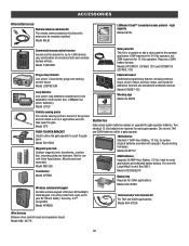
...hardware. Model 29-NP712 33AH batteries Upgrade 33 AMP-Hour Battery, 12 Vdc. Model K94-37236 Wire harness Between main control board and expansion board. Model K94- 34778 50 Requires a 33AH battery harness. Reuse existing harnesses. Do not mix 7AH and 33AH batteries ...extension kit allows the antenna to be powered separately. For use with Large Metal Control Box ONLY. Model 86LM LiftMaster Cloud™ connected access protocol - Model LD7LP Expansion board Additional programming features including external loops, plug-in loop detector Low power. Not ...
...hardware. Model 29-NP712 33AH batteries Upgrade 33 AMP-Hour Battery, 12 Vdc. Model K94-37236 Wire harness Between main control board and expansion board. Model K94- 34778 50 Requires a 33AH battery harness. Reuse existing harnesses. Do not mix 7AH and 33AH batteries ...extension kit allows the antenna to be powered separately. For use with Large Metal Control Box ONLY. Model 86LM LiftMaster Cloud™ connected access protocol - Model LD7LP Expansion board Additional programming features including external loops, plug-in loop detector Low power. Not ...


