
LA400UL Product Data Sheet
Page 1
... REMOTE CONTROL ACCESS Security+ 2.0® 3-channel receiver will handle up to 16 ft. operator can be programmed with anti-tailgate or quick close PROGRAMMABLE AUXILIARY RELAYS With optional expansion board - LA400PKGUL SWING GATE OPERATOR SECTION 32 31 00 KEY FEATURES BATTERY BACKUP Up to 97 days of AC power or battery depletion LIMIT SETTING Electronic DUAL-GATE CONTROL Bi-part delay or synchronized close capabilities HOMELINK® COMPATIBLE Version 4 and higher SPECIFICATIONS OPERATOR SPEED 90-degree opening...
... REMOTE CONTROL ACCESS Security+ 2.0® 3-channel receiver will handle up to 16 ft. operator can be programmed with anti-tailgate or quick close PROGRAMMABLE AUXILIARY RELAYS With optional expansion board - LA400PKGUL SWING GATE OPERATOR SECTION 32 31 00 KEY FEATURES BATTERY BACKUP Up to 97 days of AC power or battery depletion LIMIT SETTING Electronic DUAL-GATE CONTROL Bi-part delay or synchronized close capabilities HOMELINK® COMPATIBLE Version 4 and higher SPECIFICATIONS OPERATOR SPEED 90-degree opening...
Installation Manual
Page 2
... MAINTENANCE 33 Important Safety Instructions 33 Maintenance Chart 33 Batteries 33 TROUBLESHOOTING 34 Diagnostic Codes 34 Diagnostic Codes Table 35 Control Board LEDs 37 Troubleshooting Chart 38 APPENDIX 41 Bracket Types 41 Step 10 Solar Panels 42 Limit Setup with a Remote Control 46 REPAIR PARTS 47 Standard Control Box 47 Gate Operator Arm 47 WIRING DIAGRAM 48 Standard Control Box 48 ACCESSORIES 49 WARRANTY 51 TEMPLATE FOR POST BRACKET MOUNTING 52 SAFETY Safety Symbol and Signal Word Review When you see this manual and follow all safety instructions...
... MAINTENANCE 33 Important Safety Instructions 33 Maintenance Chart 33 Batteries 33 TROUBLESHOOTING 34 Diagnostic Codes 34 Diagnostic Codes Table 35 Control Board LEDs 37 Troubleshooting Chart 38 APPENDIX 41 Bracket Types 41 Step 10 Solar Panels 42 Limit Setup with a Remote Control 46 REPAIR PARTS 47 Standard Control Box 47 Gate Operator Arm 47 WIRING DIAGRAM 48 Standard Control Box 48 ACCESSORIES 49 WARRANTY 51 TEMPLATE FOR POST BRACKET MOUNTING 52 SAFETY Safety Symbol and Signal Word Review When you see this manual and follow all safety instructions...

Installation Manual
Page 3
... or more single family units), hotel, garages, retail store, or other restricted access locations not servicing the general public, in either the open or close direction. Residential Vehicular Gate Operator A vehicular gate operator (or system) intended for use in the other locations not accessible by security personnel. Restricted Access Vehicular Gate Operator A vehicular gate operator (or system) intended for use in garages or parking areas associated with gate controls. l SAVE THESE INSTRUCTIONS. 3 Industrial/Limited Access Vehicular Gate A vehicular gate operator (or...
... or more single family units), hotel, garages, retail store, or other restricted access locations not servicing the general public, in either the open or close direction. Residential Vehicular Gate Operator A vehicular gate operator (or system) intended for use in the other locations not accessible by security personnel. Restricted Access Vehicular Gate Operator A vehicular gate operator (or system) intended for use in garages or parking areas associated with gate controls. l SAVE THESE INSTRUCTIONS. 3 Industrial/Limited Access Vehicular Gate A vehicular gate operator (or...

Installation Manual
Page 4
.... A wireless device shall function under , around or through the gate to prevent unauthorized use conditions. Gate systems 9. application. 10. Install the gate operator only when: 12. Each gate system is prevented from any location in the area 2. Reference owner's manual regarding placement of force in both directions prior to promote pedestrian usage. Vehicular gate systems provide convenience and security. application. SAFETY Safety Installation Information 1. A hard wired contact sensor shall be located...
.... A wireless device shall function under , around or through the gate to prevent unauthorized use conditions. Gate systems 9. application. 10. Install the gate operator only when: 12. Each gate system is prevented from any location in the area 2. Reference owner's manual regarding placement of force in both directions prior to promote pedestrian usage. Vehicular gate systems provide convenience and security. application. SAFETY Safety Installation Information 1. A hard wired contact sensor shall be located...

Installation Manual
Page 16
... on the control board as shown. 7. Step 7 Wire the Operator Arm to page 18. l ALL power wiring should be visible and clearly l Disconnect power at that time the unit may be made by a qualified individual. Connect the operator cable wires to the connector according to the colored label on a dedicated circuit and well protected. switch. If installing two operators, go to red, etc.). 6. Step 6 Earth Ground Rod Use the...
... on the control board as shown. 7. Step 7 Wire the Operator Arm to page 18. l ALL power wiring should be visible and clearly l Disconnect power at that time the unit may be made by a qualified individual. Connect the operator cable wires to the connector according to the colored label on a dedicated circuit and well protected. switch. If installing two operators, go to red, etc.). 6. Step 6 Earth Ground Rod Use the...

Installation Manual
Page 17
... time than wireless applications. Both operators will beep and the yellow NETWORK LEDs will require the installation of programming mode after 180 seconds. 3. Press and hold the LEARN button for the other operator. 17 Repeat the steps for 5 seconds. Do not use wired and wireless communication simultaneously. Wired dual gate applications will light. 6. Wireless dual gates will turn off indicating programming is successful. The yellow NETWORK LED will blink (operator will time out of two control boxes...
... time than wireless applications. Both operators will beep and the yellow NETWORK LEDs will require the installation of programming mode after 180 seconds. 3. Press and hold the LEARN button for the other operator. 17 Repeat the steps for 5 seconds. Do not use wired and wireless communication simultaneously. Wired dual gate applications will light. 6. Wireless dual gates will turn off indicating programming is successful. The yellow NETWORK LED will blink (operator will time out of two control boxes...
Installation Manual
Page 21
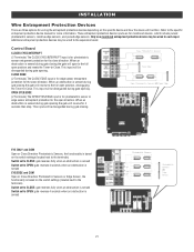
... then stop. Control Board CLOSES EYES/INTERRUPT (2 Terminals) The CLOSE EYES/INTERRUPT input is sensed during gate closing the gate will reverse to the full open position and resets the Timer-to -Close. When an obstruction is sensed during gate opening the gate will function. When an obstruction is sensed during gate closing the gate will open to the full open position, disengaging the Timer-to -Close. INSTALLATION Wire Entrapment Protection Devices There are for more information. Additional...
... then stop. Control Board CLOSES EYES/INTERRUPT (2 Terminals) The CLOSE EYES/INTERRUPT input is sensed during gate closing the gate will reverse to the full open position and resets the Timer-to -Close. When an obstruction is sensed during gate opening the gate will function. When an obstruction is sensed during gate closing the gate will open to the full open position, disengaging the Timer-to -Close. INSTALLATION Wire Entrapment Protection Devices There are for more information. Additional...

Installation Manual
Page 26
... LED will light). Press and release the LEARN button (operator will beep and green XMITTER LED will time out of programming mode after 30 seconds. 2. NOTICE: This device complies with the limits for a Class B digital device, pursuant to the operator, the first keyless entry will not be programmed. This equipment generates, uses and can be programmed to close the gate. 1. PROGRAMMING Remote Controls (Not Provided) A total of 50 Security+ 2.0® remote controls or KPW250 keypads and 2 keyless entries (1 PIN for each remote control button...
... LED will light). Press and release the LEARN button (operator will beep and green XMITTER LED will time out of programming mode after 30 seconds. 2. NOTICE: This device complies with the limits for a Class B digital device, pursuant to the operator, the first keyless entry will not be programmed. This equipment generates, uses and can be programmed to close the gate. 1. PROGRAMMING Remote Controls (Not Provided) A total of 50 Security+ 2.0® remote controls or KPW250 keypads and 2 keyless entries (1 PIN for each remote control button...
Installation Manual
Page 27
... gate is intended to temporarily override a fault in the entrapment protection system, in learn mode for use Constant Pressure Override: 1. The KPW5/KPW250 wireless commercial keypads are not working properly. The Constant Pressure Override feature is at the open " or "closed . 7. Press and release the LEARN button (operator will beep and green XMITTER LED will stop when either "open limit press and release the reset button 3 times (on (entering learn limit mode). Release the buttons and the SET OPEN and SET CLOSE LEDs will blink...
... gate is intended to temporarily override a fault in the entrapment protection system, in learn mode for use Constant Pressure Override: 1. The KPW5/KPW250 wireless commercial keypads are not working properly. The Constant Pressure Override feature is at the open " or "closed . 7. Press and release the LEARN button (operator will beep and green XMITTER LED will stop when either "open limit press and release the reset button 3 times (on (entering learn limit mode). Release the buttons and the SET OPEN and SET CLOSE LEDs will blink...

Installation Manual
Page 28
... Force Adjustment section. 9 TEST BUTTONS: The TEST BUTTONS will close the gate. See Status LED Chart in Limit setting mode. l Option select switch set to CLOSE forces gate to automatically close photoelectric sensors (IR's). 8 REVERSAL FORCE dial: The REVERSAL FORCE dial fine tunes the force. The TTC is restored or battery voltage increases. See Bipart Delay section. 6 LEARN Button: The LEARN button is factory set to latch at CLOSE limit if at a limit until the operator receives another command from the open controls, loops, close edges, and close...
... Force Adjustment section. 9 TEST BUTTONS: The TEST BUTTONS will close the gate. See Status LED Chart in Limit setting mode. l Option select switch set to CLOSE forces gate to automatically close photoelectric sensors (IR's). 8 REVERSAL FORCE dial: The REVERSAL FORCE dial fine tunes the force. The TTC is restored or battery voltage increases. See Bipart Delay section. 6 LEARN Button: The LEARN button is factory set to latch at CLOSE limit if at a limit until the operator receives another command from the open controls, loops, close edges, and close...

Installation Manual
Page 29
... 4-digit PIN when the gate is at the Open Limit and the timer is canceled. Turn the key counter-clockwise 180°. 3. The operator is normal and has no effect on the side of the following to -Close. Reset Button The reset button is in manual mode and the gate can be opened and closed manually. l Press the reset button to -Close. Party Mode Press the reset button once while the gate is located on function. Operator is...
... 4-digit PIN when the gate is at the Open Limit and the timer is canceled. Turn the key counter-clockwise 180°. 3. The operator is normal and has no effect on the side of the following to -Close. Reset Button The reset button is in manual mode and the gate can be opened and closed manually. l Press the reset button to -Close. Party Mode Press the reset button once while the gate is located on function. Operator is...
Installation Manual
Page 33
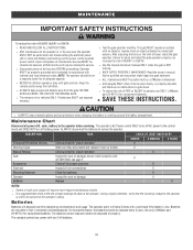
... wire connections Check for tightness Inspect for vehicles ONLY. DESCRIPTION TASK CHECK AT LEAST ONCE EVERY Entrapment Protection Devices Warning Signs Manual Release Gate Accessories Electrical Mounting Hardware Operator Batteries Check and test for proper operation Make sure they are no obstructions to persons use separate entrance. The standard control box comes with gate controls. MAINTENANCE IMPORTANT SAFETY INSTRUCTIONS To reduce the risk of adequate capacity. After adjusting the force...
... wire connections Check for tightness Inspect for vehicles ONLY. DESCRIPTION TASK CHECK AT LEAST ONCE EVERY Entrapment Protection Devices Warning Signs Manual Release Gate Accessories Electrical Mounting Hardware Operator Batteries Check and test for proper operation Make sure they are no obstructions to persons use separate entrance. The standard control box comes with gate controls. MAINTENANCE IMPORTANT SAFETY INSTRUCTIONS To reduce the risk of adequate capacity. After adjusting the force...

Installation Manual
Page 35
... detected (Arm 2) Brownout occurred Wireless Second Operator Communication Error Minimum number of monitoring Solution Disconnect all power, wait 15 seconds, then reconnect power (reboot). Make sure there is not saved it will operate only after installation of a minimum of the battery charge harness. LiftMaster Plug-in wireless edge. Replace batteries in Loop Detector only) Check loop wiring throughout connection. If limits are not. Review monitored entrapment protection device connections. This swing gate operator will briefly...
... detected (Arm 2) Brownout occurred Wireless Second Operator Communication Error Minimum number of monitoring Solution Disconnect all power, wait 15 seconds, then reconnect power (reboot). Make sure there is not saved it will operate only after installation of a minimum of the battery charge harness. LiftMaster Plug-in wireless edge. Replace batteries in Loop Detector only) Check loop wiring throughout connection. If limits are not. Review monitored entrapment protection device connections. This swing gate operator will briefly...

Installation Manual
Page 36
... (expansion board) Open input (EYE/EDGE) communication fault (expansion board) Non-monitored device detected on the wireless safety system Force Reversal (Operator 1) Force Reversal (Operator 2) RPM / STALL Reversal (Operator 1) RPM / STALL Reversal (Operator 2) Normal Operation Solution IF an obstruction occurred, no obstruction, check that the mechanical assembly is engaged and free to move . Make sure connected devices are not supported. If an obstruction did NOT occur, check alignment, inputs, and wiring on Limit and Force Adjustment, and...
... (expansion board) Open input (EYE/EDGE) communication fault (expansion board) Non-monitored device detected on the wireless safety system Force Reversal (Operator 1) Force Reversal (Operator 2) RPM / STALL Reversal (Operator 1) RPM / STALL Reversal (Operator 2) Normal Operation Solution IF an obstruction occurred, no obstruction, check that the mechanical assembly is engaged and free to move . Make sure connected devices are not supported. If an obstruction did NOT occur, check alignment, inputs, and wiring on Limit and Force Adjustment, and...
Installation Manual
Page 38
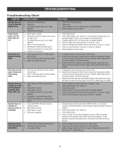
...-learn wireless control/transmitter to the gate post. b. Check if similar wired control operates correctly. Arm moves, but motor does not run and diagnostic display not on " detector g. If on battery power only, low or dead batteries e. Arm does not extend or retract enough during travel and reverses immediately. Poor radio reception Gate stops during travel b. Check Stop button is not "stuck on the stop circuit c. Replace defective control board a. Gate must move Gate does not fully open or fully close when setting limits. Check operator's antenna...
...-learn wireless control/transmitter to the gate post. b. Check if similar wired control operates correctly. Arm moves, but motor does not run and diagnostic display not on " detector g. If on battery power only, low or dead batteries e. Arm does not extend or retract enough during travel and reverses immediately. Poor radio reception Gate stops during travel b. Check Stop button is not "stuck on the stop circuit c. Replace defective control board a. Gate must move Gate does not fully open or fully close when setting limits. Check operator's antenna...
Installation Manual
Page 39
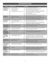
... may reverse direction. Obstruction in gate's path does not cause gate to open limit. Alarm beeps when running on batteries and battery voltage must be 23.0 Vdc or higher. Double entrapment occurred (two obstructions within a single activation) a. Charge batteries by AC or solar power or replace batteries a. Check all Open inputs for cause of both operator's Bipart switch settings. Adjust settings as needed a. Review Shadow loop detector settings. b. Check Timer-to-Close (TTC) setting g. a. b. Replace defective edge sensor...
... may reverse direction. Obstruction in gate's path does not cause gate to open limit. Alarm beeps when running on batteries and battery voltage must be 23.0 Vdc or higher. Double entrapment occurred (two obstructions within a single activation) a. Charge batteries by AC or solar power or replace batteries a. Check all Open inputs for cause of both operator's Bipart switch settings. Adjust settings as needed a. Review Shadow loop detector settings. b. Check Timer-to-Close (TTC) setting g. a. b. Replace defective edge sensor...
Installation Manual
Page 50
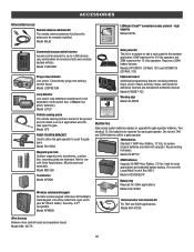
...; compatible. Model K94-37236 Wire harness Between main control board and expansion board. Model CP3 PUSH-TO-OPEN BRACKET Used to allow the gate operator to 1,000 devices (any combination of remote controls and wireless keyless entries). Model LOOPDETLM Loop Detector Low power loop detectors mounted and wired separately inside control box. Model K10-36183 Universal solar wire harness kit For 7AH and 33AH applications. Model 29-NP712 33AH batteries Upgrade 33 AMP-Hour Battery, 12 Vdc. high capacity Model CAPXL Commercial access control receiver Access control receiver for 33AH...
...; compatible. Model K94-37236 Wire harness Between main control board and expansion board. Model CP3 PUSH-TO-OPEN BRACKET Used to allow the gate operator to 1,000 devices (any combination of remote controls and wireless keyless entries). Model LOOPDETLM Loop Detector Low power loop detectors mounted and wired separately inside control box. Model K10-36183 Universal solar wire harness kit For 7AH and 33AH applications. Model 29-NP712 33AH batteries Upgrade 33 AMP-Hour Battery, 12 Vdc. high capacity Model CAPXL Commercial access control receiver Access control receiver for 33AH...
Installation Manual
Page 51
... option. THIS LIMITED WARRANTY DOES NOT COVER NON-DEFECT DAMAGE, DAMAGE CAUSED BY IMPROPER INSTALLATION, OPERATION OR CARE (INCLUDING, BUT NOT LIMITED TO ABUSE, MISUSE, FAILURE TO PROVIDE REASONABLE AND NECESSARY MAINTENANCE, UNAUTHORIZED REPAIRS OR ANY ALTERATIONS TO THIS PRODUCT), LABOR CHARGES FOR REINSTALLING A REPAIRED OR REPLACED UNIT, OR REPLACEMENT OF BATTERIES. Failure to comply strictly with new or factoryrebuilt parts at no cost...
... option. THIS LIMITED WARRANTY DOES NOT COVER NON-DEFECT DAMAGE, DAMAGE CAUSED BY IMPROPER INSTALLATION, OPERATION OR CARE (INCLUDING, BUT NOT LIMITED TO ABUSE, MISUSE, FAILURE TO PROVIDE REASONABLE AND NECESSARY MAINTENANCE, UNAUTHORIZED REPAIRS OR ANY ALTERATIONS TO THIS PRODUCT), LABOR CHARGES FOR REINSTALLING A REPAIRED OR REPLACED UNIT, OR REPLACEMENT OF BATTERIES. Failure to comply strictly with new or factoryrebuilt parts at no cost...
LA400UL Wiring Diagram
Page 1
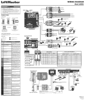
... installed with a single screw ALARM Red Black RESET BUTTON PLUG-IN TRANSFORMER Black Red LiftMaster.com © 2018, LiftMaster All Rights Reserved 01-39240-10 No battery at boot up to "20"). Review power supply and wiring. Make sure connected devices are not accurate, reprogram. If no obstruction, check the operator wiring and that the mechanical assembly is engaged and free to AUX RELAY 2. Replace APE assembly. 99 Normal Operation No action required COAXIAL CABLE ANTENNA Control DIAGNOSTICS Board DIAGNOSTICS DIAGNOSTICS DIAGNOSTICS DIAGNOSTICS DIAGNOSTICS...
... installed with a single screw ALARM Red Black RESET BUTTON PLUG-IN TRANSFORMER Black Red LiftMaster.com © 2018, LiftMaster All Rights Reserved 01-39240-10 No battery at boot up to "20"). Review power supply and wiring. Make sure connected devices are not accurate, reprogram. If no obstruction, check the operator wiring and that the mechanical assembly is engaged and free to AUX RELAY 2. Replace APE assembly. 99 Normal Operation No action required COAXIAL CABLE ANTENNA Control DIAGNOSTICS Board DIAGNOSTICS DIAGNOSTICS DIAGNOSTICS DIAGNOSTICS DIAGNOSTICS...
LA400PKGUL Product Guide - English
Page 1
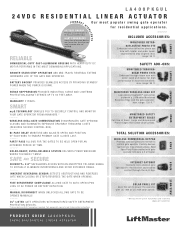
... solar panels. **Wireless kit for residential applications. max. INHERENT REVERSING SENSOR DETECTS OBSTRUCTIONS AND REVERSES GATE WHEN CLOSING OR STOPS/REVERSES THE GATE WHEN OPENING. TOTAL SOLUTION ACCESSORIES: WIRELESS COMMERCIAL KEYPAD Provides constant pressure override to control gate operator if safety devices fault yet are free of Small, Large and Wraparound Profile Edges that sense obstructions. MANUAL DISCONNECT WHEN UNLOCKED ALLOWS GATE TO BE OPEN ED M A NUA L LY. Test equipment regularly and follow safety instructions. BATTERY BACKUP...
... solar panels. **Wireless kit for residential applications. max. INHERENT REVERSING SENSOR DETECTS OBSTRUCTIONS AND REVERSES GATE WHEN CLOSING OR STOPS/REVERSES THE GATE WHEN OPENING. TOTAL SOLUTION ACCESSORIES: WIRELESS COMMERCIAL KEYPAD Provides constant pressure override to control gate operator if safety devices fault yet are free of Small, Large and Wraparound Profile Edges that sense obstructions. MANUAL DISCONNECT WHEN UNLOCKED ALLOWS GATE TO BE OPEN ED M A NUA L LY. Test equipment regularly and follow safety instructions. BATTERY BACKUP...


