

LA400UL Product Data Sheet
Page 1
...AC power or battery depletion LIMIT SETTING Electronic DUAL-GATE CONTROL Bi-part delay or synchronized close capabilities HOMELINK® COMPATIBLE Version 4 and higher SPECIFICATIONS OPERATOR SPEED 90-degree opening in length or weighing up to 850 lbs. operator...Reference detailed solar chart on product page at LiftMaster.com DIAGNOSTIC DISPLAY LED diagnostic display WIRELESS DUAL-GATE COMMUNICATION Eliminates expensive conduit costs and unsightly driveway scars FIRE DEPARTMENT COMPLIANT Allows gate to auto open upon loss of standby power or 400 ...
...AC power or battery depletion LIMIT SETTING Electronic DUAL-GATE CONTROL Bi-part delay or synchronized close capabilities HOMELINK® COMPATIBLE Version 4 and higher SPECIFICATIONS OPERATOR SPEED 90-degree opening in length or weighing up to 850 lbs. operator...Reference detailed solar chart on product page at LiftMaster.com DIAGNOSTIC DISPLAY LED diagnostic display WIRELESS DUAL-GATE COMMUNICATION Eliminates expensive conduit costs and unsightly driveway scars FIRE DEPARTMENT COMPLIANT Allows gate to auto open upon loss of standby power or 400 ...

Installation Manual
Page 3
... buildings accessible by security personnel. UL325 Entrapment Protection Requirements l A minimum of INJURY or DEATH. Industrial/Limited Access Vehicular Gate A vehicular gate operator (or system) intended for both entrapment protection devices. Read the owner's manual. Have a qualified service person make...retail store, or other restricted access locations not servicing the general public, in either the open or close direction. Commercial/General Access Vehicular Gate A vehicular gate operator (or system) intended for vehicles ONLY. Class IV - It is not moving. The...
... buildings accessible by security personnel. UL325 Entrapment Protection Requirements l A minimum of INJURY or DEATH. Industrial/Limited Access Vehicular Gate A vehicular gate operator (or system) intended for both entrapment protection devices. Read the owner's manual. Have a qualified service person make...retail store, or other restricted access locations not servicing the general public, in either the open or close direction. Commercial/General Access Vehicular Gate A vehicular gate operator (or system) intended for vehicles ONLY. Class IV - It is not moving. The...

Installation Manual
Page 4
..., such as the bystander. component part of the reset control shall not cause component. Install the gate operator only when: 12. Swinging gates shall not open into every design. Outdoor or easily accessible controls shall have a security feature to potential hazards. 11. ...wiring arranged so the communication between the gate and adjacent structures when opening . Activation of a gate system. A minimum of travel , one that enough clearance is supplied between the sensor and the gate operator is installed. The gate must be installed in its function as...
..., such as the bystander. component part of the reset control shall not cause component. Install the gate operator only when: 12. Swinging gates shall not open into every design. Outdoor or easily accessible controls shall have a security feature to potential hazards. 11. ...wiring arranged so the communication between the gate and adjacent structures when opening . Activation of a gate system. A minimum of travel , one that enough clearance is supplied between the sensor and the gate operator is installed. The gate must be installed in its function as...

Installation Manual
Page 5
...other fixed object when the gate moves toward the fully open position, subject to the provisions of this specification. 2.4 When the gate of an automated gate system requires replacement, the new gate shall conform to the provisions in 3.1.1.1 and 3.1.1.2 1.3 Gates shall have smooth bottom edges,... in Section 3.1.1.1, the distance operated gate is disconnected, in accordance with the gate when in the open position shall not exceed 4 inches (102 mm), measured from the supporting hardware. General Requirements 3. a swing gate when in the open position shall not be less than...
...other fixed object when the gate moves toward the fully open position, subject to the provisions of this specification. 2.4 When the gate of an automated gate system requires replacement, the new gate shall conform to the provisions in 3.1.1.1 and 3.1.1.2 1.3 Gates shall have smooth bottom edges,... in Section 3.1.1.1, the distance operated gate is disconnected, in accordance with the gate when in the open position shall not exceed 4 inches (102 mm), measured from the supporting hardware. General Requirements 3. a swing gate when in the open position shall not be less than...

Installation Manual
Page 6
... 5/16"-18 x 1-1/2" (1) Keylock Cap Hex Bolt 3/8"-16 x 1-1/2" (1) Hex Nut 3/8"-16 (3) Carriage Bolt 3/8" x 5-15/16" (2) Optional Accessories Push-to-Open Bracket (Model 50-19503) If your application requires the gate to be pushed open, a push-to-open bracket is required, see Accessories. 6 Key (2) Pin (2) Flat Washer 3/8" (3) Hairpin Clip (2) Lock Washer 3/8" (3) Expansion Board (Model K1D8387-1CC...
... 5/16"-18 x 1-1/2" (1) Keylock Cap Hex Bolt 3/8"-16 x 1-1/2" (1) Hex Nut 3/8"-16 (3) Carriage Bolt 3/8" x 5-15/16" (2) Optional Accessories Push-to-Open Bracket (Model 50-19503) If your application requires the gate to be pushed open, a push-to-open bracket is required, see Accessories. 6 Key (2) Pin (2) Flat Washer 3/8" (3) Hairpin Clip (2) Lock Washer 3/8" (3) Expansion Board (Model K1D8387-1CC...

Installation Manual
Page 7
... Main board - up to 3 entrapment protection devices configurable to either close entrapment protection devices and 1 open direction and up to 2 close or open entrapment protection device. INTRODUCTION Operator Specifications Usage Classification Main AC Supply System Operating Voltage Accessory Power Solar Power... Max Maximum Gate Weight/Length 90 Degree Travel Time* Maximum Travel Range* Maximum Daily...
... Main board - up to 3 entrapment protection devices configurable to either close entrapment protection devices and 1 open direction and up to 2 close or open entrapment protection device. INTRODUCTION Operator Specifications Usage Classification Main AC Supply System Operating Voltage Accessory Power Solar Power... Max Maximum Gate Weight/Length 90 Degree Travel Time* Maximum Travel Range* Maximum Daily...

Installation Manual
Page 8
...the property, where easily visible. Suggested for low and high voltage. Gate Gate must fit specifications of operator (refer to complete a site survey and determine the best device for your gate Gate MUST be level. Gate MUST have a smooth bottom edge, no protrusions should exist. Before ... the gate to page 4). Install a warning sign (two provided) on the inside and outside of gate. INTRODUCTION Site Preparation Check the national and local building codes BEFORE installation. Conduit must be constructed and installed according to ASTM F2200 standards (refer to stay open when ...
...the property, where easily visible. Suggested for low and high voltage. Gate Gate must fit specifications of operator (refer to complete a site survey and determine the best device for your gate Gate MUST be level. Gate MUST have a smooth bottom edge, no protrusions should exist. Before ... the gate to page 4). Install a warning sign (two provided) on the inside and outside of gate. INTRODUCTION Site Preparation Check the national and local building codes BEFORE installation. Conduit must be constructed and installed according to ASTM F2200 standards (refer to stay open when ...

Installation Manual
Page 10
Insert the bolt through both brackets and secure with washer, lock washer and nut. 5. Assemble gate post bracket by placing pull-to operator using pins and hairpin clips. 10 Attach post bracket assembly to -open bracket on the release lever and turn it 180° counterclockwise. 2. The operator is now in manual mode. 3. Insert the key into the lock on top of post bracket. 4. Turn the release lever 180° counterclockwise. Attach gate bracket to Operator 1. INSTALLATION Step 1 Attach Brackets to operator using pins and hairpin clips. 6.
Insert the bolt through both brackets and secure with washer, lock washer and nut. 5. Assemble gate post bracket by placing pull-to operator using pins and hairpin clips. 10 Attach post bracket assembly to -open bracket on the release lever and turn it 180° counterclockwise. 2. The operator is now in manual mode. 3. Insert the key into the lock on top of post bracket. 4. Turn the release lever 180° counterclockwise. Attach gate bracket to Operator 1. INSTALLATION Step 1 Attach Brackets to operator using pins and hairpin clips. 6.

Installation Manual
Page 12
... hex bolt through pull-to-open bracket to desired open bracket. 3. Place the operator arm against gate. 2. Manually open and close the gate. 2. Test Gate Travel NOTE: If gate does not open and close completely adjust the position of the gate bracket and mark new mounting holes. 1. Temporarily secure the gate bracket using a clamp. 4. The gate operator (arm) must be mounted...
... hex bolt through pull-to-open bracket to desired open bracket. 3. Place the operator arm against gate. 2. Manually open and close the gate. 2. Test Gate Travel NOTE: If gate does not open and close completely adjust the position of the gate bracket and mark new mounting holes. 1. Temporarily secure the gate bracket using a clamp. 4. The gate operator (arm) must be mounted...

Installation Manual
Page 13
... the clamp and the operator, set aside. 2. Secure the post bracket to the gate using hardware. Drill holes in the gate post. 3. Drill adequate holes in gate (or reinforcement, if necessary) that it opens and closes fully. 13 Manually move the gate to verify that are large enough for the post bracket. Some installations may...
... the clamp and the operator, set aside. 2. Secure the post bracket to the gate using hardware. Drill holes in the gate post. 3. Drill adequate holes in gate (or reinforcement, if necessary) that it opens and closes fully. 13 Manually move the gate to verify that are large enough for the post bracket. Some installations may...

Installation Manual
Page 14
INSTALLATION Step 5 Install the Control Box Standard Control Box The control box MUST be mounted within 5 feet (1.52 m) of the gate operator. Select the mounting holes (according to ensure a watertight seal. Wall or Column: Use the provided screws (4). Make sure the U-bolts do not ... box because this can short the control board. 14 Mount the control box as high as possible for best radio reception. Remove the screws and open the control box. 2. Post: Use U-bolts and rubber washers (not provided) to your application) and remove the knockouts using a screwdriver and hammer. 3. Make ...
INSTALLATION Step 5 Install the Control Box Standard Control Box The control box MUST be mounted within 5 feet (1.52 m) of the gate operator. Select the mounting holes (according to ensure a watertight seal. Wall or Column: Use the provided screws (4). Make sure the U-bolts do not ... box because this can short the control board. 14 Mount the control box as high as possible for best radio reception. Remove the screws and open the control box. 2. Post: Use U-bolts and rubber washers (not provided) to your application) and remove the knockouts using a screwdriver and hammer. 3. Make ...

Installation Manual
Page 15
...and bottom) and knock out using the provided screws (4). TYPE AND SIZE Standard 3" Round Pipe Standard 4" Square Post Standard 6" Square Post 'U' BOLT OPENING 3-1/2" 4" 6" 15 INSTALLATION Large Metal Control Box (XLSOLARCONTUL) The control box MUST be mounted to a post with U-bolts and rubber washers (not ...1. Use knock outs located at the 4 corners of the gate operator. Post Mount NOTE: The post mount option is level. Lift the door from the hinges and set aside until the installation is complete. 2. Open the control box. Secure the control box to mounting surface with...
...and bottom) and knock out using the provided screws (4). TYPE AND SIZE Standard 3" Round Pipe Standard 4" Square Post Standard 6" Square Post 'U' BOLT OPENING 3-1/2" 4" 6" 15 INSTALLATION Large Metal Control Box (XLSOLARCONTUL) The control box MUST be mounted to a post with U-bolts and rubber washers (not ...1. Use knock outs located at the 4 corners of the gate operator. Post Mount NOTE: The post mount option is level. Lift the door from the hinges and set aside until the installation is complete. 2. Open the control box. Secure the control box to mounting surface with...

Installation Manual
Page 17
... steps 1-7. NOTE: We recommend that all accessories and board configurations are two options for each operator arm. Press and release the OPEN test button to your application. Press and release the LEARN button on the same operator. Both operators will beep and the yellow...indicating programming is successful. The yellow NETWORK LED will blink (operator will have a longer battery standby time than wireless applications. Wired dual gate applications will beep) then turn off indicating successful deactivation. 4. Press and release the LEARN button again on the primary operator. Press ...
... steps 1-7. NOTE: We recommend that all accessories and board configurations are two options for each operator arm. Press and release the OPEN test button to your application. Press and release the LEARN button on the same operator. Both operators will beep and the yellow...indicating programming is successful. The yellow NETWORK LED will blink (operator will have a longer battery standby time than wireless applications. Wired dual gate applications will beep) then turn off indicating successful deactivation. 4. Press and release the LEARN button again on the primary operator. Press ...
Installation Manual
Page 21
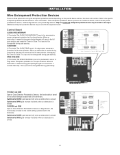
... entrapment protection for the close direction. When an obstruction is sensed during gate closing. When an obstruction is sensed during gate closing the gate will be disregarded during gate opening. INSTALLATION Wire Entrapment Protection Devices There are for monitored devices, which include..., resistive edge sensors, and pulsed edge sensors. Additional entrapment protection devices may be disregarded during gate opening the gate will open to the full open position and resets the Timer-to the specific entrapment protection device manual for the close direction. This...
... entrapment protection for the close direction. When an obstruction is sensed during gate closing. When an obstruction is sensed during gate closing the gate will be disregarded during gate opening. INSTALLATION Wire Entrapment Protection Devices There are for monitored devices, which include..., resistive edge sensors, and pulsed edge sensors. Additional entrapment protection devices may be disregarded during gate opening the gate will open to the full open position and resets the Timer-to the specific entrapment protection device manual for the close direction. This...

Installation Manual
Page 24
... before setting the limits and force. The gate MUST be set . Press and hold the MOVE GATE buttons to move the gate to enter limit setting mode. 3. Cycle the gate open or close using the TEST BUTTONS. When limits are set the Gate switch to the 2 position and repeat steps... 2-7. Press and hold the MOVE GATE button to move the gate to the open and close limit....
... before setting the limits and force. The gate MUST be set . Press and hold the MOVE GATE buttons to move the gate to enter limit setting mode. 3. Cycle the gate open or close using the TEST BUTTONS. When limits are set the Gate switch to the 2 position and repeat steps... 2-7. Press and hold the MOVE GATE button to move the gate to the open and close limit....

Installation Manual
Page 28
...operator type as LA400DC. The TTC is in the Troubleshooting section. l Option select switch set to 180 seconds, 0 seconds is critically low the gate will either open controls, loops, close edges, and close photoelectric sensors (IR's). 8 REVERSAL FORCE dial: The REVERSAL FORCE dial fine tunes the force. l Critically... and the network. 7 TIMER-TO-CLOSE dial: The TIMER-TO-CLOSE (TTC) dial can be set to the TTC expiring will operate the gate (OPEN, STOP and CLOSE). 10 STATUS LEDs: The STATUS LEDs indicate the status of the operator. See Force Adjustment section. 9 TEST BUTTONS: The ...
...operator type as LA400DC. The TTC is in the Troubleshooting section. l Option select switch set to 180 seconds, 0 seconds is critically low the gate will either open controls, loops, close edges, and close photoelectric sensors (IR's). 8 REVERSAL FORCE dial: The REVERSAL FORCE dial fine tunes the force. l Critically... and the network. 7 TIMER-TO-CLOSE dial: The TIMER-TO-CLOSE (TTC) dial can be set to the TTC expiring will operate the gate (OPEN, STOP and CLOSE). 10 STATUS LEDs: The STATUS LEDs indicate the status of the operator. See Force Adjustment section. 9 TEST BUTTONS: The ...
Installation Manual
Page 39
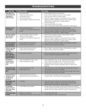
...as needed a. Constant pressure to "ON" b. Alarm beeps three times with LOW BATT option set to open limit. On dual-gate system, incorrect gate opens first or closes first. Defective photoelectric sensor a. Check Fire Dept input f. c. Retest that activating edge sensor causes ... to the Adjustment section to stop and reverse direction. TROUBLESHOOTING SYMPTOM Gate opens, but will not close is available. Gate closes, but will not open or close with a command. Constant pressure to open. Check all Entrapment Protection Device inputs for cause of both operator's...
...as needed a. Constant pressure to "ON" b. Alarm beeps three times with LOW BATT option set to open limit. On dual-gate system, incorrect gate opens first or closes first. Defective photoelectric sensor a. Check Fire Dept input f. c. Retest that activating edge sensor causes ... to the Adjustment section to stop and reverse direction. TROUBLESHOOTING SYMPTOM Gate opens, but will not close is available. Gate closes, but will not open or close with a command. Constant pressure to open. Check all Entrapment Protection Device inputs for cause of both operator's...

Installation Manual
Page 46
...have to set the close position. This automatically sets the force. Perform the "Obstruction Test" after resetting each operator. Once the gate is set the open limit is in the desired close position, press and release the STOP button on the remote control. 3. Initial Limits and Force ... and release the STOP button on the remote control. 3. Press and release the OPEN button on the remote control. 4. Once the gate is in the desired open and close limit is closed. 1. Cycle the gate open position, press and release the STOP button on the remote control again to enter ...
...have to set the close position. This automatically sets the force. Perform the "Obstruction Test" after resetting each operator. Once the gate is set the open limit is in the desired close position, press and release the STOP button on the remote control. 3. Initial Limits and Force ... and release the STOP button on the remote control. 3. Press and release the OPEN button on the remote control. 4. Once the gate is in the desired open and close limit is closed. 1. Cycle the gate open position, press and release the STOP button on the remote control again to enter ...
Installation Manual
Page 50
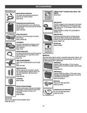
...33AH applications. ACCESSORIES Miscellaneous Remote antenna extension kit The remote antenna extension kit allows the antenna to push the gate open the gate. Model LD7LP Expansion board Additional programming features including external loops, plug-in loop detector Low power. Not for...devices (any combination of remote controls and wireless keyless entries). Model CP3 PUSH-TO-OPEN BRACKET Used to allow the gate operator to be powered separately. Model 86LM LiftMaster Cloud™ connected access protocol - Model LOOPDETLM Loop Detector Low power loop detectors ...
...33AH applications. ACCESSORIES Miscellaneous Remote antenna extension kit The remote antenna extension kit allows the antenna to push the gate open the gate. Model LD7LP Expansion board Additional programming features including external loops, plug-in loop detector Low power. Not for...devices (any combination of remote controls and wireless keyless entries). Model CP3 PUSH-TO-OPEN BRACKET Used to allow the gate operator to be powered separately. Model 86LM LiftMaster Cloud™ connected access protocol - Model LOOPDETLM Loop Detector Low power loop detectors ...
LA400PKGUL Product Guide - English
Page 1
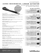
... THE POWER IS DOWN. max. SMART myQ TECHNOLOGY ENABLES YOU TO SECURELY CONTROL AND MONITOR YOUR GATE OPERATOR FROM ANYWHERE.* WIRELESS DUAL-GATE COMMUNICATION SYNCHRONIZES GATE OPENING/ CLOSING AND ELIMINATES EXPENSIVE DRIVEWAY TRENCHING COSTS (REQUIRES SECOND CONTROL BOX). max. max. range: ...TRAVEL REVERSAL EXTEND HARDWARE LIFE OF THE GATE AND OPERATOR. MONITORED WIRELESS EDGE KIT Low-energy Bluetooth® connection between a LiftMaster Monitored Resistive Edge and the gate operator; WARRANTY 2 YEARS. MANUAL DISCONNECT WHEN UNLOCKED ALLOWS GATE TO BE OPEN ED M A NUA L LY. ...
... THE POWER IS DOWN. max. SMART myQ TECHNOLOGY ENABLES YOU TO SECURELY CONTROL AND MONITOR YOUR GATE OPERATOR FROM ANYWHERE.* WIRELESS DUAL-GATE COMMUNICATION SYNCHRONIZES GATE OPENING/ CLOSING AND ELIMINATES EXPENSIVE DRIVEWAY TRENCHING COSTS (REQUIRES SECOND CONTROL BOX). max. max. range: ...TRAVEL REVERSAL EXTEND HARDWARE LIFE OF THE GATE AND OPERATOR. MONITORED WIRELESS EDGE KIT Low-energy Bluetooth® connection between a LiftMaster Monitored Resistive Edge and the gate operator; WARRANTY 2 YEARS. MANUAL DISCONNECT WHEN UNLOCKED ALLOWS GATE TO BE OPEN ED M A NUA L LY. ...


