
LA400 Manual
Page 1
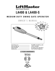
LA400 & LA400-S MEDIUM DUTY SWING GATE OPERATOR OWNER'S MANUAL MeBtOoLaaxplrtC(giXooennLMatrl)ol Serial # Primary Arm Serial # Secondary Arm Serial # Control Box Installation Date The LA400 is intended for use with vehicular swing gates. The operator can be used in Class I, Class II and Class III applications. 2 YEAR WARRANTY Radio Receiver Built on Board 315 MHz
LA400 & LA400-S MEDIUM DUTY SWING GATE OPERATOR OWNER'S MANUAL MeBtOoLaaxplrtC(giXooennLMatrl)ol Serial # Primary Arm Serial # Secondary Arm Serial # Control Box Installation Date The LA400 is intended for use with vehicular swing gates. The operator can be used in Class I, Class II and Class III applications. 2 YEAR WARRANTY Radio Receiver Built on Board 315 MHz

LA400 Manual
Page 2
... Placement Standard Control Box Large Metal Control Box (XLM) WIRING Connect the Gate Operator (Gate 1) to the Control Box Set the Bipart Delay (Model LA400-S Only) Connect the Gate Operator (Gate 2) to the Control Box (Model LA400-S Only) Junction Box (Model LA400-S Only) Connect Transformer to Control Board Earth Ground Rod Installation (Optional) Connect Batteries...
... Placement Standard Control Box Large Metal Control Box (XLM) WIRING Connect the Gate Operator (Gate 1) to the Control Box Set the Bipart Delay (Model LA400-S Only) Connect the Gate Operator (Gate 2) to the Control Box (Model LA400-S Only) Junction Box (Model LA400-S Only) Connect Transformer to Control Board Earth Ground Rod Installation (Optional) Connect Batteries...

LA400 Manual
Page 3
...entrapment protection. Type B2: Connections provided for each gate application. Examples include sirens, horns or buzzers. UL325 ENTRAPMENT PROTECTION REQUIREMENTS GATE OPERATOR ENTRAPMENT PROTECTION UL325 Installation CLASS CLASS I - Non-contact sensors such as gate edges. SAFETY » UL325 MODEL CLASSIFICATIONS CLASS ...for use in both sides of the three UL325 classes. SAFETY ACCESSORY SELECTION All UL325 compliant LiftMaster gate operators will accept external entrapment protection devices to service the general public. Type E: Built-in plain view on this...
...entrapment protection. Type B2: Connections provided for each gate application. Examples include sirens, horns or buzzers. UL325 ENTRAPMENT PROTECTION REQUIREMENTS GATE OPERATOR ENTRAPMENT PROTECTION UL325 Installation CLASS CLASS I - Non-contact sensors such as gate edges. SAFETY » UL325 MODEL CLASSIFICATIONS CLASS ...for use in both sides of the three UL325 classes. SAFETY ACCESSORY SELECTION All UL325 compliant LiftMaster gate operators will accept external entrapment protection devices to service the general public. Type E: Built-in plain view on this...

LA400 Manual
Page 4
...One or more contact sensors shall be designed to prevent unauthorized use conditions. SAFETY » SAFETY INSTALLATION INFORMATION 1. Install the gate operator only when: a. The pedestrian access opening and closing to potential hazards. 3. Outdoor or easily accessible controls shall have a security... feature to promote pedestrian usage. For a gate operator utilizing a non-contact sensor: a. b. Gate systems design and installation must be located at the bottom edge of non-contact sensor...
...One or more contact sensors shall be designed to prevent unauthorized use conditions. SAFETY » SAFETY INSTALLATION INFORMATION 1. Install the gate operator only when: a. The pedestrian access opening and closing to potential hazards. 3. Outdoor or easily accessible controls shall have a security... feature to promote pedestrian usage. For a gate operator utilizing a non-contact sensor: a. b. Gate systems design and installation must be located at the bottom edge of non-contact sensor...

LA400 Manual
Page 5
... 4.1.1.2. 3.1 The following provisions shall apply to Class 1, Class II and Class III vehicular 2.3 Any existing automated gate, when the operator requires replacement, horizontal swing gates: shall be upgraded to conform to ASTM F2200 for the zone specified in accordance with ASTM F2200: ...(102 mm), 3.1.1 All weight bearing exposed rollers 8 feet (2.44 m), or less, above grade 1.7 Protrusions shall not be permitted on an automatically operated gate. 3.2.1 All weight bearing exposed rollers 8 feet (2.44 m), or less, above grade shall be initiated by a swing gate when in the ...
... 4.1.1.2. 3.1 The following provisions shall apply to Class 1, Class II and Class III vehicular 2.3 Any existing automated gate, when the operator requires replacement, horizontal swing gates: shall be upgraded to conform to ASTM F2200 for the zone specified in accordance with ASTM F2200: ...(102 mm), 3.1.1 All weight bearing exposed rollers 8 feet (2.44 m), or less, above grade 1.7 Protrusions shall not be permitted on an automatically operated gate. 3.2.1 All weight bearing exposed rollers 8 feet (2.44 m), or less, above grade shall be initiated by a swing gate when in the ...

LA400 Manual
Page 6
...rigid object. 5 Check with proper weatherproof fixtures. WIRING To reduce the risk of SEVERE INJURY or DEATH: • ANY maintenance to the operator or in the area near a moving gate: • Entrapment protection devices MUST be installed to protect in transformer, it MUST be performed until... moving gate and RIGID objects, such as posts. • A swinging gate shall NOT open and close gate. • NEVER use only LiftMaster part #K74-30762 for disposal instructions. To AVOID damaging plug-in BOTH the open into public access ways. Upon completion of entrapment or obstruction...
...rigid object. 5 Check with proper weatherproof fixtures. WIRING To reduce the risk of SEVERE INJURY or DEATH: • ANY maintenance to the operator or in the area near a moving gate: • Entrapment protection devices MUST be installed to protect in transformer, it MUST be performed until... moving gate and RIGID objects, such as posts. • A swinging gate shall NOT open and close gate. • NEVER use only LiftMaster part #K74-30762 for disposal instructions. To AVOID damaging plug-in BOTH the open into public access ways. Upon completion of entrapment or obstruction...
LA400 Manual
Page 7
...reverse on contact with gate controls. For continued protection against fire and electrocution: • Disconnect power and battery BEFORE installing or servicing operator. After adjusting the force or the limit of same type and rating. 6 To avoid SERIOUS personal INJURY or DEATH from the gate.... Read the ownerʼs manual. Pedestrians MUST use only LiftMaster part #K74-30762 for vehicles ONLY. Have a qualified service person make repairs to persons use separate entrance. • Disconnect ALL power ...
...reverse on contact with gate controls. For continued protection against fire and electrocution: • Disconnect power and battery BEFORE installing or servicing operator. After adjusting the force or the limit of same type and rating. 6 To avoid SERIOUS personal INJURY or DEATH from the gate.... Read the ownerʼs manual. Pedestrians MUST use only LiftMaster part #K74-30762 for vehicles ONLY. Have a qualified service person make repairs to persons use separate entrance. • Disconnect ALL power ...

LA400 Manual
Page 8
..., 9 feet (2.7 m) • Warning Sign (2) • Battery (2) • Plug-in Transformer (1) LA400-S (SECOND GATE OPERATOR ARM) • Motor Cable - Twelve Connectors (1) HARDWARE INVENTORY • Post Bracket (1) • Pull-to...• Anchors (4) • Terminal Block - Six Conductor, 40 feet (12.2 m) • Junction Box - INTRODUCTION » OPERATOR SPECIFICATIONS + CARTON INVENTORY OPERATOR SPECIFICATIONS Operating Cycles: Main Supply (Motor): Current Consumption: Power Consumption: Battery Charger Supply: Maximum Gate Width: Maximum Gate Weight: Protection Class: Travel ...
..., 9 feet (2.7 m) • Warning Sign (2) • Battery (2) • Plug-in Transformer (1) LA400-S (SECOND GATE OPERATOR ARM) • Motor Cable - Twelve Connectors (1) HARDWARE INVENTORY • Post Bracket (1) • Pull-to...• Anchors (4) • Terminal Block - Six Conductor, 40 feet (12.2 m) • Junction Box - INTRODUCTION » OPERATOR SPECIFICATIONS + CARTON INVENTORY OPERATOR SPECIFICATIONS Operating Cycles: Main Supply (Motor): Current Consumption: Power Consumption: Battery Charger Supply: Maximum Gate Width: Maximum Gate Weight: Protection Class: Travel ...
LA400 Manual
Page 9
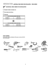
... TRANSFORMER (STRANDED COPPER WIRE) Wire Gauge 14 500 feet (152 m) Wire Gauge 12 1000 feet (305 m) TOOLS NEEDED During assembly, installation and adjustment of the operator, instructions will call for tools as illustrated below. Deep Well Sockets and Wrench 1/2", 5/8", 7/16", 9/16" and 1/4" Carpenter's Level Screwdriver Drill Adjustable End Wrench Drill Bits...
... TRANSFORMER (STRANDED COPPER WIRE) Wire Gauge 14 500 feet (152 m) Wire Gauge 12 1000 feet (305 m) TOOLS NEEDED During assembly, installation and adjustment of the operator, instructions will call for tools as illustrated below. Deep Well Sockets and Wrench 1/2", 5/8", 7/16", 9/16" and 1/4" Carpenter's Level Screwdriver Drill Adjustable End Wrench Drill Bits...

LA400 Manual
Page 10
... string trimmers. Warning Sign Gate Bracket tTpiPKDlehoEaimdyMsEeneiPeosonwttnirCvtlttiriLehIhataeEonnnncsuAgjctghaiRelt!umpiedrrusirGGsaofeyatrratoneteruaowos.vearepmereashnriiyCeaDcntlpaegmeea.rtsonaavhttoeeenClhagetyaanttauernasyonrece Hinge Post Bracket Operator Operator Cable Antenna Control Box with Batteries Hinge Post Bracket Gate Bracket PVC Conduit (not...reduce the risk of entrapment or obstruction exists at either the opening or closing direction. Operator Operator Cable Earth Ground Installation (Optional) 12 Gauge Wire 8 feet (2.4 m) Photoelectric Sensors RIGHT...
... string trimmers. Warning Sign Gate Bracket tTpiPKDlehoEaimdyMsEeneiPeosonwttnirCvtlttiriLehIhataeEonnnncsuAgjctghaiRelt!umpiedrrusirGGsaofeyatrratoneteruaowos.vearepmereashnriiyCeaDcntlpaegmeea.rtsonaavhttoeeenClhagetyaanttauernasyonrece Hinge Post Bracket Operator Operator Cable Antenna Control Box with Batteries Hinge Post Bracket Gate Bracket PVC Conduit (not...reduce the risk of entrapment or obstruction exists at either the opening or closing direction. Operator Operator Cable Earth Ground Installation (Optional) 12 Gauge Wire 8 feet (2.4 m) Photoelectric Sensors RIGHT...
LA400 Manual
Page 11
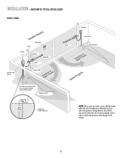
INSTALLATION » OVERVIEW OF TYPICAL INSTALLATION DUAL GATE Warning Sign Hinge Antenna Post Bracket Gate Bracket Gate 1 Control Box with Batteries Operator Cable Gate 2 Junction Box Extension Cable Photoelectric Sensors PVC Conduit (not provided) to reduce the risk of entrapment or obstruction exists at either the opening ...
INSTALLATION » OVERVIEW OF TYPICAL INSTALLATION DUAL GATE Warning Sign Hinge Antenna Post Bracket Gate Bracket Gate 1 Control Box with Batteries Operator Cable Gate 2 Junction Box Extension Cable Photoelectric Sensors PVC Conduit (not provided) to reduce the risk of entrapment or obstruction exists at either the opening ...
LA400 Manual
Page 12
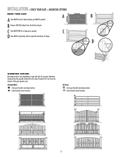
... ground. INSTALLATION » CHECK YOUR GATE + MOUNTING OPTIONS CHECK YOUR GATE A B A Gate MUST be plumb. B Remove ANY/ALL wheels from the bottom of the gate operator arm. C D Gate MUST swing freely and be less than 4 inches (10.2 cm) from the bottom of your gate. RECOMMENDED: = Gate post bracket mounting locations = Gate...
... ground. INSTALLATION » CHECK YOUR GATE + MOUNTING OPTIONS CHECK YOUR GATE A B A Gate MUST be plumb. B Remove ANY/ALL wheels from the bottom of the gate operator arm. C D Gate MUST swing freely and be less than 4 inches (10.2 cm) from the bottom of your gate. RECOMMENDED: = Gate post bracket mounting locations = Gate...
LA400 Manual
Page 13
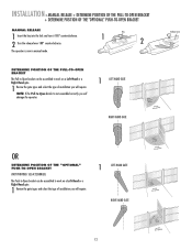
...be assembled to work on a Left-Hand or a Right-Hand gate. 1 Review the gate types and select the type of installation you will damage the operator. 1 LEFT-HAND GATE RIGHT-HAND GATE Release Lever OR DETERMINE POSITION OF THE "OPTIONAL" PUSH-TO-OPEN BRACKET (NOT PROVIDED. Key 1 2 DETERMINE POSITION... OF THE PULL-TO-OPEN BRACKET The Pull-to-Open bracket can be assembled to -Open bracket is now in manual mode. The operator is not assembled correctly you will require. 1 LEFT-HAND GATE RIGHT-HAND GATE 12 NOTE: If the Pull-to work on a Left-Hand or ...
...be assembled to work on a Left-Hand or a Right-Hand gate. 1 Review the gate types and select the type of installation you will damage the operator. 1 LEFT-HAND GATE RIGHT-HAND GATE Release Lever OR DETERMINE POSITION OF THE "OPTIONAL" PUSH-TO-OPEN BRACKET (NOT PROVIDED. Key 1 2 DETERMINE POSITION... OF THE PULL-TO-OPEN BRACKET The Pull-to-Open bracket can be assembled to -Open bracket is now in manual mode. The operator is not assembled correctly you will require. 1 LEFT-HAND GATE RIGHT-HAND GATE 12 NOTE: If the Pull-to work on a Left-Hand or ...
LA400 Manual
Page 14
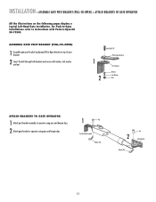
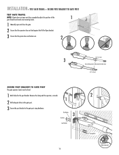
... the illustrations on top of post bracket. 2 Insert the bolt through both brackets and secure with Push-to operator using pins and hairpin clips. 1 Pin Post Bracket Assembly Hairpin Clip Pin 2 Gate Bracket Hairpin Clip 13 ASSEMBLE GATE POST BRACKET (PULL-TO-OPEN) ...with washer, lock washer and nut. 1 2 HeexxBBolot l3t/38/"8" Extension PBurlla-tcok-Oepten Bracket PPoostsBtrBacrkaectket WWaashsehrer LLoockckWaWshaesr her NNuut t ATTACH BRACKETS TO GATE OPERATOR 1 Attach post bracket assembly to operator using pins and hairpin clips. 2 Attach gate bracket to -Open kit 50-19503.
... the illustrations on top of post bracket. 2 Insert the bolt through both brackets and secure with Push-to operator using pins and hairpin clips. 1 Pin Post Bracket Assembly Hairpin Clip Pin 2 Gate Bracket Hairpin Clip 13 ASSEMBLE GATE POST BRACKET (PULL-TO-OPEN) ...with washer, lock washer and nut. 1 2 HeexxBBolot l3t/38/"8" Extension PBurlla-tcok-Oepten Bracket PPoostsBtrBacrkaectket WWaashsehrer LLoockckWaWshaesr her NNuut t ATTACH BRACKETS TO GATE OPERATOR 1 Attach post bracket assembly to operator using pins and hairpin clips. 2 Attach gate bracket to -Open kit 50-19503.
LA400 Manual
Page 15
... • Tape measure. Gate Post Gate Hinge Point Gate Post Gate Hinge Point Gate Post Gate Hinge Point Operator Hinge Point 7" (18 cm) 7" (18 cm) Operator 7" (18 cm) Hinge Point 7" (18 cm) Operator 7" (18 cm) Hinge Point 7" (18 cm) Gate Post Gate Hinge Point Gate Post Gate Hinge Point... Gate Post Gate Hinge Point 7" (18 cm) Operator Hinge Point 7" (18 cm) Operator 7" (18 cm) Hinge Point 7" (18 cm) Operator 7" (18 cm) Hinge Point 7" (18 cm) MEASURING AND MARKING FOR THE GATE BRACKET Before proceeding, begin with the...
... • Tape measure. Gate Post Gate Hinge Point Gate Post Gate Hinge Point Gate Post Gate Hinge Point Operator Hinge Point 7" (18 cm) 7" (18 cm) Operator 7" (18 cm) Hinge Point 7" (18 cm) Operator 7" (18 cm) Hinge Point 7" (18 cm) Gate Post Gate Hinge Point Gate Post Gate Hinge Point... Gate Post Gate Hinge Point 7" (18 cm) Operator Hinge Point 7" (18 cm) Operator 7" (18 cm) Hinge Point 7" (18 cm) Operator 7" (18 cm) Hinge Point 7" (18 cm) MEASURING AND MARKING FOR THE GATE BRACKET Before proceeding, begin with the...
LA400 Manual
Page 16
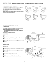
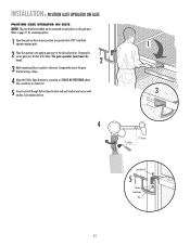
...POSSIBLE above the screwdriver or dowel rod. 5 Insert hex bolt through Pull-to desired open position (no greater than 100°) and hold operator against gate. 2 Place the operator arm against gate post at the desired position. Temporarily secure gate post bracket with washer, lock washer and nut. 1 3 4 7" (18... cm) 7" (18 cm) Hex Bolt 3/8" 5 Washer Lock Washer Nut 15 INSTALLATION » POSITION GATE OPERATOR ON GATE POSITION GATE OPERATOR ON GATE NOTE: The post bracket assembly can be level. 2 3 Mark mounting holes on the gate post.
...POSSIBLE above the screwdriver or dowel rod. 5 Insert hex bolt through Pull-to desired open position (no greater than 100°) and hold operator against gate. 2 Place the operator arm against gate post at the desired position. Temporarily secure gate post bracket with washer, lock washer and nut. 1 3 4 7" (18... cm) 7" (18 cm) Hex Bolt 3/8" 5 Washer Lock Washer Nut 15 INSTALLATION » POSITION GATE OPERATOR ON GATE POSITION GATE OPERATOR ON GATE NOTE: The post bracket assembly can be level. 2 3 Mark mounting holes on the gate post.
LA400 Manual
Page 17
...holes in the gate post. 3 Secure the post bracket to fully extend or fully retract. 1/2" (1.3 cm) SECURE POST BRACKET TO GATE POST The gate operator (arm) must be level. 1 Mark holes for the post bracket. INSTALLATION » TEST GATE TRAVEL + SECURE POST BRACKET TO GATE POST TEST GATE TRAVEL...open and close completely adjust the position of the 1 gate bracket and mark new mounting holes. 1 Manually open and close the gate. 2 Ensure that the operator does not bind against the Pull-to-Open bracket. 3 Ensure that the piston does not bottom out. 2 1/2" (1.3 cm) 3 Do not allow piston ...
...holes in the gate post. 3 Secure the post bracket to fully extend or fully retract. 1/2" (1.3 cm) SECURE POST BRACKET TO GATE POST The gate operator (arm) must be level. 1 Mark holes for the post bracket. INSTALLATION » TEST GATE TRAVEL + SECURE POST BRACKET TO GATE POST TEST GATE TRAVEL...open and close completely adjust the position of the 1 gate bracket and mark new mounting holes. 1 Manually open and close the gate. 2 Ensure that the operator does not bind against the Pull-to-Open bracket. 3 Ensure that the piston does not bottom out. 2 1/2" (1.3 cm) 3 Do not allow piston ...
LA400 Manual
Page 18
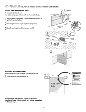
... that it opens and closes fully. Gate may require additional reinforcement be level. Fence Gate Post 1 Gate Gate Travel Path If installing a 2nd operator, repeat the previous installation steps for vehicles only Pedestrians must be installed on both sides of the gate and in the gate area. This entrance... may move the gate to verify that are large enough for the gate bracket mounting hardware. 2 Secure the gate operator to the gate with cable ties. Do not let children operate the gate or play in plain view. 1 Fasten warning signs to the gate using hardware (not provided). 3 ...
... that it opens and closes fully. Gate may require additional reinforcement be level. Fence Gate Post 1 Gate Gate Travel Path If installing a 2nd operator, repeat the previous installation steps for vehicles only Pedestrians must be installed on both sides of the gate and in the gate area. This entrance... may move the gate to verify that are large enough for the gate bracket mounting hardware. 2 Secure the gate operator to the gate with cable ties. Do not let children operate the gate or play in plain view. 1 Fasten warning signs to the gate using hardware (not provided). 3 ...

LA400 Manual
Page 19
... Outs 7 A. Knock Outs B. Wall C. Post B. INSTALLATION » STANDARD CONTROL BOX MOUNT THE CONTROL BOX The control box MUST be mounted within 5 feet (1.5 m) of the gate operator.
... Outs 7 A. Knock Outs B. Wall C. Post B. INSTALLATION » STANDARD CONTROL BOX MOUNT THE CONTROL BOX The control box MUST be mounted within 5 feet (1.5 m) of the gate operator.
LA400 Manual
Page 21
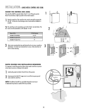
INSTALLATION » LARGE METAL CONTROL BOX (XLM) MOUNT THE CONTROL BOX (XLM) The control box MUST be mounted within 3 feet (0.9 m) of the operator. 2 Connect ground rod with 'U' bolts. See chart below. Ground Screw Standoffs ALARM LOCK SOL GND MAGR GATE 1 BR GR WH YL BL RD ACCESSORY POWER ... to mount up to one of the two green ground screws inside the control box. Use knock outs located at the 4 corners of the gate operator. 1 90° Mount the control box as high as possible for 3 wall or column mounting. ALARM LOCK SOL GND MAGR GATE 1 BR GR WH YL...
INSTALLATION » LARGE METAL CONTROL BOX (XLM) MOUNT THE CONTROL BOX (XLM) The control box MUST be mounted within 3 feet (0.9 m) of the operator. 2 Connect ground rod with 'U' bolts. See chart below. Ground Screw Standoffs ALARM LOCK SOL GND MAGR GATE 1 BR GR WH YL BL RD ACCESSORY POWER ... to mount up to one of the two green ground screws inside the control box. Use knock outs located at the 4 corners of the gate operator. 1 90° Mount the control box as high as possible for 3 wall or column mounting. ALARM LOCK SOL GND MAGR GATE 1 BR GR WH YL...


