

LA400 Manual
Page 2
... Gate Operator (Gate 1) to the Control Box Set the Bipart Delay (Model LA400-S Only) Connect the Gate Operator (Gate 2) to the Control Box (Model LA400-S Only) Junction Box (Model LA400-S Only) Connect Transformer to Control Board Earth Ground Rod Installation (Optional) Connect Batteries 1-6 1 2 3 4 5-6 7-8 7 7 8 8 9-21 9-10 11 11 12 12 12 13 13 14 14...
... Gate Operator (Gate 1) to the Control Box Set the Bipart Delay (Model LA400-S Only) Connect the Gate Operator (Gate 2) to the Control Box (Model LA400-S Only) Junction Box (Model LA400-S Only) Connect Transformer to Control Board Earth Ground Rod Installation (Optional) Connect Batteries 1-6 1 2 3 4 5-6 7-8 7 7 8 8 9-21 9-10 11 11 12 12 12 13 13 14 14...

LA400 Manual
Page 6
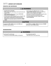
ALWAYS wear protective gloves and eye protection when changing the battery or working around the battery compartment. • DO NOT use only LiftMaster part #K74-30762 for a binding or sticking gate. • If one or more non-contact sensors shall be returned to protect ...• NEVER increase force beyond minimum amount required to close gate. • NEVER use force adjustments to persons use flooded lead acid battery. • Flooded lead acid batteries will interfere with a rigid object. 5 To AVOID damaging gas, power or other control may be located where the risk of FIRE...
ALWAYS wear protective gloves and eye protection when changing the battery or working around the battery compartment. • DO NOT use only LiftMaster part #K74-30762 for a binding or sticking gate. • If one or more non-contact sensors shall be returned to protect ...• NEVER increase force beyond minimum amount required to close gate. • NEVER use force adjustments to persons use flooded lead acid battery. • Flooded lead acid batteries will interfere with a rigid object. 5 To AVOID damaging gas, power or other control may be located where the risk of FIRE...
LA400 Manual
Page 7
...power before performing ANY maintenance. • ALL maintenance MUST be performed by a LiftMaster professional. • SAVE THESE INSTRUCTIONS. For continued protection against fire and electrocution: • Disconnect power and battery BEFORE installing or servicing operator. Failure to gate hardware. • The entrance...on contact with fuse of INJURY or DEATH. • Use the emergency release ONLY when the gate is for replacement batteries. SAFETY » IMPORTANT SAFETY INFORMATION OPERATION AND MAINTENANCE • READ AND FOLLOW ALL INSTRUCTIONS. • NEVER let ...
...power before performing ANY maintenance. • ALL maintenance MUST be performed by a LiftMaster professional. • SAVE THESE INSTRUCTIONS. For continued protection against fire and electrocution: • Disconnect power and battery BEFORE installing or servicing operator. Failure to gate hardware. • The entrance...on contact with fuse of INJURY or DEATH. • Use the emergency release ONLY when the gate is for replacement batteries. SAFETY » IMPORTANT SAFETY INFORMATION OPERATION AND MAINTENANCE • READ AND FOLLOW ALL INSTRUCTIONS. • NEVER let ...

LA400 Manual
Page 8
... Head Mounting Screws (4) • Anchors (4) • Terminal Block - Six Conductor, 9 feet (2.7 m) • Warning Sign (2) • Battery (2) • Plug-in Transformer (1) LA400-S (SECOND GATE OPERATOR ARM) • Motor Cable - Six Conductor, 40 feet (12.2 m) • Junction Box - Twelve Connectors (1) HARDWARE...OPERATOR SPECIFICATIONS + CARTON INVENTORY OPERATOR SPECIFICATIONS Operating Cycles: Main Supply (Motor): Current Consumption: Power Consumption: Battery Charger Supply: Maximum Gate Width: Maximum Gate Weight: Protection Class: Travel Speed: Rated Operating Time: Temperature...
... Head Mounting Screws (4) • Anchors (4) • Terminal Block - Six Conductor, 9 feet (2.7 m) • Warning Sign (2) • Battery (2) • Plug-in Transformer (1) LA400-S (SECOND GATE OPERATOR ARM) • Motor Cable - Six Conductor, 40 feet (12.2 m) • Junction Box - Twelve Connectors (1) HARDWARE...OPERATOR SPECIFICATIONS + CARTON INVENTORY OPERATOR SPECIFICATIONS Operating Cycles: Main Supply (Motor): Current Consumption: Power Consumption: Battery Charger Supply: Maximum Gate Width: Maximum Gate Weight: Protection Class: Travel Speed: Rated Operating Time: Temperature...

LA400 Manual
Page 10
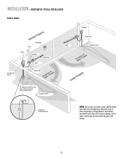
... OVERVIEW OF TYPICAL INSTALLATION LEFT-HAND GATE Warning Sign Antenna Control Box with Batteries Photoelectric Sensors 12 Gauge Wire PVC Conduit (not provided) to protect the low...Warning Sign Gate Bracket tTpiPKDlehoEaimdyMsEeneiPeosonwttnirCvtlttiriLehIhataeEonnnncsuAgjctghaiRelt!umpiedrrusirGGsaofeyatrratoneteruaowos.vearepmereashnriiyCeaDcntlpaegmeea.rtsonaavhttoeeenClhagetyaanttauernasyonrece Hinge Post Bracket Operator Operator Cable Antenna Control Box with Batteries Hinge Post Bracket Gate Bracket PVC Conduit (not provided) to reduce the risk of entrapment or obstruction ...
... OVERVIEW OF TYPICAL INSTALLATION LEFT-HAND GATE Warning Sign Antenna Control Box with Batteries Photoelectric Sensors 12 Gauge Wire PVC Conduit (not provided) to protect the low...Warning Sign Gate Bracket tTpiPKDlehoEaimdyMsEeneiPeosonwttnirCvtlttiriLehIhataeEonnnncsuAgjctghaiRelt!umpiedrrusirGGsaofeyatrratoneteruaowos.vearepmereashnriiyCeaDcntlpaegmeea.rtsonaavhttoeeenClhagetyaanttauernasyonrece Hinge Post Bracket Operator Operator Cable Antenna Control Box with Batteries Hinge Post Bracket Gate Bracket PVC Conduit (not provided) to reduce the risk of entrapment or obstruction ...
LA400 Manual
Page 11
... gate is still moving. 10 INSTALLATION » OVERVIEW OF TYPICAL INSTALLATION DUAL GATE Warning Sign Hinge Antenna Post Bracket Gate Bracket Gate 1 Control Box with Batteries Operator Cable Gate 2 Junction Box Extension Cable Photoelectric Sensors PVC Conduit (not provided) to reduce the risk of entrapment or obstruction exists at either the...
... gate is still moving. 10 INSTALLATION » OVERVIEW OF TYPICAL INSTALLATION DUAL GATE Warning Sign Hinge Antenna Post Bracket Gate Bracket Gate 1 Control Box with Batteries Operator Cable Gate 2 Junction Box Extension Cable Photoelectric Sensors PVC Conduit (not provided) to reduce the risk of entrapment or obstruction exists at either the...

LA400 Manual
Page 19
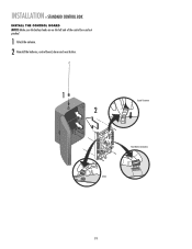
... control box. 1 2 Disconnect the reset button, alarm, and coaxial connector. 3 Loosen screws to remove the control board and mounting bracket. 4 Remove the control board. 5 Remove batteries and set aside. 6 Select mounting holes and knock out using a screwdriver and hammer. 7 Secure the control box to mounting surface using the appropriate hardware (not...
... control box. 1 2 Disconnect the reset button, alarm, and coaxial connector. 3 Loosen screws to remove the control board and mounting bracket. 4 Remove the control board. 5 Remove batteries and set aside. 6 Select mounting holes and knock out using a screwdriver and hammer. 7 Secure the control box to mounting surface using the appropriate hardware (not...
LA400 Manual
Page 20
INSTALLATION » STANDARD CONTROL BOX INSTALL THE CONTROL BOARD NOTE: Make sure the battery leads are on the left side of the control box and not pinched. 1 Attach the antenna. 2 Reinstall the batteries, control board, alarm and reset button. 1 2 Coaxial Connector Reset Button Connections Alarm 19
INSTALLATION » STANDARD CONTROL BOX INSTALL THE CONTROL BOARD NOTE: Make sure the battery leads are on the left side of the control box and not pinched. 1 Attach the antenna. 2 Reinstall the batteries, control board, alarm and reset button. 1 2 Coaxial Connector Reset Button Connections Alarm 19

LA400 Manual
Page 22
... on the application requirements. 2 Depending on the voltage and application the 120 Vac access panel may be used to access the wiring. 3 Connect two 7AH batteries, purchased separately. Follow all instructions for the control board power supply. INSTALLATION » LARGE METAL CONTROL BOX (XLM) WIRING 1 Select the knock out in the...
... on the application requirements. 2 Depending on the voltage and application the 120 Vac access panel may be used to access the wiring. 3 Connect two 7AH batteries, purchased separately. Follow all instructions for the control board power supply. INSTALLATION » LARGE METAL CONTROL BOX (XLM) WIRING 1 Select the knock out in the...
LA400 Manual
Page 29
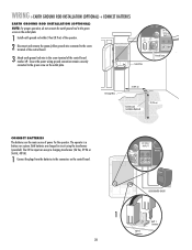
... J4 24 VAC/ SOLAR INPUT Ground Screw 12 Gauge Wire 3' (0.9 m) Earth Ground Installation (Optional) 8' (2.4 m) CONNECT BATTERIES The batteries are charged in circuit using the transformer (provided). Both batteries are the main source of power for the operator. WIRING » EARTH GROUND ROD INSTALLATION (OPTIONAL) + CONNECT...28 The 24 Vac input can accept a charging transformer (26 Vac, 29 VA or 36 Vdc, 40 VA). 1 Connect the plugs from the batteries to the connectors on the outlet plate. 1 Install earth ground rod within 3 feet (0.9 m) of the operator. 2 Disconnect and remove the ...
... J4 24 VAC/ SOLAR INPUT Ground Screw 12 Gauge Wire 3' (0.9 m) Earth Ground Installation (Optional) 8' (2.4 m) CONNECT BATTERIES The batteries are charged in circuit using the transformer (provided). Both batteries are the main source of power for the operator. WIRING » EARTH GROUND ROD INSTALLATION (OPTIONAL) + CONNECT...28 The 24 Vac input can accept a charging transformer (26 Vac, 29 VA or 36 Vdc, 40 VA). 1 Connect the plugs from the batteries to the connectors on the outlet plate. 1 Install earth ground rod within 3 feet (0.9 m) of the operator. 2 Disconnect and remove the ...
LA400 Manual
Page 35
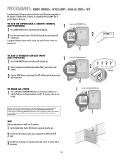
... PROVIDED) 1 Press LEARN XMITTER button and release (LED will activate twice. All previous codes are prohibited, except for changing the code setting or replacing the battery.
... PROVIDED) 1 Press LEARN XMITTER button and release (LED will activate twice. All previous codes are prohibited, except for changing the code setting or replacing the battery.
LA400 Manual
Page 41
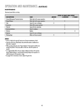
.... • See page 33 for instructions on how to adjust the gate force. DESCRIPTION External Entrapment Protection System Manual Release Gate Accessories Electrical Mounting Hardware Batteries Operator Warning Signs TASK Check and test for proper operation Check and test for proper operation Inspect for wear or damage Check all for proper...
.... • See page 33 for instructions on how to adjust the gate force. DESCRIPTION External Entrapment Protection System Manual Release Gate Accessories Electrical Mounting Hardware Batteries Operator Warning Signs TASK Check and test for proper operation Check and test for proper operation Inspect for wear or damage Check all for proper...

LA400 Manual
Page 42
... Connector 17 DIP Switch 18 Pushbutton 19 Pushbuttons 20 Pushbutton 21 Pushbuttons 22 Pushbutton 23 Potentiometer 24 Potentiometer 25 Potentiometer 26 Connector 41 FUNCTION Alarm Battery 1 Battery 2 S1 Learn Xmitter - Program Remote Gate 1 - Jog Learn Limit Learn Limits Gate 2 - Jog Learn Limit Single Button Force Bipart Delay Timer-to-Close Receiver...
... Connector 17 DIP Switch 18 Pushbutton 19 Pushbuttons 20 Pushbutton 21 Pushbuttons 22 Pushbutton 23 Potentiometer 24 Potentiometer 25 Potentiometer 26 Connector 41 FUNCTION Alarm Battery 1 Battery 2 S1 Learn Xmitter - Program Remote Gate 1 - Jog Learn Limit Learn Limits Gate 2 - Jog Learn Limit Single Button Force Bipart Delay Timer-to-Close Receiver...
LA400 Manual
Page 43
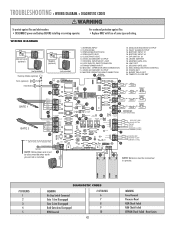
... Reset ROM Check Failed RAM Check Failed EEPROM Check Failed - For continued protection against fire and electrocution: • DISCONNECT power and battery BEFORE installing or servicing operator. WIRING DIAGRAM Solenoid Lock (optional) MAGLOCK NO C NC Maglock (optional) MAGLOCK NO C NC (not...LIMIT SET 21. CLOSE EDGE 3. FAULT ALARM OUTPUT 15. FORCE SET 24. Reset Limits OPERATOR ARM CONNECTION 11. 24VDC ACCESSORY OUTPUT 12. BATTERY INPUT #2 17. BIPART DELAY SET 25. MASTER OPERATOR ARM CONNECTION 1 ANTENNA CONNECTION 13. SBC (SINGLE BUTTON CONTROL) 23. TRANSFORMER INPUT...
... Reset ROM Check Failed RAM Check Failed EEPROM Check Failed - For continued protection against fire and electrocution: • DISCONNECT power and battery BEFORE installing or servicing operator. WIRING DIAGRAM Solenoid Lock (optional) MAGLOCK NO C NC Maglock (optional) MAGLOCK NO C NC (not...LIMIT SET 21. CLOSE EDGE 3. FAULT ALARM OUTPUT 15. FORCE SET 24. Reset Limits OPERATOR ARM CONNECTION 11. 24VDC ACCESSORY OUTPUT 12. BATTERY INPUT #2 17. BIPART DELAY SET 25. MASTER OPERATOR ARM CONNECTION 1 ANTENNA CONNECTION 13. SBC (SINGLE BUTTON CONTROL) 23. TRANSFORMER INPUT...

LA400 Manual
Page 44
...Replace accessory device. 43 Replace control board. Clear all Open/Safety devices from obstruction. Voltage must be >23 V at battery connection. Use reference chart on . Rewire desired accessory device to resume normal operation. See Installation section for adjustment instructions. See... Timer-to-Close not turned on. 2) Gate has opened on . 3) Loose/disconnected wires. 4) Bad accessory device FIX Battery must be >23 V at battery connection. GATE STOPS Gate starts to separate power source. ACCESSORY DEVICE NOT WORKING PROPERLY 1) Not installed properly. 2) Enabling Switch...
...Replace accessory device. 43 Replace control board. Clear all Open/Safety devices from obstruction. Voltage must be >23 V at battery connection. Use reference chart on . Rewire desired accessory device to resume normal operation. See Installation section for adjustment instructions. See... Timer-to-Close not turned on. 2) Gate has opened on . 3) Loose/disconnected wires. 4) Bad accessory device FIX Battery must be >23 V at battery connection. GATE STOPS Gate starts to separate power source. ACCESSORY DEVICE NOT WORKING PROPERLY 1) Not installed properly. 2) Enabling Switch...

LA400 Manual
Page 45
... 8 K76-19446 K74-30941 K001A5747-2 K001A5747 K76-35600 K76-35364 DESCRIPTION QTY Control Board 1 Control Box & Cover with Gasket 1 Control Board Bracket 1 Reset Switch 1 Antenna 1 Battery 2 Transformer 1 Alarm 1 Not Shown ATC Fuse Kit Includes 20 Amp (1), 15 Amp (2) Receiver Module - 390 MHz Receiver Module - 315 MHz Reset Switch (XLM Control Box...
... 8 K76-19446 K74-30941 K001A5747-2 K001A5747 K76-35600 K76-35364 DESCRIPTION QTY Control Board 1 Control Box & Cover with Gasket 1 Control Board Bracket 1 Reset Switch 1 Antenna 1 Battery 2 Transformer 1 Alarm 1 Not Shown ATC Fuse Kit Includes 20 Amp (1), 15 Amp (2) Receiver Module - 390 MHz Receiver Module - 315 MHz Reset Switch (XLM Control Box...
LA400 Manual
Page 46
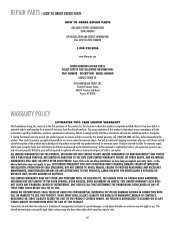
... MAINTENANCE, UNAUTHORIZED REPAIRS OR ANY ALTERATIONS TO THIS PRODUCT), LABOR CHARGES FOR REINSTALLING A REPAIRED OR REPLACED UNIT, OR REPLACEMENT OF BATTERIES. Technical Support Group 6050 S. REPAIR PARTS » HOW TO ORDER REPAIR PARTS HOW TO ORDER REPAIR PARTS OUR LARGE SERVICE ...ORGANIZATION SPANS AMERICA FOR INSTALLATION AND SERVICE INFORMATION, CALL OUR TOLL FREE NUMBER 1-800-528-2806 www.liftmaster.com WHEN ORDERING REPAIR PARTS PLEASE SUPPLY THE FOLLOWING INFORMATION: PART NUMBER DESCRIPTION MODEL NUMBER ADDRESS ORDER TO: THE CHAMBERLAIN GROUP...
... MAINTENANCE, UNAUTHORIZED REPAIRS OR ANY ALTERATIONS TO THIS PRODUCT), LABOR CHARGES FOR REINSTALLING A REPAIRED OR REPLACED UNIT, OR REPLACEMENT OF BATTERIES. Technical Support Group 6050 S. REPAIR PARTS » HOW TO ORDER REPAIR PARTS HOW TO ORDER REPAIR PARTS OUR LARGE SERVICE ...ORGANIZATION SPANS AMERICA FOR INSTALLATION AND SERVICE INFORMATION, CALL OUR TOLL FREE NUMBER 1-800-528-2806 www.liftmaster.com WHEN ORDERING REPAIR PARTS PLEASE SUPPLY THE FOLLOWING INFORMATION: PART NUMBER DESCRIPTION MODEL NUMBER ADDRESS ORDER TO: THE CHAMBERLAIN GROUP...
LA400 Manual
Page 47
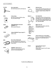
... separate power supply (Model ARMP5). CPS-LN4 7 AH/12 Vdc Gate Access System Battery: The gate access system battery is a replacement battery for increasing the effective range of an emergency. Fail safe operation keeps gate locked if...type housing so it is housed in case of remote controls. Recommended for the operator. To order visit www.liftmaster.com 46 MG1300 Vehicle Exit Sensor: One piece outdoor buried vehicle motion detector with sensing probe is easy to ...to operate gate by entering a password on a specially designed keypad. The model LA400 requires two batteries.
... separate power supply (Model ARMP5). CPS-LN4 7 AH/12 Vdc Gate Access System Battery: The gate access system battery is a replacement battery for increasing the effective range of an emergency. Fail safe operation keeps gate locked if...type housing so it is housed in case of remote controls. Recommended for the operator. To order visit www.liftmaster.com 46 MG1300 Vehicle Exit Sensor: One piece outdoor buried vehicle motion detector with sensing probe is easy to ...to operate gate by entering a password on a specially designed keypad. The model LA400 requires two batteries.
LA400 Push to Open Addendum Manual
Page 2
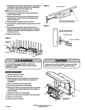
...DEATH from gate post and cross member. 11. Disconnect power to the negative (-) terminals (black). 7. Disconnect terminals leads to both batteries and connect red wires to cross member with 3/8"-16 x 6" carriage bolts, flat washers, lock washers and nuts. Connect black wires..., lock washers and nuts. 13. Secure post bracket assembly to mark holes in use ONLY Chamberlain part #K74-30762 for reinstallation. 4. BATTERY REPLACEMENT 1. Open the control box cover. 3. Install control board and mounting plate. 8. Reattach operator to operator. Remember location of post ...
...DEATH from gate post and cross member. 11. Disconnect power to the negative (-) terminals (black). 7. Disconnect terminals leads to both batteries and connect red wires to cross member with 3/8"-16 x 6" carriage bolts, flat washers, lock washers and nuts. Connect black wires..., lock washers and nuts. 13. Secure post bracket assembly to mark holes in use ONLY Chamberlain part #K74-30762 for reinstallation. 4. BATTERY REPLACEMENT 1. Open the control box cover. 3. Install control board and mounting plate. 8. Reattach operator to operator. Remember location of post ...


