

LA400 Manual
Page 2
... WIRING Connect the Gate Operator (Gate 1) to the Control Box Set the Bipart Delay (Model LA400-S Only) Connect the Gate Operator (Gate 2) to the Control Box (Model LA400-S Only) Junction Box (Model LA400-S Only) Connect Transformer to Control Board Earth Ground Rod Installation (Optional) Connect Batteries 1-6 1...Protection OPERATION AND MAINTENANCE Reset Button Remote Control Manual Release Maintenance TROUBLESHOOTING Basic Control Board Layout Wiring Diagram Diagnostic Codes Troubleshooting Chart REPAIR PARTS Control Box Gate Operator Arm How to Order Repair Parts WARRANTY POLICY ACCESSORIES...
... WIRING Connect the Gate Operator (Gate 1) to the Control Box Set the Bipart Delay (Model LA400-S Only) Connect the Gate Operator (Gate 2) to the Control Box (Model LA400-S Only) Junction Box (Model LA400-S Only) Connect Transformer to Control Board Earth Ground Rod Installation (Optional) Connect Batteries 1-6 1...Protection OPERATION AND MAINTENANCE Reset Button Remote Control Manual Release Maintenance TROUBLESHOOTING Basic Control Board Layout Wiring Diagram Diagnostic Codes Troubleshooting Chart REPAIR PARTS Control Box Gate Operator Arm How to Order Repair Parts WARRANTY POLICY ACCESSORIES...
LA400 Manual
Page 31
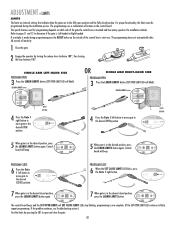
... that indicate when the gates are in the fully open and close the gate. 30 Control SET OPEN LIMIT SET CLOSE LIMIT board will blink). DIAGNOSTIC GATE 1 SET CLOSE 7 When gate is made during the installation process. LIMIT LIMIT 5 When gate is in the desired position, press the...ARM RIGHT-HAND SIDE PROGRAM OPEN 3 Press the LEARN LIMITS button (SET OPEN LIMIT LED will beep. Control SET OPEN SET CLOSE board will blink). DIAGNOSTIC GATE 1 SET CLOSE PROGRAM CLOSE 6 When the SET CLOSE LIMIT LED blinks, press the Gate 1 right button. The programming uses a combination of ...
... that indicate when the gates are in the fully open and close the gate. 30 Control SET OPEN LIMIT SET CLOSE LIMIT board will blink). DIAGNOSTIC GATE 1 SET CLOSE 7 When gate is made during the installation process. LIMIT LIMIT 5 When gate is in the desired position, press the...ARM RIGHT-HAND SIDE PROGRAM OPEN 3 Press the LEARN LIMITS button (SET OPEN LIMIT LED will beep. Control SET OPEN SET CLOSE board will blink). DIAGNOSTIC GATE 1 SET CLOSE PROGRAM CLOSE 6 When the SET CLOSE LIMIT LED blinks, press the Gate 1 right button. The programming uses a combination of ...
LA400 Manual
Page 32
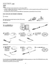
... the gate. 2 Engage the operator by pressing the RESET button. Control board SET SET GATE 2 will blink). DIAGNOSTIC GATE 1 SET CLOSE 9 Press the LEARN LIMITS button. Programming times-out automatically after 60 seconds of inactivity. DIAGNOSTIC GATE 1 SET CLOSE 5 Press the GATE 2 right button to close the left operator. OPEN LIMIT CLOSE...
... the gate. 2 Engage the operator by pressing the RESET button. Control board SET SET GATE 2 will blink). DIAGNOSTIC GATE 1 SET CLOSE 9 Press the LEARN LIMITS button. Programming times-out automatically after 60 seconds of inactivity. DIAGNOSTIC GATE 1 SET CLOSE 5 Press the GATE 2 right button to close the left operator. OPEN LIMIT CLOSE...

LA400 Manual
Page 33
PROGRAM OPEN 3 Press the LEARN LIMITS button (SET OPEN LIMIT LED will beep. Control LIMIT LIMIT FORCE board will blink). DIAGNOSTIC 9 Press the LEARN LIMITS SET GATE 1 button. If the problem continues, see Troubleshooting section.) Test the limits by pressing the SBC to open the right ... and close the right operator. SET CLOSE LIMIT LE LIMIT GATE 2 8 Press the GATE 1 right button to move the left operator into the OPEN position. DIAGNOSTIC GATE 1 SET CLOSE 5 Press the GATE 2 left button to close the gate. 32
PROGRAM OPEN 3 Press the LEARN LIMITS button (SET OPEN LIMIT LED will beep. Control LIMIT LIMIT FORCE board will blink). DIAGNOSTIC 9 Press the LEARN LIMITS SET GATE 1 button. If the problem continues, see Troubleshooting section.) Test the limits by pressing the SBC to open the right ... and close the right operator. SET CLOSE LIMIT LE LIMIT GATE 2 8 Press the GATE 1 right button to move the left operator into the OPEN position. DIAGNOSTIC GATE 1 SET CLOSE 5 Press the GATE 2 left button to close the gate. 32

LA400 Manual
Page 39
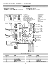
...;E J 1 K5 L1 1 S8 R2 OFF OFF ON SAVE ON MAGLOCK LEARN R1 XMITTER SINGLE NO DUAL MODE NC EDGE 2 F3 NO NC PHOTO S1 K2 DIAGNOSTIC GATE 1 K1 Q9 SET OPEN LIMIT SET CLOSE LIMIT LEARN LIMITS R2Ø7 Z2Ø R227 J18 U4 R224 Z22 R92 R91 R94 R93 CLOSE... edge for optional devices Make sure the rubber seal around the cover is intact and close the cover. Secure the control box cover with the LA400 to control box depending on wire gauge and distance - 300 mA accessory power, 75 mA switched accessory power. These devices have been provided for gates...
...;E J 1 K5 L1 1 S8 R2 OFF OFF ON SAVE ON MAGLOCK LEARN R1 XMITTER SINGLE NO DUAL MODE NC EDGE 2 F3 NO NC PHOTO S1 K2 DIAGNOSTIC GATE 1 K1 Q9 SET OPEN LIMIT SET CLOSE LIMIT LEARN LIMITS R2Ø7 Z2Ø R227 J18 U4 R224 Z22 R92 R91 R94 R93 CLOSE... edge for optional devices Make sure the rubber seal around the cover is intact and close the cover. Secure the control box cover with the LA400 to control box depending on wire gauge and distance - 300 mA accessory power, 75 mA switched accessory power. These devices have been provided for gates...

LA400 Manual
Page 42
...;E J 1 K5 L1 1 S8 R2 OFF OFF ON SAVE ON MAGLOCK LEARN R1 XMITTER SINGLE NO DUAL MODE NC EDGE 2 F3 NO NC PHOTO S1 K2 DIAGNOSTIC GATE 1 K1 Q9 SET OPEN LIMIT SET CLOSE LIMIT LEARN LIMITS R2Ø7 Z2Ø R227 J18 R224 U4 Z22 R92 R91 R94 R93 CLOSE...
...;E J 1 K5 L1 1 S8 R2 OFF OFF ON SAVE ON MAGLOCK LEARN R1 XMITTER SINGLE NO DUAL MODE NC EDGE 2 F3 NO NC PHOTO S1 K2 DIAGNOSTIC GATE 1 K1 Q9 SET OPEN LIMIT SET CLOSE LIMIT LEARN LIMITS R2Ø7 Z2Ø R227 J18 R224 U4 Z22 R92 R91 R94 R93 CLOSE...
LA400 Manual
Page 43
... PHOTO EYE 6. 24VDC ACCESSORY OUTPUT 7. OPERATOR ARM CONNECTION 11. 24VDC ACCESSORY OUTPUT 12. Reset Limits TROUBLESHOOTING » WIRING DIAGRAM + DIAGNOSTIC CODES To protect against fire: • Replace ONLY with fuse of same type and rating. TIMER TO CLOSE SET BLUE YELLOW J ...must 9 be disconnected when earth ground rod is installed. 16 15 NOTE: Batteries must be connected to operate. # OF BLINKS 1 2 3 4 5 DIAGNOSTIC CODES MEANING No Stop Switch Connected Gate 1 Arm Disengaged Gate 2 Arm Disengaged Both Gate Arms Disengaged RPM Reversal # OF BLINKS 6 7 8 9 10 ...
... PHOTO EYE 6. 24VDC ACCESSORY OUTPUT 7. OPERATOR ARM CONNECTION 11. 24VDC ACCESSORY OUTPUT 12. Reset Limits TROUBLESHOOTING » WIRING DIAGRAM + DIAGNOSTIC CODES To protect against fire: • Replace ONLY with fuse of same type and rating. TIMER TO CLOSE SET BLUE YELLOW J ...must 9 be disconnected when earth ground rod is installed. 16 15 NOTE: Batteries must be connected to operate. # OF BLINKS 1 2 3 4 5 DIAGNOSTIC CODES MEANING No Stop Switch Connected Gate 1 Arm Disengaged Gate 2 Arm Disengaged Both Gate Arms Disengaged RPM Reversal # OF BLINKS 6 7 8 9 10 ...

