
LA400 Manual
Page 1
The operator can be used in Class I, Class II and Class III applications. 2 YEAR WARRANTY Radio Receiver Built on Board 315 MHz LA400 & LA400-S MEDIUM DUTY SWING GATE OPERATOR OWNER'S MANUAL MeBtOoLaaxplrtC(giXooennLMatrl)ol Serial # Primary Arm Serial # Secondary Arm Serial # Control Box Installation Date The LA400 is intended for use with vehicular swing gates.
The operator can be used in Class I, Class II and Class III applications. 2 YEAR WARRANTY Radio Receiver Built on Board 315 MHz LA400 & LA400-S MEDIUM DUTY SWING GATE OPERATOR OWNER'S MANUAL MeBtOoLaaxplrtC(giXooennLMatrl)ol Serial # Primary Arm Serial # Secondary Arm Serial # Control Box Installation Date The LA400 is intended for use with vehicular swing gates.

LA400 Manual
Page 2
...Warning Sign Placement Standard Control Box Large Metal Control Box (XLM) WIRING Connect the Gate Operator (Gate 1) to the Control Box Set the Bipart Delay (Model LA400-S Only) Connect the Gate Operator (Gate 2) to the Control Box (Model LA400-S Only) Junction Box (Model LA400-S Only) Connect Transformer to Control Board Earth Ground Rod... Protection OPERATION AND MAINTENANCE Reset Button Remote Control Manual Release Maintenance TROUBLESHOOTING Basic Control Board Layout Wiring Diagram Diagnostic Codes Troubleshooting Chart REPAIR PARTS Control Box Gate Operator Arm How to Order Repair ...
...Warning Sign Placement Standard Control Box Large Metal Control Box (XLM) WIRING Connect the Gate Operator (Gate 1) to the Control Box Set the Bipart Delay (Model LA400-S Only) Connect the Gate Operator (Gate 2) to the Control Box (Model LA400-S Only) Junction Box (Model LA400-S Only) Connect Transformer to Control Board Earth Ground Rod... Protection OPERATION AND MAINTENANCE Reset Button Remote Control Manual Release Maintenance TROUBLESHOOTING Basic Control Board Layout Wiring Diagram Diagnostic Codes Troubleshooting Chart REPAIR PARTS Control Box Gate Operator Arm How to Order Repair ...

LA400 Manual
Page 8
...inventory is doubled except for control box. • Standard Control Box (1) • Hardware Bag (1) • Gate Operator Arm • Motor Cable - Six Conductor, 40 feet (12.2 m) • Junction Box - For Primary (Gate ...1) and Secondary (Gate 2) installation the carton inventory is based on a Single Operator. Six Conductor, 9 feet (2.7 m) • Warning Sign (2) • Battery (2) • Plug-in Transformer (1) LA400...
...inventory is doubled except for control box. • Standard Control Box (1) • Hardware Bag (1) • Gate Operator Arm • Motor Cable - Six Conductor, 40 feet (12.2 m) • Junction Box - For Primary (Gate ...1) and Secondary (Gate 2) installation the carton inventory is based on a Single Operator. Six Conductor, 9 feet (2.7 m) • Warning Sign (2) • Battery (2) • Plug-in Transformer (1) LA400...

LA400 Manual
Page 10
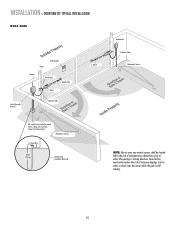
... Gate Bracket tTpiPKDlehoEaimdyMsEeneiPeosonwttnirCvtlttiriLehIhataeEonnnncsuAgjctghaiRelt!umpiedrrusirGGsaofeyatrratoneteruaowos.vearepmereashnriiyCeaDcntlpaegmeea.rtsonaavhttoeeenClhagetyaanttauernasyonrece Hinge Post Bracket Operator Operator Cable Antenna Control Box with Batteries Hinge Post Bracket Gate Bracket PVC Conduit (not provided) to ...is still moving. INSTALLATION » OVERVIEW OF TYPICAL INSTALLATION LEFT-HAND GATE Warning Sign Antenna Control Box with Batteries Photoelectric Sensors 12 Gauge Wire PVC Conduit (not provided) to protect the low voltage wire from...
... Gate Bracket tTpiPKDlehoEaimdyMsEeneiPeosonwttnirCvtlttiriLehIhataeEonnnncsuAgjctghaiRelt!umpiedrrusirGGsaofeyatrratoneteruaowos.vearepmereashnriiyCeaDcntlpaegmeea.rtsonaavhttoeeenClhagetyaanttauernasyonrece Hinge Post Bracket Operator Operator Cable Antenna Control Box with Batteries Hinge Post Bracket Gate Bracket PVC Conduit (not provided) to ...is still moving. INSTALLATION » OVERVIEW OF TYPICAL INSTALLATION LEFT-HAND GATE Warning Sign Antenna Control Box with Batteries Photoelectric Sensors 12 Gauge Wire PVC Conduit (not provided) to protect the low voltage wire from...
LA400 Manual
Page 11
... gate is still moving. 10 INSTALLATION » OVERVIEW OF TYPICAL INSTALLATION DUAL GATE Warning Sign Hinge Antenna Post Bracket Gate Bracket Gate 1 Control Box with Batteries Operator Cable Gate 2 Junction Box Extension Cable Photoelectric Sensors PVC Conduit (not provided) to reduce the risk of entrapment or obstruction exists at either the opening or...
... gate is still moving. 10 INSTALLATION » OVERVIEW OF TYPICAL INSTALLATION DUAL GATE Warning Sign Hinge Antenna Post Bracket Gate Bracket Gate 1 Control Box with Batteries Operator Cable Gate 2 Junction Box Extension Cable Photoelectric Sensors PVC Conduit (not provided) to reduce the risk of entrapment or obstruction exists at either the opening or...

LA400 Manual
Page 19
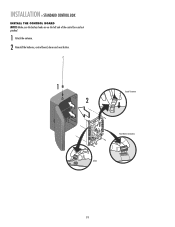
... screws to remove the control board and mounting bracket. 4 Remove the control board. 5 Remove batteries and set aside. 6 Select mounting holes and knock out using a screwdriver and hammer. 7 Secure the control box to mounting surface using the appropriate hardware (not provided). Knock Outs B. INSTALLATION » STANDARD CONTROL BOX MOUNT THE CONTROL BOX The control box MUST be mounted within 5 feet...
... screws to remove the control board and mounting bracket. 4 Remove the control board. 5 Remove batteries and set aside. 6 Select mounting holes and knock out using a screwdriver and hammer. 7 Secure the control box to mounting surface using the appropriate hardware (not provided). Knock Outs B. INSTALLATION » STANDARD CONTROL BOX MOUNT THE CONTROL BOX The control box MUST be mounted within 5 feet...
LA400 Manual
Page 20
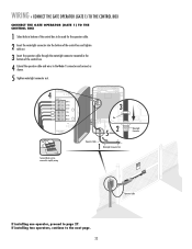
INSTALLATION » STANDARD CONTROL BOX INSTALL THE CONTROL BOARD NOTE: Make sure the battery leads are on the left side of the control box and not pinched. 1 Attach the antenna. 2 Reinstall the batteries, control board, alarm and reset button. 1 2 Coaxial Connector Reset Button Connections Alarm 19
INSTALLATION » STANDARD CONTROL BOX INSTALL THE CONTROL BOARD NOTE: Make sure the battery leads are on the left side of the control box and not pinched. 1 Attach the antenna. 2 Reinstall the batteries, control board, alarm and reset button. 1 2 Coaxial Connector Reset Button Connections Alarm 19
LA400 Manual
Page 21
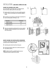
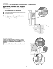
...ground rod with 'U' bolts. NOTE: The additional standoffs are specifically designed to mount up to one of the two green ground screws inside the control box. The knock out will accommodate a 3/8" diameter 'U' bolt. 2 Type and Size Standard 3" Round Pipe Standard 4" Square Post Standard 6" Square... Post 'U' Bolt Opening 3-1/2" 4" 6" 3 Select center mounting holes (top and bottom) knock out using a metal control box to prevent serious injury to persons or damage to install the ground rod when using a screwdriver and hammer. Ground Screw Standoffs ALARM LOCK...
...ground rod with 'U' bolts. NOTE: The additional standoffs are specifically designed to mount up to one of the two green ground screws inside the control box. The knock out will accommodate a 3/8" diameter 'U' bolt. 2 Type and Size Standard 3" Round Pipe Standard 4" Square Post Standard 6" Square... Post 'U' Bolt Opening 3-1/2" 4" 6" 3 Select center mounting holes (top and bottom) knock out using a metal control box to prevent serious injury to persons or damage to install the ground rod when using a screwdriver and hammer. Ground Screw Standoffs ALARM LOCK...

LA400 Manual
Page 22
... the 120 Vac access panel may be used to access the wiring. 3 Connect two 7AH batteries, purchased separately. The illustrations show the standard control box, not the XLM control box. 21 See Accessories page. INSTALLATION » LARGE METAL CONTROL BOX (XLM) WIRING 1 Select the knock out in the bottom of the receptacles is for the standard...
... the 120 Vac access panel may be used to access the wiring. 3 Connect two 7AH batteries, purchased separately. The illustrations show the standard control box, not the XLM control box. 21 See Accessories page. INSTALLATION » LARGE METAL CONTROL BOX (XLM) WIRING 1 Select the knock out in the bottom of the receptacles is for the standard...
LA400 Manual
Page 23
... can be used for the operator cable. 2 Insert the watertight connector into the bottom of the control box and tighten with nut. 3 Insert the operator cable through the watertight connector mounted in the bottom of the control box. 4 Extend the operator cable and wires to the next page. 22 Watertight Connector KtDpTPiMmlheEoaidEyseneoPoieswntnvtCirtttliLiehhrIaanEteonnncAusggjchtRauemiplt!GdeirursGriysoaeaaftrrnoteteuorwaoesmv.rapeereaChnsDryeiiacnapmtelgeean...
... can be used for the operator cable. 2 Insert the watertight connector into the bottom of the control box and tighten with nut. 3 Insert the operator cable through the watertight connector mounted in the bottom of the control box. 4 Extend the operator cable and wires to the next page. 22 Watertight Connector KtDpTPiMmlheEoaidEyseneoPoieswntnvtCirtttliLiehhrIaanEteonnncAusggjchtRauemiplt!GdeirursGriysoaeaaftrrnoteteuorwaoesmv.rapeereaChnsDryeiiacnapmtelgeean...

LA400 Manual
Page 24
...187; SET THE BIPART DELAY (MODEL LA400-S ONLY) SET THE BIPART DELAY (MODEL LA400-S ONLY) In some dual gate installations, one gate or if using a solenoid lock, for the control box, then mount the control box on the opposite side, but connect the operator closest to the control box to the Gate 1 connector. The ...) must be installed on the outside of the gate. The range is 0 to 8 seconds, 0 seconds is no appropriate location on that the control box be set as this gate. If there is OFF. Connect to Gate 1 Connector on the opposite side to the Gate 2 connector and 1 the...
...187; SET THE BIPART DELAY (MODEL LA400-S ONLY) SET THE BIPART DELAY (MODEL LA400-S ONLY) In some dual gate installations, one gate or if using a solenoid lock, for the control box, then mount the control box on the opposite side, but connect the operator closest to the control box to the Gate 1 connector. The ...) must be installed on the outside of the gate. The range is 0 to 8 seconds, 0 seconds is no appropriate location on that the control box be set as this gate. If there is OFF. Connect to Gate 1 Connector on the opposite side to the Gate 2 connector and 1 the...

LA400 Manual
Page 25
...; CONNECT THE GATE OPERATOR (GATE 2) TO THE CONTROL BOX (MODEL LA400-S ONLY) CONNECT THE GATE OPERATOR (GATE 2) TO THE CONTROL BOX (MODEL LA400-S ONLY) Before digging, contact local underground utility locating companies. 1 Trench across driveway to simplify wiring. Control Box PTpDtKiMhlmeEoadiEyseneoPioeswnnttvCirtttliLiherhaIantEeonnncAusggcjhtRaumeiptl!GdeirursGriysaoeaaftrronteuteorwaoesmv.rapeereaChsnDryeiiacnaptmelgeean.oasrtahvottCeeehnaglaeytanutaternsayonerce Gate Operator (Gate 2) Gate Operator (Gate 1) 1 Junction Box Extension Cable PVC conduit at least 18...
...; CONNECT THE GATE OPERATOR (GATE 2) TO THE CONTROL BOX (MODEL LA400-S ONLY) CONNECT THE GATE OPERATOR (GATE 2) TO THE CONTROL BOX (MODEL LA400-S ONLY) Before digging, contact local underground utility locating companies. 1 Trench across driveway to simplify wiring. Control Box PTpDtKiMhlmeEoadiEyseneoPioeswnnttvCirtttliLiherhaIantEeonnncAusggcjhtRaumeiptl!GdeirursGriysaoeaaftrronteuteorwaoesmv.rapeereaChsnDryeiiacnaptmelgeean.oasrtahvottCeeehnaglaeytanutaternsayonerce Gate Operator (Gate 2) Gate Operator (Gate 1) 1 Junction Box Extension Cable PVC conduit at least 18...
LA400 Manual
Page 28
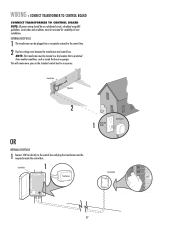
... Room 1 Conference Room 2 Comp. Local codes and conditions must be plugged into a receptacle external to the control box and plug the transformer into the receptacle inside the house or garage. Control Box 1 Transformer Circuit Panel Refer. This will create more space in a dry location that is protected from weather ...conditions, such as inside the control box. Serve 1 Off Off Off Off Off Off On On On On On On On On Off Off Off Off Off Off Off Off Air (1) Conditioner Main Room LA400 Bathroon. Eug. Manu. 1 Rm Main Dept. ...
... Room 1 Conference Room 2 Comp. Local codes and conditions must be plugged into a receptacle external to the control box and plug the transformer into the receptacle inside the house or garage. Control Box 1 Transformer Circuit Panel Refer. This will create more space in a dry location that is protected from weather ...conditions, such as inside the control box. Serve 1 Off Off Off Off Off Off On On On On On On On On Off Off Off Off Off Off Off Off Air (1) Conditioner Main Room LA400 Bathroon. Eug. Manu. 1 Rm Main Dept. ...
LA400 Manual
Page 29
...USE DEDICATED CIRCUIT 1 BATT 1 BATT 1 Connector BATT 2 Connector 28 The operator is a battery run system. Both batteries are the main source of the control board marked . The 24 Vac input can accept a charging transformer (26 Vac, 29 VA or 36 Vdc, 40 VA). 1 Connect the plugs from ...the batteries to the green screw on the outlet plate. ALARM MAGLOCK Z1 GATE 1 ACCESSORY POWER GATE 2 R4 J4 FUSE FUOSPEEN OPEN D15 C2 MOV2 Control Box R4 C2 J4 24 VAC/ SOLAR INPUT Ground Screw 12 Gauge Wire 3' (0.9 m) Earth Ground Installation (Optional) 8' (2.4 m) CONNECT BATTERIES The batteries...
...USE DEDICATED CIRCUIT 1 BATT 1 BATT 1 Connector BATT 2 Connector 28 The operator is a battery run system. Both batteries are the main source of the control board marked . The 24 Vac input can accept a charging transformer (26 Vac, 29 VA or 36 Vdc, 40 VA). 1 Connect the plugs from ...the batteries to the green screw on the outlet plate. ALARM MAGLOCK Z1 GATE 1 ACCESSORY POWER GATE 2 R4 J4 FUSE FUOSPEEN OPEN D15 C2 MOV2 Control Box R4 C2 J4 24 VAC/ SOLAR INPUT Ground Screw 12 Gauge Wire 3' (0.9 m) Earth Ground Installation (Optional) 8' (2.4 m) CONNECT BATTERIES The batteries...
LA400 Manual
Page 31
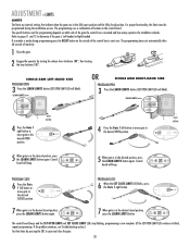
... Engage the operator by pressing the SBC to the desired CLOSED position. The specific buttons used for programming depends on which side of the control box to the desired OPEN position. LIMIT LIMIT 5 When gate is in the desired position, press the LEARN LIMITS button again. LEARN LIMITS button...position, press the LEARN LIMITS button. The programming times-out automatically after 60 seconds of buttons on the outside of the gate the control box is Left-handed or Right-handed. ADJUSTMENT » LIMITS LIMITS The limits are internal settings that indicate when the gates are in ...
... Engage the operator by pressing the SBC to the desired CLOSED position. The specific buttons used for programming depends on which side of the control box to the desired OPEN position. LIMIT LIMIT 5 When gate is in the desired position, press the LEARN LIMITS button again. LEARN LIMITS button...position, press the LEARN LIMITS button. The programming times-out automatically after 60 seconds of buttons on the outside of the gate the control box is Left-handed or Right-handed. ADJUSTMENT » LIMITS LIMITS The limits are internal settings that indicate when the gates are in ...
LA400 Manual
Page 37
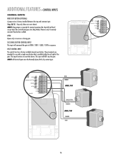
...CONTROL INPUT The control box has a factory installed internal reset button. Remove only if remotely mounted Stop button is added. NOTE: All Control Inputs must be lit except when the control board goes into Sleep Mode). Stop only (does not reset alarm). OPEN CONTROL INPUTS SINGLE BUTTON RESET STOP COM COM OPEN CONTROL... for use with a single reset button that is installed within line of sight of the gate. ADDITIONAL FEATURES » CONTROL INPUTS CONTROL INPUTS WIRE STOP BUTTON (OPTIONAL) A jumper wire is factory installed between the stop the gate. OPEN Opens only or...
...CONTROL INPUT The control box has a factory installed internal reset button. Remove only if remotely mounted Stop button is added. NOTE: All Control Inputs must be lit except when the control board goes into Sleep Mode). Stop only (does not reset alarm). OPEN CONTROL INPUTS SINGLE BUTTON RESET STOP COM COM OPEN CONTROL... for use with a single reset button that is installed within line of sight of the gate. ADDITIONAL FEATURES » CONTROL INPUTS CONTROL INPUTS WIRE STOP BUTTON (OPTIONAL) A jumper wire is factory installed between the stop the gate. OPEN Opens only or...

LA400 Manual
Page 39
... 24 Vac power supply. MODEL CPS-LN4 CPS-RN4 MODEL G65MG0204 G65MG0205 G65MGR205 G65MGS205 PHOTOELECTRIC CONTROLS DESCRIPTION Emitter, receiver and mounting brackets - 30 feet (9 m) Ranges VOLTAGE +24 Vdc Emitter with the LA400 to control box depending on wire gauge and distance - 300 mA accessory power, 75 mA switched accessory ... devices are acceptable for Safety Accessories for 2 inch (5 cm) square post. MAX CURRENT DRAW: • 115 Vac power to control box - 500 mA accessory power, 150 mA switched accessory power. • 24 V power to meet the requirements of UL325 and UL991.
... 24 Vac power supply. MODEL CPS-LN4 CPS-RN4 MODEL G65MG0204 G65MG0205 G65MGR205 G65MGS205 PHOTOELECTRIC CONTROLS DESCRIPTION Emitter, receiver and mounting brackets - 30 feet (9 m) Ranges VOLTAGE +24 Vdc Emitter with the LA400 to control box depending on wire gauge and distance - 300 mA accessory power, 75 mA switched accessory ... devices are acceptable for Safety Accessories for 2 inch (5 cm) square post. MAX CURRENT DRAW: • 115 Vac power to control box - 500 mA accessory power, 150 mA switched accessory power. • 24 V power to meet the requirements of UL325 and UL991.
LA400 Manual
Page 40
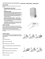
... lever. 3 Remove the key and store in the open position for normal daily operation and you can activate the Party Mode. Reset the control board by remote control or SBC on the outside of a power failure, the operator can be disengaged from the gate. OPERATION AND MAINTENANCE » RESET BUTTON ... been programmed operator will operate as follows: When gate is in the closed manually. MANUAL RELEASE In case of the control box and serves several functions. RELEASE 1 Insert the key into the lock. 2 Turn the key counter-clockwise 180°. 3 Turn the release lever counter-...
... lever. 3 Remove the key and store in the open position for normal daily operation and you can activate the Party Mode. Reset the control board by remote control or SBC on the outside of a power failure, the operator can be disengaged from the gate. OPERATION AND MAINTENANCE » RESET BUTTON ... been programmed operator will operate as follows: When gate is in the closed manually. MANUAL RELEASE In case of the control box and serves several functions. RELEASE 1 Insert the key into the lock. 2 Turn the key counter-clockwise 180°. 3 Turn the release lever counter-...

LA400 Manual
Page 44
... not programmed. 3) STOP connection loose/disconnected. 4) Constant Open Command (Check LED's). 5) Limits not programmed correctly. 6) Bad control board. 1) Low Battery. 2) Cable wiring between control box and operator arm disconnected or loose. 3) Batteries not connected. 4) Bad motor. 5) Bad control board. 1) Gate met an obstruction. 2) Force set . 2) Limits not programmed correctly. 3) Incorrect Arm Installation 1) Timer-to...
... not programmed. 3) STOP connection loose/disconnected. 4) Constant Open Command (Check LED's). 5) Limits not programmed correctly. 6) Bad control board. 1) Low Battery. 2) Cable wiring between control box and operator arm disconnected or loose. 3) Batteries not connected. 4) Bad motor. 5) Bad control board. 1) Gate met an obstruction. 2) Force set . 2) Limits not programmed correctly. 3) Incorrect Arm Installation 1) Timer-to...

LA400 Manual
Page 45
... 5 K74-19499 6 K74-30762 7 K74-30763 8 K76-19446 K74-30941 K001A5747-2 K001A5747 K76-35600 K76-35364 DESCRIPTION QTY Control Board 1 Control Box & Cover with Gasket 1 Control Board Bracket 1 Reset Switch 1 Antenna 1 Battery 2 Transformer 1 Alarm 1 Not Shown ATC Fuse Kit Includes 20 Amp (1),... 15 Amp (2) Receiver Module - 390 MHz Receiver Module - 315 MHz Reset Switch (XLM Control Box) Alarm (XLM Control Box) GATE OPERATOR ARM 22 33 ITEM PART # DESCRIPTION QTY 1 41ASWG-442SA Release Lever 1 2 41ASWG-438SA Motor with Limit 1 ...
... 5 K74-19499 6 K74-30762 7 K74-30763 8 K76-19446 K74-30941 K001A5747-2 K001A5747 K76-35600 K76-35364 DESCRIPTION QTY Control Board 1 Control Box & Cover with Gasket 1 Control Board Bracket 1 Reset Switch 1 Antenna 1 Battery 2 Transformer 1 Alarm 1 Not Shown ATC Fuse Kit Includes 20 Amp (1),... 15 Amp (2) Receiver Module - 390 MHz Receiver Module - 315 MHz Reset Switch (XLM Control Box) Alarm (XLM Control Box) GATE OPERATOR ARM 22 33 ITEM PART # DESCRIPTION QTY 1 41ASWG-442SA Release Lever 1 2 41ASWG-438SA Motor with Limit 1 ...


