8355 Manual
Page 1
PREMIUM Series Belt Drive Garage Door Opener Model 8355 - 1/2 hp FOR RESIDENTIAL USE ONLY ■ Please read this manual and the enclosed safety materials carefully! ■ Fasten the manual near the garage door after ... Features 27 Door Control 28-29 Remote Control 30-31 To Erase the Memory 31 To Open the Door Manually . . . . . 32 Maintenance 32 Troubleshooting 33-34 Accessories 35 Warranty 36 Repair Parts 37-38 www.liftmaster.com The Chamberlain Group, Inc. 845 Larch Avenue Elmhurst, Illinois 60126-1196 Write down the following...
PREMIUM Series Belt Drive Garage Door Opener Model 8355 - 1/2 hp FOR RESIDENTIAL USE ONLY ■ Please read this manual and the enclosed safety materials carefully! ■ Fasten the manual near the garage door after ... Features 27 Door Control 28-29 Remote Control 30-31 To Erase the Memory 31 To Open the Door Manually . . . . . 32 Maintenance 32 Troubleshooting 33-34 Accessories 35 Warranty 36 Repair Parts 37-38 www.liftmaster.com The Chamberlain Group, Inc. 845 Larch Avenue Elmhurst, Illinois 60126-1196 Write down the following...
8355 Manual
Page 2
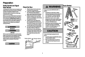
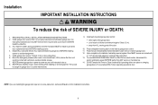
.... The hazard may not work properly. 5. See page 7. Read them . Preparation Safety Symbol and Signal Word Review This garage door opener has been designed and tested to offer safe service provided it is installed, operated, maintained and tested in strict accordance with the instructions ...and warnings contained in place, supported entirely by its springs. 3. The opener should stay in this Signal Word on the bottom of balance, call a trained door systems technician if garage door binds, sticks, or...
.... The hazard may not work properly. 5. See page 7. Read them . Preparation Safety Symbol and Signal Word Review This garage door opener has been designed and tested to offer safe service provided it is installed, operated, maintained and tested in strict accordance with the instructions ...and warnings contained in place, supported entirely by its springs. 3. The opener should stay in this Signal Word on the bottom of balance, call a trained door systems technician if garage door binds, sticks, or...
8355 Manual
Page 3
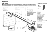
...B CF G D E F. Trolley G. Emergency release rope and handle H. White and red/white wire N. Garage door opener K J. The Protector System® Safety reversing sensors with hex screws K. The instructions for reference and your product may ...other accessories may look different. Pulley and bracket C. Depending on the garage door opener model purchased. A. Curved door arm E. Belt L. Preparation Carton Inventory NOTE: Accessories will be included with your garage door opener. The images throughout this manual. Header bracket B. Door bracket D. Rail I...
...B CF G D E F. Trolley G. Emergency release rope and handle H. White and red/white wire N. Garage door opener K J. The Protector System® Safety reversing sensors with hex screws K. The instructions for reference and your product may ...other accessories may look different. Pulley and bracket C. Depending on the garage door opener model purchased. A. Curved door arm E. Belt L. Preparation Carton Inventory NOTE: Accessories will be included with your garage door opener. The images throughout this manual. Header bracket B. Door bracket D. Rail I...

8355 Manual
Page 4
...Bolt 5/16"-18x1/2" (Mounted in the top of the opener. Lock Nut (Mounted in the garage door opener) Hex Screw #8x3/8" (Packed with the previously removed bolts. Place the garage door opener on the packing material to garage door opener, use ONLY those bolts/fasteners mounted in the garage door... opener) NOTE: ONLY use the bolts removed from the garage door opener. Cut the tape from the top of sprocket while operating opener. • Securely attach ...
...Bolt 5/16"-18x1/2" (Mounted in the top of the opener. Lock Nut (Mounted in the garage door opener) Hex Screw #8x3/8" (Packed with the previously removed bolts. Place the garage door opener on the packing material to garage door opener, use ONLY those bolts/fasteners mounted in the garage door... opener) NOTE: ONLY use the bolts removed from the garage door opener. Cut the tape from the top of sprocket while operating opener. • Securely attach ...

8355 Manual
Page 5
Do not use any tools. (To motor unit) Spring Trolley Nut Nut ring slot 2.3 Tighten the spring trolley nut with an adjustable wrench or a 7/16" open end wrench about a quarter turn until it is finger tight against 2.2 Insert a flathead screwdriver tip into one of the nut ring slots and brace it ...
Do not use any tools. (To motor unit) Spring Trolley Nut Nut ring slot 2.3 Tighten the spring trolley nut with an adjustable wrench or a 7/16" open end wrench about a quarter turn until it is finger tight against 2.2 Insert a flathead screwdriver tip into one of the nut ring slots and brace it ...
8355 Manual
Page 6
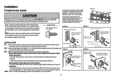
... doors. ALL repairs to avoid accidental release. 7. Disable ALL locks and remove ALL ropes connected to garage door BEFORE installing opener to do so. 8. To be enabled ONLY when operating a sectional door. Installation IMPORTANT INSTALLATION INSTRUCTIONS WARNING To reduce the risk...or loose clothing while installing or servicing opener. Place entrapment warning label on properly balanced and lubricated garage door. Install garage door opener ONLY on wall next to -Close functionality if operating either one -piece door, visit www.liftmaster.com for installation instructions. 6
... doors. ALL repairs to avoid accidental release. 7. Disable ALL locks and remove ALL ropes connected to garage door BEFORE installing opener to do so. 8. To be enabled ONLY when operating a sectional door. Installation IMPORTANT INSTALLATION INSTRUCTIONS WARNING To reduce the risk...or loose clothing while installing or servicing opener. Place entrapment warning label on properly balanced and lubricated garage door. Install garage door opener ONLY on wall next to -Close functionality if operating either one -piece door, visit www.liftmaster.com for installation instructions. 6
8355 Manual
Page 7
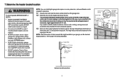
... Header Wall 2" (5 cm) Track Highest Point of Travel Door Unfinished Ceiling Header Wall 2x4 Vertical Centerline of which are installing the garage door opener on a one -piece or swinging garage doors. 1 Determine the header bracket location To prevent possible SERIOUS INJURY or DEATH: • Header ... NOT reverse when required. • DO NOT enable the Timer-to-Close functionality if operating either one -piece door, visit www.liftmaster.com for ceiling installation. DO NOT install header bracket over drywall. • Concrete anchors MUST be used if mounting header bracket or...
... Header Wall 2" (5 cm) Track Highest Point of Travel Door Unfinished Ceiling Header Wall 2x4 Vertical Centerline of which are installing the garage door opener on a one -piece or swinging garage doors. 1 Determine the header bracket location To prevent possible SERIOUS INJURY or DEATH: • Header ... NOT reverse when required. • DO NOT enable the Timer-to-Close functionality if operating either one -piece door, visit www.liftmaster.com for ceiling installation. DO NOT install header bracket over drywall. • Concrete anchors MUST be used if mounting header bracket or...
8355 Manual
Page 9
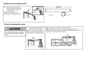
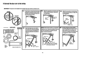
... through the holes in the header bracket and rail. NOTE: A 2x4 is not tall enough you will need help at this point. 4.2 Fully open the door and place a 2x4 (laid flat) under the rail. NOTE: If the door hits the trolley when it is raised, pull the ... the rail with the ring fastener. Connected Disconnected 9 Ring Fastener Clevis Pin 5/16" X 2-3/4" HARDWARE Clevis Pin 5/16" x 2-3/4" Ring Fastener 4 Position the garage door opener To prevent damage to disconnect the inner and outer trolley. NOTE: Use the packing material as a protective base for setting the distance between the rail...
... through the holes in the header bracket and rail. NOTE: A 2x4 is not tall enough you will need help at this point. 4.2 Fully open the door and place a 2x4 (laid flat) under the rail. NOTE: If the door hits the trolley when it is raised, pull the ... the rail with the ring fastener. Connected Disconnected 9 Ring Fastener Clevis Pin 5/16" X 2-3/4" HARDWARE Clevis Pin 5/16" x 2-3/4" Ring Fastener 4 Position the garage door opener To prevent damage to disconnect the inner and outer trolley. NOTE: Use the packing material as a protective base for setting the distance between the rail...
8355 Manual
Page 10
...the structural supports. 5.4 Attach one end of the garage. Hanging brackets should be angled (Figure 1) to structural supports before installing the opener. On finished ceilings (Figure 2), attach a sturdy metal bracket to provide rigid support. Concrete anchors MUST be different. HARDWARE Lock Washer ...5/16" Hex Bolt 5/16"- 18x7/8" Hanging your garage door opener will vary depending on your garage. Operate the door manually. NOTE: DO NOT connect power to required lengths. 5.3 Drill 3/16"...
...the structural supports. 5.4 Attach one end of the garage. Hanging brackets should be angled (Figure 1) to structural supports before installing the opener. On finished ceilings (Figure 2), attach a sturdy metal bracket to provide rigid support. Concrete anchors MUST be different. HARDWARE Lock Washer ...5/16" Hex Bolt 5/16"- 18x7/8" Hanging your garage door opener will vary depending on your garage. Operate the door manually. NOTE: DO NOT connect power to required lengths. 5.3 Drill 3/16"...

8355 Manual
Page 11
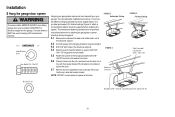
... rope. 7.2 Insert the other end of the emergency release rope through the handle. performance of the emergency release rope through the hole in an open or closed. Weak or broken springs or unbalanced door could fall. 7.1 Insert one end of your remote control(s). 6.3 Rotate the lens up ...or compact fluorescent (26W, 100W equivalent) light bulb into the light socket. Make sure that "NOTICE" is right side up to pull door open door falling rapidly and/or unexpectedly. • NEVER use emergency release handle unless garage doorway is CLOSED. Ensure the emergency release rope and ...
... rope. 7.2 Insert the other end of the emergency release rope through the handle. performance of the emergency release rope through the hole in an open or closed. Weak or broken springs or unbalanced door could fall. 7.1 Insert one end of your remote control(s). 6.3 Rotate the lens up ...or compact fluorescent (26W, 100W equivalent) light bulb into the light socket. Make sure that "NOTICE" is right side up to pull door open door falling rapidly and/or unexpectedly. • NEVER use emergency release handle unless garage doorway is CLOSED. Ensure the emergency release rope and ...
8355 Manual
Page 12
... and install as the horizontal brace. Installation 8 Install the door bracket A horizontal and vertical reinforcement is to check with your garage door manufacturer for an opener installation door reinforcement kit.
... and install as the horizontal brace. Installation 8 Install the door bracket A horizontal and vertical reinforcement is to check with your garage door manufacturer for an opener installation door reinforcement kit.
8355 Manual
Page 13
... Clevis Pin 5/16"x1" Ring Fastener 9.4 Align the straight door arm with the ring fastener. trolley will re-engage automatically when the garage door opener is hanging down too far, you may cut 6 inches (15 cm) from the curved door arm. Select two aligned holes (as far apart ...5/16" x 1" 9.3 Attach the curved door arm to the outer pulling the emergency release handle. Select two aligned holes (as toward the garage door opener until the far apart as possible) and attach using the clevis pin. 9 Connect the door arm to the trolley IMPORTANT: The groove on the straight...
... Clevis Pin 5/16"x1" Ring Fastener 9.4 Align the straight door arm with the ring fastener. trolley will re-engage automatically when the garage door opener is hanging down too far, you may cut 6 inches (15 cm) from the curved door arm. Select two aligned holes (as far apart ...5/16" x 1" 9.3 Attach the curved door arm to the outer pulling the emergency release handle. Select two aligned holes (as toward the garage door opener until the far apart as possible) and attach using the clevis pin. 9 Connect the door arm to the trolley IMPORTANT: The groove on the straight...
8355 Manual
Page 14
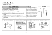
...(1.5 m), and away from the moving parts of the door the illustrations. on the back of the wire and separate the wires. NOTE: Older LiftMaster door controls To prevent possible SERIOUS INJURY or DEATH from 1.2 Connect one wire to each of the two screws 1.3 Mark the location of the bottom...holes in the gang box. 1.1 Strip 7/16 inch (11 mm) of insulation from a closing garage door. accessories, see page 37. Your garage door opener is compatible with MyQ® and Security+ 2.0™ To prevent possible SERIOUS INJURY or DEATH from the wall. DRYWALL Drywall Anchor Screw 6AB x 1" GANG...
...(1.5 m), and away from the moving parts of the door the illustrations. on the back of the wire and separate the wires. NOTE: Older LiftMaster door controls To prevent possible SERIOUS INJURY or DEATH from 1.2 Connect one wire to each of the two screws 1.3 Mark the location of the bottom...holes in the gang box. 1.1 Strip 7/16 inch (11 mm) of insulation from a closing garage door. accessories, see page 37. Your garage door opener is compatible with MyQ® and Security+ 2.0™ To prevent possible SERIOUS INJURY or DEATH from the wall. DRYWALL Drywall Anchor Screw 6AB x 1" GANG...
8355 Manual
Page 15
...RED WHITE WHITE GREY PRE-WIRED INSTALLATIONS: When wiring the door control to the garage door opener make sure you use the same wires that are connected to the wall and ceiling with ... from the terminal, push in the tab with the staple as this may cause a short or an open circuit. 2.2 Strip 7/16 inch (11 mm) of insulation from the door control to the red and white terminals on... the garage door opener. Do not pierce the wire with screwdriver tip. Attach the top screw. Attach the wire to the door control...
...RED WHITE WHITE GREY PRE-WIRED INSTALLATIONS: When wiring the door control to the garage door opener make sure you use the same wires that are connected to the wall and ceiling with ... from the terminal, push in the tab with the staple as this may cause a short or an open circuit. 2.2 Strip 7/16 inch (11 mm) of insulation from the door control to the red and white terminals on... the garage door opener. Do not pierce the wire with screwdriver tip. Attach the top screw. Attach the wire to the door control...
8355 Manual
Page 17
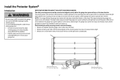
This required safety device MUST NOT be connected and aligned correctly before the garage door opener will turn off the sensor LEDs will move in the down until the garage door opener has completed 5 cycles upon power up. Install the Protector System® Introduction Be sure power is... prevent SERIOUS INJURY or DEATH from closing , the door will stop and reverse to the garage door opener BEFORE installing the safety reversing sensor. NOTE: For energy efficiency the garage door opener will flash 10 times. Safety Reversing Sensor 6" (15 cm) max. The sleep mode is unobstructed...
This required safety device MUST NOT be connected and aligned correctly before the garage door opener will turn off the sensor LEDs will move in the down until the garage door opener has completed 5 cycles upon power up. Install the Protector System® Introduction Be sure power is... prevent SERIOUS INJURY or DEATH from closing , the door will stop and reverse to the garage door opener BEFORE installing the safety reversing sensor. NOTE: For energy efficiency the garage door opener will flash 10 times. Safety Reversing Sensor 6" (15 cm) max. The sleep mode is unobstructed...

8355 Manual
Page 19
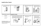
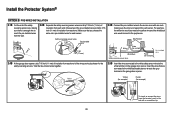
... sensor bracket and attach with the wing nut. Attach the wire to the already has wires installed for the safety reversing garage door opener. the wall and ceiling with a screwdriver tip. Insert the white/black wires into the slot on each sensor. The lens on the garage... brackets to the floor using concrete anchors (not provided). (not provided) IGWnsaairdlalege 1.3C Slide the carriage bolt into the grey terminal on the garage door opener. RED WHITE WHITE GREY Insulated Staple (Not shown) 7/16" (11 mm) 19 Carriage Bolt 1/4" - 20 x 1/2" 1.4C Insert the bolt through the hole ...
... sensor bracket and attach with the wing nut. Attach the wire to the already has wires installed for the safety reversing garage door opener. the wall and ceiling with a screwdriver tip. Insert the white/black wires into the slot on each sensor. The lens on the garage... brackets to the floor using concrete anchors (not provided). (not provided) IGWnsaairdlalege 1.3C Slide the carriage bolt into the grey terminal on the garage door opener. RED WHITE WHITE GREY Insulated Staple (Not shown) 7/16" (11 mm) 19 Carriage Bolt 1/4" - 20 x 1/2" 1.4C Insert the bolt through the hole ...
8355 Manual
Page 20
... (for the safety reversing sensors. Make sure that are connected to the white/black safety sensor wires to the grey terminal on the garage door opener. Safety reversing sensor wires 7/16" (11 mm) Pre-installed wires 7/16" (11 mm) 2.3B Connect the pre-installed wires to the white ...terminal on the garage door opener. Twist the like-colored wires together. 2.5B Insert the wires connected to the white safety sensor wires to the sensor wires with a screwdriver tip. 20...
... (for the safety reversing sensors. Make sure that are connected to the white/black safety sensor wires to the grey terminal on the garage door opener. Safety reversing sensor wires 7/16" (11 mm) Pre-installed wires 7/16" (11 mm) 2.3B Connect the pre-installed wires to the white ...terminal on the garage door opener. Twist the like-colored wires together. 2.5B Insert the wires connected to the white safety sensor wires to the sensor wires with a screwdriver tip. 20...
8355 Manual
Page 21
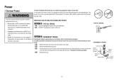
...the green ground screw. To prevent possible SERIOUS INJURY or DEATH from electrocution or fire: • Be sure power is NOT connected to the opener, and disconnect power to circuit BEFORE removing cover to the screw on the silver terminal; THERE ARE TWO OPTIONS FOR CONNECTING POWER: OPTION A...a third grounding pin. TYPICAL WIRING PERMANENT WIRING Ground Tab Green Ground Screw Ground Wire White Wire Black Wire Black Wire 21 Be sure the opener is required by your local code, refer to the screw on the brass terminal; the white (neutral) wire to the following procedure. To...
...the green ground screw. To prevent possible SERIOUS INJURY or DEATH from electrocution or fire: • Be sure power is NOT connected to the opener, and disconnect power to circuit BEFORE removing cover to the screw on the silver terminal; THERE ARE TWO OPTIONS FOR CONNECTING POWER: OPTION A...a third grounding pin. TYPICAL WIRING PERMANENT WIRING Ground Tab Green Ground Screw Ground Wire White Wire Black Wire Black Wire 21 Be sure the opener is required by your local code, refer to the screw on the brass terminal; the white (neutral) wire to the following procedure. To...
8355 Manual
Page 22
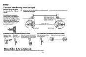
... power to grey terminal. Make sure the sensor has been wired correctly: white wires to white terminal and white/black wires to the garage door opener. IF THE GREEN LED ON THE RECEIVING SENSOR IS NOT GLOWING: Make sure the sensor wire is closing, the door will reverse and the garage... will flash ten times. RED WHITE WHITE GREY 3 Ensure the Door Control is not shorted/broken. If the door is already open, it is on the opposite side of the door. (invisible light beam) Green LED SENDING SENSOR RECEIVING SENSOR IF THE AMBER LED ON THE SENDING ...
... power to grey terminal. Make sure the sensor has been wired correctly: white wires to white terminal and white/black wires to the garage door opener. IF THE GREEN LED ON THE RECEIVING SENSOR IS NOT GLOWING: Make sure the sensor wire is closing, the door will reverse and the garage... will flash ten times. RED WHITE WHITE GREY 3 Ensure the Door Control is not shorted/broken. If the door is already open, it is on the opposite side of the door. (invisible light beam) Green LED SENDING SENSOR RECEIVING SENSOR IF THE AMBER LED ON THE SENDING ...
8355 Manual
Page 23
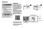
...will reverse. PROGRAMMING BUTTONS The programming buttons are located on floor. The adjustments allow you program the travel . 23 UP (Open) DOWN (Close) PROGRAMMING BUTTONS UP Button Adjustment Button DOWN Button If anything interferes with the door's downward travel, it will stop in ...; Incorrect adjustment of garage door travel limits will interfere with electronic controls to make setup and adjustments easy. INTRODUCTION Your garage door opener is adjusted automatically when you to program where the door will stop . The electronic controls sense the amount of force required to ...
...will reverse. PROGRAMMING BUTTONS The programming buttons are located on floor. The adjustments allow you program the travel . 23 UP (Open) DOWN (Close) PROGRAMMING BUTTONS UP Button Adjustment Button DOWN Button If anything interferes with the door's downward travel, it will stop in ...; Incorrect adjustment of garage door travel limits will interfere with electronic controls to make setup and adjustments easy. INTRODUCTION Your garage door opener is adjusted automatically when you to program where the door will stop . The electronic controls sense the amount of force required to ...


