8355 Manual
Page 3
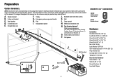
... (2) Wing Nut 1/4"-20 (2) Door Control Hardware Screw 6AB x 1" (2) Screw 6-32 x 1" (2) Drywall Anchors (2) Insulated Staples 3 Sprocket cover with white and white/black wire attached: Sending Sensor (1) Receiving Sensor (1) and Safety Sensor Brackets (2) O. The images throughout this manual. Pulley and bracket C. Garage door opener K J. Safety labels and literature P....Depending on the garage door opener model purchased. Emergency release rope and handle H. Belt L. White and red/white wire N. The Protector System® Safety reversing sensors with hex screws K.
... (2) Wing Nut 1/4"-20 (2) Door Control Hardware Screw 6AB x 1" (2) Screw 6-32 x 1" (2) Drywall Anchors (2) Insulated Staples 3 Sprocket cover with white and white/black wire attached: Sending Sensor (1) Receiving Sensor (1) and Safety Sensor Brackets (2) O. The images throughout this manual. Pulley and bracket C. Garage door opener K J. Safety labels and literature P....Depending on the garage door opener model purchased. Emergency release rope and handle H. Belt L. White and red/white wire N. The Protector System® Safety reversing sensors with hex screws K.
8355 Manual
Page 14
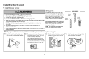
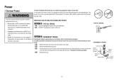
...feet (1.5 m), and away from ALL moving parts of door. NEVER permit anyone to cross path of moving parts of the door control. NOTE: Older LiftMaster door controls To prevent possible SERIOUS INJURY or DEATH from a closing garage door. Screw 6ABx1" Screw 6-32x1" HARDWARE Drywall Anchors NOTE: For gang ...box installations it can be seen clearly, is NOT connected BEFORE installing door control. • Connect ONLY to 12 VOLT low voltage wires. Install the door control within sight of garage door, out of reach of children at the garage door opener in a later step. 1.4 ...
...feet (1.5 m), and away from ALL moving parts of door. NEVER permit anyone to cross path of moving parts of the door control. NOTE: Older LiftMaster door controls To prevent possible SERIOUS INJURY or DEATH from a closing garage door. Screw 6ABx1" Screw 6-32x1" HARDWARE Drywall Anchors NOTE: For gang ...box installations it can be seen clearly, is NOT connected BEFORE installing door control. • Connect ONLY to 12 VOLT low voltage wires. Install the door control within sight of garage door, out of reach of children at the garage door opener in a later step. 1.4 ...
8355 Manual
Page 15
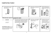
... open circuit. 2.2 Strip 7/16 inch (11 mm) of insulation from the wall and drill a 5/32 inch (4 mm) hole for gang box or pre-wired installations). Attach the wire to the garage door opener. Staple 15 Install the Door Control k 1.5 Position the bottom hole of the door control over the screw and slide... top hole. 1.7 Remove the door control from the end of the door control over the screw and slide down into place. To insert or release wires from the door control to the wall and ceiling with screwdriver tip. DRYWALL Drywall Anchor Screw 6AB x 1" Screw 6-32 x 1" GANG BOX...
... open circuit. 2.2 Strip 7/16 inch (11 mm) of insulation from the wall and drill a 5/32 inch (4 mm) hole for gang box or pre-wired installations). Attach the wire to the garage door opener. Staple 15 Install the Door Control k 1.5 Position the bottom hole of the door control over the screw and slide... top hole. 1.7 Remove the door control from the end of the door control over the screw and slide down into place. To insert or release wires from the door control to the wall and ceiling with screwdriver tip. DRYWALL Drywall Anchor Screw 6AB x 1" Screw 6-32 x 1" GANG BOX...

8355 Manual
Page 19
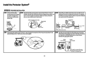
...on each other. Make sure the lens is not obstructed by the sensor bracket. Attach the wire to sensors, see page 20. Twist the white wires together. To insert or remove the wires from the wall and unobstructed. 1.2C Attach the sensor brackets to the floor using concrete anchors ... the slot on the garage door opener. Separate the wires. the wall and ceiling with the staples. Wing Nut 1/4" - 20 2 Wire the Safety Reversing Sensors OPTION A INSTALLATION WITHOUT PRE-WIRING PRE-WIRED INSTALLATIONS: If your garage 2.1A Run the wire from both sensor brackets so they will be the same...
...on each other. Make sure the lens is not obstructed by the sensor bracket. Attach the wire to sensors, see page 20. Twist the white wires together. To insert or remove the wires from the wall and unobstructed. 1.2C Attach the sensor brackets to the floor using concrete anchors ... the slot on the garage door opener. Separate the wires. the wall and ceiling with the staples. Wing Nut 1/4" - 20 2 Wire the Safety Reversing Sensors OPTION A INSTALLATION WITHOUT PRE-WIRING PRE-WIRED INSTALLATIONS: If your garage 2.1A Run the wire from both sensor brackets so they will be the same...
8355 Manual
Page 20
...) of insulation from each end. Insert the wires that you choose the same color pre-installed wires for each end. For example, the white wire would connect to the yellow wire and the white/black wire would connect to the sensor wires with a screwdriver tip. 20 Yellow Purple Yellow...sensors. Safety reversing sensor wires 7/16" (11 mm) Pre-installed wires 7/16" (11 mm) 2.3B Connect the pre-installed wires to the purple wire. Twist the like-colored wires together. 2.5B Insert the wires connected to the white safety sensor wires to reach the pre-installed wires from the wall. 2....
...) of insulation from each end. Insert the wires that you choose the same color pre-installed wires for each end. For example, the white wire would connect to the yellow wire and the white/black wire would connect to the sensor wires with a screwdriver tip. 20 Yellow Purple Yellow...sensors. Safety reversing sensor wires 7/16" (11 mm) Pre-installed wires 7/16" (11 mm) 2.3B Connect the pre-installed wires to the purple wire. Twist the like-colored wires together. 2.5B Insert the wires connected to the white safety sensor wires to reach the pre-installed wires from the wall. 2....
8355 Manual
Page 21
...): 1.1B Remove the motor unit cover screws and set the cover aside. 1.2B Remove the attached 3-prong cord. 1.3B Connect the black (line) wire to the screw on the silver terminal; This plug will only fit into a grounded outlet. 1.2A DO NOT run garage door opener at this time...doesn't fit into your garage door opener has a grounding type plug with ALL local electrical and building codes. • NEVER use an extension cord, 2-wire adapter, or change plug in the top of electric shock, your outlet, contact a qualified electrician to the screw on the brass terminal; To prevent possible...
...): 1.1B Remove the motor unit cover screws and set the cover aside. 1.2B Remove the attached 3-prong cord. 1.3B Connect the black (line) wire to the screw on the silver terminal; This plug will only fit into a grounded outlet. 1.2A DO NOT run garage door opener at this time...doesn't fit into your garage door opener has a grounding type plug with ALL local electrical and building codes. • NEVER use an extension cord, 2-wire adapter, or change plug in the top of electric shock, your outlet, contact a qualified electrician to the screw on the brass terminal; To prevent possible...
8355 Manual
Page 22
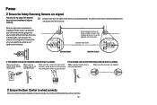
...the sensors, and tightening the wing nuts. Make sure the sensor wire is wired correctly If the door control has been installed and wired correctly, the command LED behind the push bar will blink. 22 Make sure the sensors are aligned and wired correctly. RED WHITE WHITE GREY 3 Ensure the Door Control is ... Reversing Sensors are aligned The door will not close . IF THE GREEN LED ON THE RECEIVING SENSOR IS NOT GLOWING: Make sure the sensor wire is closing, the door will reverse and the garage door opener lights will glow steadily if they are aligned. The LEDs in both sensors will...
...the sensors, and tightening the wing nuts. Make sure the sensor wire is wired correctly If the door control has been installed and wired correctly, the command LED behind the push bar will blink. 22 Make sure the sensors are aligned and wired correctly. RED WHITE WHITE GREY 3 Ensure the Door Control is ... Reversing Sensors are aligned The door will not close . IF THE GREEN LED ON THE RECEIVING SENSOR IS NOT GLOWING: Make sure the sensor wire is closing, the door will reverse and the garage door opener lights will glow steadily if they are aligned. The LEDs in both sensors will...
8355 Manual
Page 33
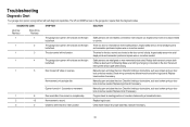
... Opener hums for a disconnected or cut . Inspect safety sensor wire at all staple points and connection points and replace wire or correct as needed . Inspect safety sensor wire at all staple points and connection points and replace wire or correct as needed . Safety sensors are steady and not flickering...it has come to set the travel or retain position. No movement or sound. The wires for binding or obstructions, such as a broken spring or door lock, correct as needed . Check wiring connections at the logic board. The garage door opener will not close the door. ...
... Opener hums for a disconnected or cut . Inspect safety sensor wire at all staple points and connection points and replace wire or correct as needed . Inspect safety sensor wire at all staple points and connection points and replace wire or correct as needed . Safety sensors are steady and not flickering...it has come to set the travel or retain position. No movement or sound. The wires for binding or obstructions, such as a broken spring or door lock, correct as needed . Check wiring connections at the logic board. The garage door opener will not close the door. ...
8355 Manual
Page 35
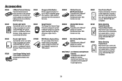
... in the garage. SECURITY✚ 2.0™ compatible. 35 present. 890MAX Mini 3-Button MAX Remote Control: Compatible with LiftMaster® garage door openers manufactured since 1993. SECURITY✚ 2.0™ compatible. Easy to precisely park vehicles in the ...the garage. Simply replaces your current wired wall switch. 990LM 825LM Remote Light Control: Automatically control your lights using your garage door opener, a SECURITY✚ 2.0™ remote control or a LiftMaster® Internet Gateway. Works with LiftMaster® garage door openers manufactured since...
... in the garage. SECURITY✚ 2.0™ compatible. 35 present. 890MAX Mini 3-Button MAX Remote Control: Compatible with LiftMaster® garage door openers manufactured since 1993. SECURITY✚ 2.0™ compatible. Easy to precisely park vehicles in the ...the garage. Simply replaces your current wired wall switch. 990LM 825LM Remote Light Control: Automatically control your lights using your garage door opener, a SECURITY✚ 2.0™ remote control or a LiftMaster® Internet Gateway. Works with LiftMaster® garage door openers manufactured since...
8355 Manual
Page 37
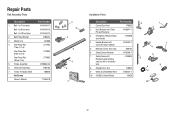
... and Fastener 41A4353-1 5 Remote Control Visor Clip 29B137 6 Safety Sensor Bracket 41A5266-1 7 Safety Sensor Kit Receiving and sending sensors with 2-conductor wire 41A5034 8 Straight Door Arm 178B34 9 White and Red/White Wire 41B4494-1 10 3V2032 Lithium Battery 10A20 3 1 2 7 4 6 8 5 9 10 37 for 7 foot door Belt - Repair Parts Rail Assembly Parts Description 1 Belt - for...
... and Fastener 41A4353-1 5 Remote Control Visor Clip 29B137 6 Safety Sensor Bracket 41A5266-1 7 Safety Sensor Kit Receiving and sending sensors with 2-conductor wire 41A5034 8 Straight Door Arm 178B34 9 White and Red/White Wire 41B4494-1 10 3V2032 Lithium Battery 10A20 3 1 2 7 4 6 8 5 9 10 37 for 7 foot door Belt - Repair Parts Rail Assembly Parts Description 1 Belt - for...
8355 Manual
Page 38
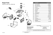
..., Inc. Tucson, AZ 85706 For installation and service information call: 1-800-528-9131 Or visit us online at: www.liftmaster.com Before calling, please have access to : The Chamberlain Group, Inc. 6050 S. MODEL 8355 4 3 15 14 6 7 13 114A4419E 1 2 10 8 11 5 9 6 7 12 Description 1 Cover with Screws ... Bracket 10 Terminal Block 11 Motor 12 Travel Module 13 Cover 14 Logic Board 15 Logic Board End Panel Not Shown Dual Wire Harness Kit Part Number 41A4371 41A4885-5 41A2817 41B4245 41A7756 41C279 41A7562 30B532 12A373 41A3150 41A7442 41D7742-7 41A7619-5 45ACT 41D216 41A7790 Contact...
..., Inc. Tucson, AZ 85706 For installation and service information call: 1-800-528-9131 Or visit us online at: www.liftmaster.com Before calling, please have access to : The Chamberlain Group, Inc. 6050 S. MODEL 8355 4 3 15 14 6 7 13 114A4419E 1 2 10 8 11 5 9 6 7 12 Description 1 Cover with Screws ... Bracket 10 Terminal Block 11 Motor 12 Travel Module 13 Cover 14 Logic Board 15 Logic Board End Panel Not Shown Dual Wire Harness Kit Part Number 41A4371 41A4885-5 41A2817 41B4245 41A7756 41C279 41A7562 30B532 12A373 41A3150 41A7442 41D7742-7 41A7619-5 45ACT 41D216 41A7790 Contact...

