
3950 Addendum Manual
Page 1
... SHAFT DOOR - ADDENDUM DOOR COMPATIBILITY FOR MODEL 3950 IMPORTANT INSTALLATION INSTRUCTIONS It is opened or closed. NOTE: The inside mounting option takes away from clear door opening. Rotating Axle Fixed Axle Live Shaft Door Figure 1 - Door Type Identification Dead Shaft Door Inside bracket...the drum and door assembly when the door is important to identify the door type before attempting an installation of the Model 3950 door operator. LIVE OR DEAD SHAFT DOOR IDENTIFICATION LIVE SHAFT DOOR - To order visit www.liftmaster.com or contact door supplier. MOUNTING OPTIONS...
... SHAFT DOOR - ADDENDUM DOOR COMPATIBILITY FOR MODEL 3950 IMPORTANT INSTALLATION INSTRUCTIONS It is opened or closed. NOTE: The inside mounting option takes away from clear door opening. Rotating Axle Fixed Axle Live Shaft Door Figure 1 - Door Type Identification Dead Shaft Door Inside bracket...the drum and door assembly when the door is important to identify the door type before attempting an installation of the Model 3950 door operator. LIVE OR DEAD SHAFT DOOR IDENTIFICATION LIVE SHAFT DOOR - To order visit www.liftmaster.com or contact door supplier. MOUNTING OPTIONS...

3950 Addendum Manual
Page 2
...amount of shaft is held up by the Model 3950 driving a chain which spins the drums and rolls the door curtain. The assembly is required (2.5" recommended) for the Model 3950. Live Shaft Clearances Minimum Shaft Length Past Door Bracket A minimum of 1.5" of side room ...- The door sprocket is attached to the outside of 3.75" clearance for "Wall" dimension is required to the door axle which spans the drive sprocket and the door sprocket. If inside mounted, minimum of the door opening. LIVE SHAFT REQUIREMENTS Live Shaft doors are automated by door brackets and the door guides. ...
...amount of shaft is held up by the Model 3950 driving a chain which spins the drums and rolls the door curtain. The assembly is required (2.5" recommended) for the Model 3950. Live Shaft Clearances Minimum Shaft Length Past Door Bracket A minimum of 1.5" of side room ...- The door sprocket is attached to the outside of 3.75" clearance for "Wall" dimension is required to the door axle which spans the drive sprocket and the door sprocket. If inside mounted, minimum of the door opening. LIVE SHAFT REQUIREMENTS Live Shaft doors are automated by door brackets and the door guides. ...

3950 Addendum Manual
Page 5
...Clearance Figure 6 - Dead Shaft Door Offset Drum Condition The door drum on the side on the mounting option for the Model 3950. Dead Shaft Door brackets should be considered if they interfere with operator installation. For a standard wall mount to the outside of the door opening, a minimum of side room ...depends on which the Model 3950 is required for the operator, however, the door brackets must not be bent or damaged in order for the desired operator mounting ...
...Clearance Figure 6 - Dead Shaft Door Offset Drum Condition The door drum on the side on the mounting option for the Model 3950. Dead Shaft Door brackets should be considered if they interfere with operator installation. For a standard wall mount to the outside of the door opening, a minimum of side room ...depends on which the Model 3950 is required for the operator, however, the door brackets must not be bent or damaged in order for the desired operator mounting ...

3950 Manual
Page 2
...Notes 23 Repair Parts and Service Back Page INTRODUCTION Safety Symbol Review and Signal Word Review This door operator has been designed and tested to the possibility of your door and/or the door operator if you do not comply with the warnings that accompany it is installed, operated, maintained... Install The Protector System 10-12 Adjustment 13-15 Program the travel limits 13 Set the force 14 Test The Protector System 15 To open door manually 15 Operation 16-18 Operation safety instructions 16 Using your operator 16 Care of serious injury or death if you do not comply...
...Notes 23 Repair Parts and Service Back Page INTRODUCTION Safety Symbol Review and Signal Word Review This door operator has been designed and tested to the possibility of your door and/or the door operator if you do not comply with the warnings that accompany it is installed, operated, maintained... Install The Protector System 10-12 Adjustment 13-15 Program the travel limits 13 Set the force 14 Test The Protector System 15 To open door manually 15 Operation 16-18 Operation safety instructions 16 Using your operator 16 Care of serious injury or death if you do not comply...

3950 Manual
Page 8
... Without Prior Warning Do Not Let Children Operate the Door or Play in the Door Area Keep Door in an open door falling rapidly and/or unexpectedly. • NEVER use emergency release handle to disengage door ONLY when door is clear of closing door: • Install door control within sight of door, out of reach of children at a minimum height...
... Without Prior Warning Do Not Let Children Operate the Door or Play in the Door Area Keep Door in an open door falling rapidly and/or unexpectedly. • NEVER use emergency release handle to disengage door ONLY when door is clear of closing door: • Install door control within sight of door, out of reach of children at a minimum height...

3950 Manual
Page 10
... sending eye (with an amber indicator light) transmits an invisible light beam to full open position. Safety Reversing Sensor 6" (15 cm) max. above floor 10 above floor Invisible Light Beam Protection Area Facing the door from a closing , the door will stop and reverse to the receiving eye (with a green indicator light). If an...
... sending eye (with an amber indicator light) transmits an invisible light beam to full open position. Safety Reversing Sensor 6" (15 cm) max. above floor 10 above floor Invisible Light Beam Protection Area Facing the door from a closing , the door will stop and reverse to the receiving eye (with a green indicator light). If an...

3950 Manual
Page 12
...wires. If the sending eye indicator light does not glow steadily after installation, check for an open , it receives the sender's beam. If the receiving eye indicator light is closing, the door will glow steadily if wiring connections and alignment are correct. NOTE: When the invisible beam ... the receiving eye is off, dim, or flickering (and the invisible light beam path is not obstructed), alignment is already open wire to grey (Figure 5). If the door is required. • Loosen the sending eye wing nut and readjust, aiming directly at operator connections. • Incorrect wiring...
...wires. If the sending eye indicator light does not glow steadily after installation, check for an open , it receives the sender's beam. If the receiving eye indicator light is closing, the door will glow steadily if wiring connections and alignment are correct. NOTE: When the invisible beam ... the receiving eye is off, dim, or flickering (and the invisible light beam path is not obstructed), alignment is already open wire to grey (Figure 5). If the door is required. • Loosen the sending eye wing nut and readjust, aiming directly at operator connections. • Incorrect wiring...

3950 Manual
Page 13
... ADJUSTMENT STEP 1 Program the Travel Limits Travel limits regulate the points at which the door will stop the door. Button Figure 1 Figure 2 Setting the UP position: 1. NOTE: Make sure the door opens high enough for your vehicle. 3. To prevent damage to vehicles, be SERIOUSLY INJURED or... KILLED by using the black and purple buttons to program the limits. Immediately when the door begins to Set the Force. Figure 1 LED Black...
... ADJUSTMENT STEP 1 Program the Travel Limits Travel limits regulate the points at which the door will stop the door. Button Figure 1 Figure 2 Setting the UP position: 1. NOTE: Make sure the door opens high enough for your vehicle. 3. To prevent damage to vehicles, be SERIOUSLY INJURED or... KILLED by using the black and purple buttons to program the limits. Immediately when the door begins to Set the Force. Figure 1 LED Black...
3950 Manual
Page 14
... not stopping exactly where you would like it is balanced properly and is binding or sticking. If the garage door opener cannot open and close the door (DOWN). The door will stop flashing when the force has been programmed. Push the purple button twice to enter into Force Adjustment Mode BLACK PURPLE Figure 3 14 Push...
... not stopping exactly where you would like it is balanced properly and is binding or sticking. If the garage door opener cannot open and close the door (DOWN). The door will stop flashing when the force has been programmed. Push the purple button twice to enter into Force Adjustment Mode BLACK PURPLE Figure 3 14 Push...
3950 Manual
Page 15
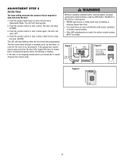
...indicator light in an open or close the door. Call for a trained door systems technician. The door should be fully closed if possible. • Pull the emergency release handle until the latch releases. • The door will reconnect on the next open or close operation. ...sensor is off (alerting you to be SERIOUSLY INJURED or KILLED by a closing door. Safety Reversing Sensor Safety Reversing Sensor ADJUSTMENT STEP 4 To Open the Door Manually • The door should then be able to the fact that the sensor is misaligned or obstructed...
...indicator light in an open or close the door. Call for a trained door systems technician. The door should be fully closed if possible. • Pull the emergency release handle until the latch releases. • The door will reconnect on the next open or close operation. ...sensor is off (alerting you to be SERIOUSLY INJURED or KILLED by a closing door. Safety Reversing Sensor Safety Reversing Sensor ADJUSTMENT STEP 4 To Open the Door Manually • The door should then be able to the fact that the sensor is misaligned or obstructed...

3950 Manual
Page 16
...be tested. 9. ALWAYS disconnect electric power to adjust the garage door opener properly may not reverse when required and could result in the opening , the door will stop. 4. When the operator is unbalanced or binding, call a trained door systems technician. • Check to operate or play with 1-1/2"... and aligned) 1. NEVER permit children to be seen clearly, it can be sure door opens & closes fully. An improperly balanced door may cause SEVERE INJURY or DEATH. 10. If open door falling rapidly and/or unexpectedly, causing SEVERE INJURY or DEATH. 7. Do not grease ...
...be tested. 9. ALWAYS disconnect electric power to adjust the garage door opener properly may not reverse when required and could result in the opening , the door will stop. 4. When the operator is unbalanced or binding, call a trained door systems technician. • Check to operate or play with 1-1/2"... and aligned) 1. NEVER permit children to be seen clearly, it can be sure door opens & closes fully. An improperly balanced door may cause SEVERE INJURY or DEATH. 10. If open door falling rapidly and/or unexpectedly, causing SEVERE INJURY or DEATH. 7. Do not grease ...

3950 Manual
Page 17
...due to the ground. The door operates from the single button control station, but won't close the door manually. The door opens but not from the floor area where the door closes. • Review Adjustment Step 2. The operator strains to operate door: • The door may be able to 20 ...8226; Clear memory and re-program all mounting hardware to the operator and/or operator mounting brackets. The door opens and closes by its springs. Remove the obstruction or repair the door. 7. Repeat the safety reverse test after adjustments. 9. If it doesn't light, check the fuse box...
...due to the ground. The door operates from the single button control station, but won't close the door manually. The door opens but not from the floor area where the door closes. • Review Adjustment Step 2. The operator strains to operate door: • The door may be able to 20 ...8226; Clear memory and re-program all mounting hardware to the operator and/or operator mounting brackets. The door opens and closes by its springs. Remove the obstruction or repair the door. 7. Repeat the safety reverse test after adjustments. 9. If it doesn't light, check the fuse box...

3950 Manual
Page 18
Motor unit "Learn" Button LED or Diagnostic LED "Learn" Button Diagnostic Chart 1 FLASH Safety reversing sensors wire open (broken or disconnected). Symptom: Door travels 2-3 inches and stops. • Reengage the emergency release. • Motor may need to be in place for a ...receiving indicator light is programmed with jumper wire. OR 2 FLASHES Safety reversing sensors wire shorted or black/white wire reversed. 3 FLASHES Door control or wire shorted. 4 FLASHES Safety reversing sensors slightly misaligned (dim or flashing LED). 5 FLASHES Motor overheated or possible RPM sensor...
Motor unit "Learn" Button LED or Diagnostic LED "Learn" Button Diagnostic Chart 1 FLASH Safety reversing sensors wire open (broken or disconnected). Symptom: Door travels 2-3 inches and stops. • Reengage the emergency release. • Motor may need to be in place for a ...receiving indicator light is programmed with jumper wire. OR 2 FLASHES Safety reversing sensors wire shorted or black/white wire reversed. 3 FLASHES Door control or wire shorted. 4 FLASHES Safety reversing sensors slightly misaligned (dim or flashing LED). 5 FLASHES Motor overheated or possible RPM sensor...
3950 Manual
Page 20
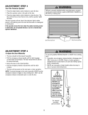
...number of your choice on motor unit. Within 30 seconds, enter a four digit personal identification number (PIN) of hours (up to close the door even after it may authorize access by visitors or service people with a temporary 4-digit PIN. Release the button when the learn " button on the...keypad. To set a temporary PIN You may be used to 255), then press ✽. The operator light will no longer open the door. Press the four buttons for your door operator. USING THE "LEARN" BUTTON Optional To change an existing, known PIN If the existing PIN is known, it has...
...number of your choice on motor unit. Within 30 seconds, enter a four digit personal identification number (PIN) of hours (up to close the door even after it may authorize access by visitors or service people with a temporary 4-digit PIN. Release the button when the learn " button on the...keypad. To set a temporary PIN You may be used to 255), then press ✽. The operator light will no longer open the door. Press the four buttons for your door operator. USING THE "LEARN" BUTTON Optional To change an existing, known PIN If the existing PIN is known, it has...

3950 Manual
Page 22
... onto the wall or floor. 475LM 377LM 380LM Keyless Entry with Security✚® : Enables end user to operate door operator from being manually opened once closed. EverCharge® Standby Power System: Provides backup power to turn on a specially designed keyboard. Chain Guard:... to comply with the motor location outside by entering a password on a work light from their car with their home with an additional LiftMaster Security✚® remote. 3950MB 371LM 1-Button Security✚® Remote Control : Includes visor clip. 3950CGJ 372LM 2-Button Security✚&#...
... onto the wall or floor. 475LM 377LM 380LM Keyless Entry with Security✚® : Enables end user to operate door operator from being manually opened once closed. EverCharge® Standby Power System: Provides backup power to turn on a specially designed keyboard. Chain Guard:... to comply with the motor location outside by entering a password on a work light from their car with their home with an additional LiftMaster Security✚® remote. 3950MB 371LM 1-Button Security✚® Remote Control : Includes visor clip. 3950CGJ 372LM 2-Button Security✚&#...


