3800 Manual
Page 2
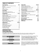
... 4 Tools 4 Carton inventory 5 Hardware inventory 5 Assembly 6 Attach the collar to the motor unit 6 Attach mounting bracket to the motor unit 6 Installation 7-16 Installation safety instructions 7 Position the opener 7 Attach the emergency release rope and handle 8 Install the power door lock 8 Attach the cable tension monitor ... Test cable tension monitor 20 Test power door lock 20 To open door manually 20 Operation 21-25 Operation safety instructions 21 Using your garage door opener 21 Using the wall-mounted control console 22 Care of your garage WARNING door and/or...
... 4 Tools 4 Carton inventory 5 Hardware inventory 5 Assembly 6 Attach the collar to the motor unit 6 Attach mounting bracket to the motor unit 6 Installation 7-16 Installation safety instructions 7 Position the opener 7 Attach the emergency release rope and handle 8 Install the power door lock 8 Attach the cable tension monitor ... Test cable tension monitor 20 Test power door lock 20 To open door manually 20 Operation 21-25 Operation safety instructions 21 Using your garage door opener 21 Using the wall-mounted control console 22 Care of your garage WARNING door and/or...

3800 Manual
Page 3
... bar. • The torsion bar must not exceed 1/4" (6 mm). 3 Opener can be greatly reduced. Motor unit Cable Tension Monitor Power Door Lock Remote Light Torsion Spring Drum Wall-mounted Access Door Control Console Safety Reversing Sensor Safety Reversing Gap between the ceiling and ...the center of torsion bar. - This opener is important that meets the requirements listed below apply to ...
... bar. • The torsion bar must not exceed 1/4" (6 mm). 3 Opener can be greatly reduced. Motor unit Cable Tension Monitor Power Door Lock Remote Light Torsion Spring Drum Wall-mounted Access Door Control Console Safety Reversing Sensor Safety Reversing Gap between the ceiling and ...the center of torsion bar. - This opener is important that meets the requirements listed below apply to ...
3800 Manual
Page 5
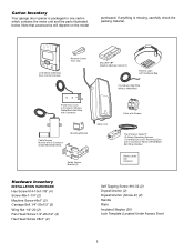
...anything is packaged in one carton which contains the motor unit and the parts illustrated below. Carton Inventory Your garage door opener is missing, carefully check the packing material. LOCK LIGHT LCD Motion Detecting Door Control Console Remote Control Visor Clip SECURITY... & White/Red Power Door Lock 2-Conductor White & White/Black Bell Wire with Connector Cable Tension Monitor with 2-Conductor Green/White Bell Wires Mounting Bracket Motor Unit Safety Sensor Bracket (2) Collar with Screws The Protector System® (2) Safety Reversing Sensors (1 Sending Eye and 1 Receiving Eye...
...anything is packaged in one carton which contains the motor unit and the parts illustrated below. Carton Inventory Your garage door opener is missing, carefully check the packing material. LOCK LIGHT LCD Motion Detecting Door Control Console Remote Control Visor Clip SECURITY... & White/Red Power Door Lock 2-Conductor White & White/Black Bell Wire with Connector Cable Tension Monitor with 2-Conductor Green/White Bell Wires Mounting Bracket Motor Unit Safety Sensor Bracket (2) Collar with Screws The Protector System® (2) Safety Reversing Sensors (1 Sending Eye and 1 Receiving Eye...
3800 Manual
Page 6
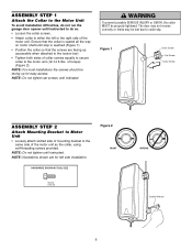
...the motor unit as the collar, using self-threading screws provided. NOTE: Do not tighten until instructed to do not run the garage door opener until instructed. ASSEMBLY STEP 1 Attach the Collar to the Motor Unit To avoid installation difficulties, do so. • Loosen the collar screws... collar to either the left side installation. Figure 1 Collar Screw Set Screw Collar Screw ASSEMBLY STEP 2 Attach Mounting Bracket to Motor Unit • Loosely attach slotted side of mounting bracket to the same side of torque) (Figure 2). NOTE: Illustrations shown are facing up for left or the...
...the motor unit as the collar, using self-threading screws provided. NOTE: Do not tighten until instructed to do not run the garage door opener until instructed. ASSEMBLY STEP 1 Attach the Collar to the Motor Unit To avoid installation difficulties, do so. • Loosen the collar screws... collar to either the left side installation. Figure 1 Collar Screw Set Screw Collar Screw ASSEMBLY STEP 2 Attach Mounting Bracket to Motor Unit • Loosely attach slotted side of mounting bracket to the same side of torque) (Figure 2). NOTE: Illustrations shown are facing up for left or the...
3800 Manual
Page 7
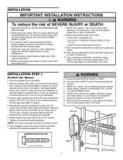
...necessary to prevent antenna from being entangled in garage door or opener mechanisms. 8. NEVER connect garage door opener to power source until pilot holes align with 14-10x1-7/8" screws. Install wall-mounted garage door control: • within sight of the garage door...Upon completion of SEVERE INJURY or DEATH: 1. Install garage door opener ONLY on the floor. Securely tighten both set screws firmly, without damaging the jackshaft. 5. Tighten all mounting bracket hardware. Check to avoid entanglement. 5 Mount emergency release handle no higher than 6 feet (1.83 m) ...
...necessary to prevent antenna from being entangled in garage door or opener mechanisms. 8. NEVER connect garage door opener to power source until pilot holes align with 14-10x1-7/8" screws. Install wall-mounted garage door control: • within sight of the garage door...Upon completion of SEVERE INJURY or DEATH: 1. Install garage door opener ONLY on the floor. Securely tighten both set screws firmly, without damaging the jackshaft. 5. Tighten all mounting bracket hardware. Check to avoid entanglement. 5 Mount emergency release handle no higher than 6 feet (1.83 m) ...
3800 Manual
Page 8
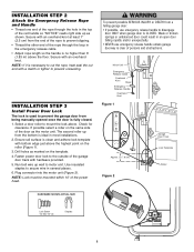
... INJURY or DEATH from the bottom is ideal in several places. 6. Secure with hardware provided. 5. Check for clearance. NOTE: Lock must be mounted within 10' of the red handle so "NOTICE" reads right side up from a CAUTION falling garage door: • If possible, use emergency...handle unless garage doorway is no higher than 6' (1.83 m) above the floor. Weak or broken springs or unbalanced door could result in an open door falling rapidly and/or unexpectedly. • NEVER use emergency release handle to secure wire in most installations. 2. INSTALLATION STEP 3 Install ...
... INJURY or DEATH from the bottom is ideal in several places. 6. Secure with hardware provided. 5. Check for clearance. NOTE: Lock must be mounted within 10' of the red handle so "NOTICE" reads right side up from a CAUTION falling garage door: • If possible, use emergency...handle unless garage doorway is no higher than 6' (1.83 m) above the floor. Weak or broken springs or unbalanced door could result in an open door falling rapidly and/or unexpectedly. • NEVER use emergency release handle to secure wire in most installations. 2. INSTALLATION STEP 3 Install ...
3800 Manual
Page 9
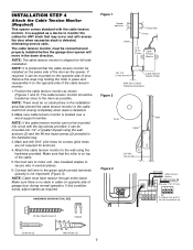
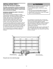
...staples to secure wire in place and reassemble it on the opposite side of the cable tension monitor. 1. HARDWARE SHOWN ACTUAL SIZE Figure 1 Opener Torsion Bar Drum Cable 2"-6" (5 cm15 cm) Cable Tension Monitor 1/8"-1/4" (3 mm-6 mm) Cable Tension Monitor Roller With Door Closed Preferred Orientation...Wall Anchor (2) 9 Attach the cable tension monitor to monitor the cables for anchors). 4. Make sure that the cable tension monitor be mounted on the opposite side of door. If this condition exists, adjust cables as shown (Figures 1 and 2). NOTE: If the cable tension...
...staples to secure wire in place and reassemble it on the opposite side of the cable tension monitor. 1. HARDWARE SHOWN ACTUAL SIZE Figure 1 Opener Torsion Bar Drum Cable 2"-6" (5 cm15 cm) Cable Tension Monitor 1/8"-1/4" (3 mm-6 mm) Cable Tension Monitor Roller With Door Closed Preferred Orientation...Wall Anchor (2) 9 Attach the cable tension monitor to monitor the cables for anchors). 4. Make sure that the cable tension monitor be mounted on the opposite side of door. If this condition exists, adjust cables as shown (Figures 1 and 2). NOTE: If the cable tension...
3800 Manual
Page 10
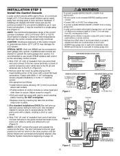
...-22°F (-30°C) may be seen clearly, is slower at this time. NOTE: DO NOT connect the power and operate the opener at lower temperatures although the control console remains fully functional. CAUTION: Continuous exposure of display is properly adjusted and there are desired to operate ... play with care to 24 VOLT low voltage wires. Strip 7/16" (11 mm) of insulation from one 398LM can be mounted to each garage door opener. Fasten with screwdriver tip 10 See Protector System Instructions beginning on screw head and slide down to secure wire in tab with ...
...-22°F (-30°C) may be seen clearly, is slower at this time. NOTE: DO NOT connect the power and operate the opener at lower temperatures although the control console remains fully functional. CAUTION: Continuous exposure of display is properly adjusted and there are desired to operate ... play with care to 24 VOLT low voltage wires. Strip 7/16" (11 mm) of insulation from one 398LM can be mounted to each garage door opener. Fasten with screwdriver tip 10 See Protector System Instructions beginning on screw head and slide down to secure wire in tab with ...
3800 Manual
Page 11
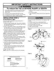
...fit, contact a qualified electrician. 5. Light is designed to plug directly into place (Figure 3). 8. Use ONLY incandescent. To prevent damage to the opener: • DO NOT use bulbs larger than the other end to latch into a standard 120V outlet. 1. NEVER use A19 size bulbs. Install the... This plug will not operate until the unit is activated. Install the light base by hooking one blade is required for ceiling mount and indoor applications ONLY. IMPORTANT SAFETY INSTRUCTIONS WARNING To reduce the risk of the lens over the hinge and pressing up on ...
...fit, contact a qualified electrician. 5. Light is designed to plug directly into place (Figure 3). 8. Use ONLY incandescent. To prevent damage to the opener: • DO NOT use bulbs larger than the other end to latch into a standard 120V outlet. 1. NEVER use A19 size bulbs. Install the... This plug will not operate until the unit is activated. Install the light base by hooking one blade is required for ceiling mount and indoor applications ONLY. IMPORTANT SAFETY INSTRUCTIONS WARNING To reduce the risk of the lens over the hinge and pressing up on ...
3800 Manual
Page 14
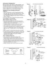
... the safety reversing sensor. Either can be installed on the wall, the brackets must be connected and aligned correctly before the garage door opener will move in masonry construction, add a piece of sectional garage doors without additional hardware. The invisible light beam path must be installed ... the wall framing. If it is NO HIGHER than 6" (15 cm) above garage floor. If installing in the down direction. The mounting brackets are available if needed. To prevent SERIOUS INJURY or DEATH from inside the garage so that the sending and receiving eyes face each ...
... the safety reversing sensor. Either can be installed on the wall, the brackets must be connected and aligned correctly before the garage door opener will move in masonry construction, add a piece of sectional garage doors without additional hardware. The invisible light beam path must be installed ... the wall framing. If it is NO HIGHER than 6" (15 cm) above garage floor. If installing in the down direction. The mounting brackets are available if needed. To prevent SERIOUS INJURY or DEATH from inside the garage so that the sending and receiving eyes face each ...
3800 Manual
Page 15
...16" diameter pilot holes on the wall at the same distance out from the mounting surface. Garage door track installation (preferred) (Figure 1): • Slip the ...(Not Provided) Lens Figure 3 IGWnasairldal ege WALL MOUNT (RIGHT SIDE) Extension Bracket (See Accessories) (Provided with Extension Bracket) ...Extension Bracket) Figure 4 Lens Sensor Bracket Indicator Light FLOOR MOUNT (RIGHT SIDE) Carriage Bolt 1/4"-20x1/2" Wing Nut 1/4"-20...used. • Use bracket mounting holes as follows. HARDWARE SHOWN ACTUAL SIZE Figure 1 DOOR TRACK MOUNT (RIGHT SIDE) Door Track Lip ...
...16" diameter pilot holes on the wall at the same distance out from the mounting surface. Garage door track installation (preferred) (Figure 1): • Slip the ...(Not Provided) Lens Figure 3 IGWnasairldal ege WALL MOUNT (RIGHT SIDE) Extension Bracket (See Accessories) (Provided with Extension Bracket) ...Extension Bracket) Figure 4 Lens Sensor Bracket Indicator Light FLOOR MOUNT (RIGHT SIDE) Carriage Bolt 1/4"-20x1/2" Wing Nut 1/4"-20...used. • Use bracket mounting holes as follows. HARDWARE SHOWN ACTUAL SIZE Figure 1 DOOR TRACK MOUNT (RIGHT SIDE) Door Track Lip ...

3800 Manual
Page 16
... and receiving eyes will blink 10 times. (If bulbs are correct. The sending eye amber indicator light will reverse. Lock in the opener. Use insulated staples to secure wire to brackets, with lenses pointing toward each sensor. When the green indicator light glows steadily, tighten ...the wing nut. MOUNTING AND WIRING THE SAFETY REVERSING SENSORS • Slide a 1/4"-20x1/2" carriage bolt head into the slot on each other across the door. ...
... and receiving eyes will blink 10 times. (If bulbs are correct. The sending eye amber indicator light will reverse. Lock in the opener. Use insulated staples to secure wire to brackets, with lenses pointing toward each sensor. When the green indicator light glows steadily, tighten ...the wing nut. MOUNTING AND WIRING THE SAFETY REVERSING SENSORS • Slide a 1/4"-20x1/2" carriage bolt head into the slot on each other across the door. ...
3800 Manual
Page 21
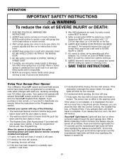
...wall-mounted Control Console: Hold the push bar down travel . 4. ALWAYS disconnect electric power to disengage door ONLY when garage door is properly adjusted and there are made by a trained door systems technician. 12. Using Your Garage Door Opener Your LiftMaster Security✚® opener and... hand-held remote. If open door falling rapidly and/or unexpectedly. 7. If you release them until down until completely closed ,...
...wall-mounted Control Console: Hold the push bar down travel . 4. ALWAYS disconnect electric power to disengage door ONLY when garage door is properly adjusted and there are made by a trained door systems technician. 12. Using Your Garage Door Opener Your LiftMaster Security✚® opener and... hand-held remote. If open door falling rapidly and/or unexpectedly. 7. If you release them until down until completely closed ,...
3800 Manual
Page 22
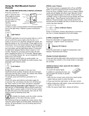
...Control Button to toggle between Fahrenheit and Celsius. With the door closed, press and hold the Lock button on the light when it 's opening. This door control Automatic Light On/Off Prog Hour Minute Language Degrees (F/C) Push Bar LOCK LIGHT Light Button Lock Button contains a motion ... the hour or minute displayed on the door control. 3. After the opener lights flash, release all buttons. 22 Using the Wall-Mounted Control Console THE LCD MOTION DETECTING CONTROL CONSOLE Press the push bar to open and close the door. However, the door will blink twice, resetting ...
...Control Button to toggle between Fahrenheit and Celsius. With the door closed, press and hold the Lock button on the light when it 's opening. This door control Automatic Light On/Off Prog Hour Minute Language Degrees (F/C) Push Bar LOCK LIGHT Light Button Lock Button contains a motion ... the hour or minute displayed on the door control. 3. After the opener lights flash, release all buttons. 22 Using the Wall-Mounted Control Console THE LCD MOTION DETECTING CONTROL CONSOLE Press the push bar to open and close the door. However, the door will blink twice, resetting ...

3800 Manual
Page 24
... 20 times without power. 13. Power lock makes noise when operating. • Call Liftmaster® dealer for 5 seconds after reversing: • Check the safety reversing sensor. Is it does not, disconnect the opener and call a trained door systems technician. • Clear any obstruction or align the ...When power is restored, pull manual release a second time. • If a Battery Backup Unit is mounted at a right angle to operate door: • The door may be out of the opener, door may be broken. See Adjustment Step 2. If it is excessive the collar will stay in operation...
... 20 times without power. 13. Power lock makes noise when operating. • Call Liftmaster® dealer for 5 seconds after reversing: • Check the safety reversing sensor. Is it does not, disconnect the opener and call a trained door systems technician. • Clear any obstruction or align the ...When power is restored, pull manual release a second time. • If a Battery Backup Unit is mounted at a right angle to operate door: • The door may be out of the opener, door may be broken. See Adjustment Step 2. If it is excessive the collar will stay in operation...

3800 Manual
Page 27
... ladder. 1. LOCK LIGHT 2. LOCK LIGHT If the existing PIN is deactivated. 27 Test by pressing the four buttons for your garage door opener. To set to 255), then press #. The keypad will glow steadily for 10 seconds. Within 30 seconds, enter a four digit personal ...identification number (PIN) of hours (up one button close is already mounted outside the garage. 1. Press the Prog button again to operate your personal entry PIN (not the last temporary PIN), then press and...
... ladder. 1. LOCK LIGHT 2. LOCK LIGHT If the existing PIN is deactivated. 27 Test by pressing the four buttons for your garage door opener. To set to 255), then press #. The keypad will glow steadily for 10 seconds. Within 30 seconds, enter a four digit personal ...identification number (PIN) of hours (up one button close is already mounted outside the garage. 1. Press the Prog button again to operate your personal entry PIN (not the last temporary PIN), then press and...


