3585 Elite Series Manual
Page 2
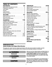
... . . .33 To erase all codes from electric shock. Read the warnings carefully. The hazard may come from something mechanical or from motor unit memory 33 3-Button remotes 33 To add, reprogram or change a Keyless Entry PIN . . . .34 Repair Parts 35-36 ...word review 2 Preparing your garage door 3 Tools needed 3 Planning 4 Carton inventory 5 Hardware inventory 5 Assembly 6-7 Attach the rail to the motor unit 6 Set the belt tension 6 Attach the belt cap retainer 7 Installation 7-22 Installation safety instructions 7 Determine the header bracket location 8 Install...
... . . .33 To erase all codes from electric shock. Read the warnings carefully. The hazard may come from something mechanical or from motor unit memory 33 3-Button remotes 33 To add, reprogram or change a Keyless Entry PIN . . . .34 Repair Parts 35-36 ...word review 2 Preparing your garage door 3 Tools needed 3 Planning 4 Carton inventory 5 Hardware inventory 5 Assembly 6-7 Attach the rail to the motor unit 6 Set the belt tension 6 Attach the belt cap retainer 7 Installation 7-22 Installation safety instructions 7 Determine the header bracket location 8 Install...
3585 Elite Series Manual
Page 4
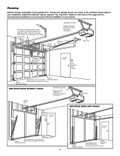
... page 19 for lightweight garage doors (fiberglass, steel, aluminum, door with the installation of your opener. See page 12. Torsion Spring Extension Spring OR Motor Unit --- --- -- Motor Unit Header Wall Wallmounted Door Control Access Door ONE-PIECE DOOR WITH TRACK Safety Reversing Sensor Gap between floor and bottom of Safety door must...
... page 19 for lightweight garage doors (fiberglass, steel, aluminum, door with the installation of your opener. See page 12. Torsion Spring Extension Spring OR Motor Unit --- --- -- Motor Unit Header Wall Wallmounted Door Control Access Door ONE-PIECE DOOR WITH TRACK Safety Reversing Sensor Gap between floor and bottom of Safety door must...
3585 Elite Series Manual
Page 5
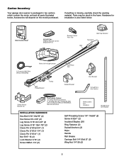
...carefully check the packing material. Accessories will depend on the model purchased. Parts may be stuck in two cartons which contain the motor unit and all parts illustrated below . Carton Inventory Your garage door opener is packaged in the foam. LOCK LIGHT SmLCarDt CMoontitoronl...Button Remote Control Model 373P (1) Remote Control TVrisaonrsmCliitpter Visor Clip Belt Belt Cap Retainer Styrofoam 2-Conductor Bell Wire White & White/Red Motor Unit w/Light Lenses Belt Pulley Bracket Trolley One-Piece Rail CEILING MOUNT ONLY UP Header Bracket Door Bracket Curved Door Arm Section ...
...carefully check the packing material. Accessories will depend on the model purchased. Parts may be stuck in two cartons which contain the motor unit and all parts illustrated below . Carton Inventory Your garage door opener is packaged in the foam. LOCK LIGHT SmLCarDt CMoontitoronl...Button Remote Control Model 373P (1) Remote Control TVrisaonrsmCliitpter Visor Clip Belt Belt Cap Retainer Styrofoam 2-Conductor Bell Wire White & White/Red Motor Unit w/Light Lenses Belt Pulley Bracket Trolley One-Piece Rail CEILING MOUNT ONLY UP Header Bracket Door Bracket Curved Door Arm Section ...
3585 Elite Series Manual
Page 6
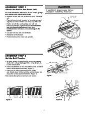
... trolley (Figure 2). • Place a 7/16" open end wrench on the motor unit and align the back hole with the washered bolt and lock nut previously removed. Liftmaster Synchro Drive • Cut tape from the top of the motor unit. • Place rail onto the bolt mounted on the square end. Do... not use any tools. • Insert a screwdriver tip into one of the unit. • Fasten rail with the hole in top of motor unit. ...
... trolley (Figure 2). • Place a 7/16" open end wrench on the motor unit and align the back hole with the washered bolt and lock nut previously removed. Liftmaster Synchro Drive • Cut tape from the top of the motor unit. • Place rail onto the bolt mounted on the square end. Do... not use any tools. • Insert a screwdriver tip into one of the unit. • Fasten rail with the hole in top of motor unit. ...
3585 Elite Series Manual
Page 7
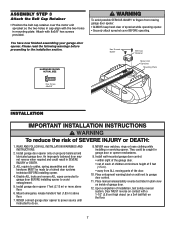
...INSTRUCTIONS. installing or servicing opener. Mount emergency release handle 6 feet (1.83 m) above floor. 6. Hex Screws 8x3/8" Belt Cap Retainer Motor Unit Sprocket Mounting Plate Hex Screw #8x3/8" INSTALLATION WARNING IMPORTANT INSTALLATION INSTRUCTIONS WARNING To reduce the risk of installation, test safety reversal ...opener mechanisms. lubricated garage door. ASSEMBLY STEP 3 Attach the Belt Cap Retainer • Position the belt cap retainer over the motor unit sprocket so the two holes in cap align with 8x3/8" hex screws provided. Attach with the two holes in 2. ...
...INSTRUCTIONS. installing or servicing opener. Mount emergency release handle 6 feet (1.83 m) above floor. 6. Hex Screws 8x3/8" Belt Cap Retainer Motor Unit Sprocket Mounting Plate Hex Screw #8x3/8" INSTALLATION WARNING IMPORTANT INSTALLATION INSTRUCTIONS WARNING To reduce the risk of installation, test safety reversal ...opener mechanisms. lubricated garage door. ASSEMBLY STEP 3 Attach the Belt Cap Retainer • Position the belt cap retainer over the motor unit sprocket so the two holes in cap align with 8x3/8" hex screws provided. Attach with the two holes in 2. ...
3585 Elite Series Manual
Page 11
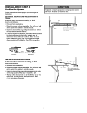
Slide the outer trolley toward the motor unit. The trolley can remain disconnected until Installation Step 12 is used to your door type as illustrated. ENGAGED Trolley Release Arm RELEASED ONE-PIECE ... top section of the door beneath the rail. • The top of the door should be level with the top of the motor unit. Header Bracket Top of Motor Unit Top of door. Rail Door 2x4 is convenient for setting an ideal door-to disconnect inner and outer sections. INSTALLATION STEP 4 Position...
Slide the outer trolley toward the motor unit. The trolley can remain disconnected until Installation Step 12 is used to your door type as illustrated. ENGAGED Trolley Release Arm RELEASED ONE-PIECE ... top section of the door beneath the rail. • The top of the door should be level with the top of the motor unit. Header Bracket Top of Motor Unit Top of door. Rail Door 2x4 is convenient for setting an ideal door-to disconnect inner and outer sections. INSTALLATION STEP 4 Position...
3585 Elite Series Manual
Page 12
... anchors MUST be used if installing any brackets into masonry. On finished ceilings (Figure 2 and Figure 3), attach a sturdy metal bracket to structural supports of the motor unit to the hanging brackets with 5/16"-18x1-7/8" lag screws. 5. Attach one end of each side of the garage.
... anchors MUST be used if installing any brackets into masonry. On finished ceilings (Figure 2 and Figure 3), attach a sturdy metal bracket to structural supports of the motor unit to the hanging brackets with 5/16"-18x1-7/8" lag screws. 5. Attach one end of each side of the garage.
3585 Elite Series Manual
Page 13
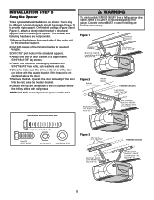
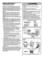
... installations (as follows: • Install bottom screw, allowing 1/8" (3 mm) to protrude above wall surface. • Position bottom of door control on the motor unit: white to white and white/red to secure wire in new home construction), it can be mounted to the R (1) (Figure 2). 2. Fasten with 6AB...mm) of insulation from electrocution: • Be sure power is recommended to temperatures below -22° F (-30° C) may be connected to motor unit. To release or insert wire, push in tab with care to 24 VOLT low voltage wires. DO NOT connect power and operate the opener...
... installations (as follows: • Install bottom screw, allowing 1/8" (3 mm) to protrude above wall surface. • Position bottom of door control on the motor unit: white to white and white/red to secure wire in new home construction), it can be mounted to the R (1) (Figure 2). 2. Fasten with 6AB...mm) of insulation from electrocution: • Be sure power is recommended to temperatures below -22° F (-30° C) may be connected to motor unit. To release or insert wire, push in tab with care to 24 VOLT low voltage wires. DO NOT connect power and operate the opener...

3585 Elite Series Manual
Page 15
... connected to the opener, and disconnect power to circuit BEFORE removing cover to install the proper outlet. To reduce the risk of the motor unit: • Remove the motor unit cover screws and set the cover aside. • Remove the attached 3-prong cord. • Connect the black (line) wire to make a permanent...
... connected to the opener, and disconnect power to circuit BEFORE removing cover to install the proper outlet. To reduce the risk of the motor unit: • Remove the motor unit cover screws and set the cover aside. • Remove the attached 3-prong cord. • Connect the black (line) wire to make a permanent...

3585 Elite Series Manual
Page 23
... clockwise. Door MUST reverse on floor. Test the door for a trained door systems technician. If the door is adjusted, the other control may cause the motor to Adjustment Step 2. ADJUSTMENT STEP 1 Adjust the UP and DOWN Travel Limits Limit adjustment settings regulate the points at least 5 feet (1.5 m): Increase up or down...
... clockwise. Door MUST reverse on floor. Test the door for a trained door systems technician. If the door is adjusted, the other control may cause the motor to Adjustment Step 2. ADJUSTMENT STEP 1 Adjust the UP and DOWN Travel Limits Limit adjustment settings regulate the points at least 5 feet (1.5 m): Increase up or down...

3585 Elite Series Manual
Page 24
... and the opener lights aren't flashing, INCREASE DOWN (close cycle. Make small adjustments until door opens completely. Force adjustment settings regulate the amount of the motor unit. Turn force adjustment controls with 1-1/2" high (3.8 cm) object (or 2x4 laid flat) on the back panel of power required to hold or doesn't stop...
... and the opener lights aren't flashing, INCREASE DOWN (close cycle. Make small adjustments until door opens completely. Force adjustment settings regulate the amount of the motor unit. Turn force adjustment controls with 1-1/2" high (3.8 cm) object (or 2x4 laid flat) on the back panel of power required to hold or doesn't stop...

3585 Elite Series Manual
Page 27
... (Automatic Light Feature): The opener light will blink twice, resetting the timer to 1-1/2 minutes. To disable this feature, push the motion sensing button on the motor unit panel is reset to 2-1/2 minutes. However, the door will also turn on LIGHT or off whenever the "learn" button on the side of four...
... (Automatic Light Feature): The opener light will blink twice, resetting the timer to 1-1/2 minutes. To disable this feature, push the motion sensing button on the motor unit panel is reset to 2-1/2 minutes. However, the door will also turn on LIGHT or off whenever the "learn" button on the side of four...

3585 Elite Series Manual
Page 30
...The need for occasional adjustment for the force and limit settings is blinking, deactivate the Lock Mode following the instructions for flashes on the motor unit then refer to disengage. • Decrease the UP travel towards the door and stop bolt. • Release the door from the... Eye Safety Reversing Sensor (Green Indicator Light) 3. Weather conditions in particular can affect door travel . • Manually check door for flashes on motor unit then refer to 5 turns. My door reverses for the force and limit settings is approximately 1-1/4" (3.18 cm) in length. • If...
...The need for occasional adjustment for the force and limit settings is blinking, deactivate the Lock Mode following the instructions for flashes on the motor unit then refer to disengage. • Decrease the UP travel towards the door and stop bolt. • Release the door from the... Eye Safety Reversing Sensor (Green Indicator Light) 3. Weather conditions in particular can affect door travel . • Manually check door for flashes on motor unit then refer to 5 turns. My door reverses for the force and limit settings is approximately 1-1/4" (3.18 cm) in length. • If...

3585 Elite Series Manual
Page 31
... wires at door control, touch wires together. Symptom: LED is firmly secured to 1-2 ft. (30-60 cm) from motor unit. Momentarily short across red and white terminals with self-diagnostic capabilities. Symptom: Sending indicator light glows steadily, receiving indicator light... Safety reversing sensors wire open (broken or disconnected). Bell Wire Diagnostics Located On 9 1 9 1 7 3 7 3 5 5 KG KG Motor Unit Safety Reversing Sensor "Learn" Button LED or Diagnostic LED Diagnostic Chart Installed Safety Reversing Sensor Your garage door opener is stuck on stop bolt...
... wires at door control, touch wires together. Symptom: LED is firmly secured to 1-2 ft. (30-60 cm) from motor unit. Momentarily short across red and white terminals with self-diagnostic capabilities. Symptom: Sending indicator light glows steadily, receiving indicator light... Safety reversing sensors wire open (broken or disconnected). Bell Wire Diagnostics Located On 9 1 9 1 7 3 7 3 5 5 KG KG Motor Unit Safety Reversing Sensor "Learn" Button LED or Diagnostic LED Diagnostic Chart Installed Safety Reversing Sensor Your garage door opener is stuck on stop bolt...
3585 Elite Series Manual
Page 32
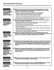
...has been pressed on the opener. Meaning: This message will appear if the Safety Reversing Sensors are blocked or if the wiring is ready to motor unit using shortened wires. Message ENGLISH, FRANÇAIS AND ESPAÑOL. Meaning: This message will appear when the 'MOTION SENSING' ...held for a short (staple in wire), correct wiring polarity (black/white wires reversed), replace/attach as needed. • Disconnect all wires from back of motor unit. • Remove safety sensors from brackets and shorten sensor wires to 1-2 ft. (30-60 cm) from back of each press of the unit...
...has been pressed on the opener. Meaning: This message will appear if the Safety Reversing Sensors are blocked or if the wiring is ready to motor unit using shortened wires. Message ENGLISH, FRANÇAIS AND ESPAÑOL. Meaning: This message will appear when the 'MOTION SENSING' ...held for a short (staple in wire), correct wiring polarity (black/white wires reversed), replace/attach as needed. • Disconnect all wires from back of motor unit. • Remove safety sensors from brackets and shorten sensor wires to 1-2 ft. (30-60 cm) from back of each press of the unit...

3585 Elite Series Manual
Page 33
...of the non-rolling code transmitter to circumvent that technical measure. The learn indicator light will be circumvented. Release the button when the motor unit lights blink. Below are not installed, two clicks will glow steadily for programming your garage door. 4. Within 30 seconds, press ...and hold the "learn" button on motor unit until the learn " button on the hand-held remote that you wish to operate your opener to operate with additional Security✚&#...
...of the non-rolling code transmitter to circumvent that technical measure. The learn indicator light will be circumvented. Release the button when the motor unit lights blink. Below are not installed, two clicks will glow steadily for programming your garage door. 4. Within 30 seconds, press ...and hold the "learn" button on motor unit until the learn " button on the hand-held remote that you wish to operate your opener to operate with additional Security✚&#...

3585 Elite Series Manual
Page 34
... seconds. Press and release the "learn indicator light will blink twice when the one button close is deactivated. 34 Release the button when the motor unit lights blink. After a programmed number of hours or number of hours or times to 255), then press #. To set a temporary PIN..., repeat steps 1-3, setting the number of accesses, this temporary PIN will blink four times when one person without using a ladder. 1. When the motor unit lights blink, it may authorize access by pressing the four buttons for the present PIN, then press and hold buttons 1 and 9 for 30...
... seconds. Press and release the "learn indicator light will blink twice when the one button close is deactivated. 34 Release the button when the motor unit lights blink. After a programmed number of hours or number of hours or times to 255), then press #. To set a temporary PIN..., repeat steps 1-3, setting the number of accesses, this temporary PIN will blink four times when one person without using a ladder. 1. When the motor unit lights blink, it may authorize access by pressing the four buttons for the present PIN, then press and hold buttons 1 and 9 for 30...

3585 Elite Series Manual
Page 36
...grease 16 Drive/worm gear kit w/grease, 17 roll pins (2) 41A2822-1 41C4398A 41AB075-2 Line cord End panels w/all labels NOT SHOWN Motor shaft bearing kit Opener assembly hardware kit (includes screws not designated by a number in illustration) bracket, gear case, bearing assembly, RPM ... Complete with : Logic board, end panel w/all labels, light socket High voltage wire harness assy. NO. Complete with : Motor, worm, Interrupter cup assembly RPM sensor assembly Receiver logic board assy. Motor Unit Assembly Parts 7 6 4 18 17 1 2 3 6 5 7 19 8A 15 9 8B 16 8C 14 10...
...grease 16 Drive/worm gear kit w/grease, 17 roll pins (2) 41A2822-1 41C4398A 41AB075-2 Line cord End panels w/all labels NOT SHOWN Motor shaft bearing kit Opener assembly hardware kit (includes screws not designated by a number in illustration) bracket, gear case, bearing assembly, RPM ... Complete with : Logic board, end panel w/all labels, light socket High voltage wire harness assy. NO. Complete with : Motor, worm, Interrupter cup assembly RPM sensor assembly Receiver logic board assy. Motor Unit Assembly Parts 7 6 4 18 17 1 2 3 6 5 7 19 8A 15 9 8B 16 8C 14 10...

3585 Elite Series Manual
Page 40
...Pages, or call . Country Club Road Tucson, Arizona 85706 SERVICE INFORMATION TOLL FREE NUMBER: 1-800-528-9131 LIFTMASTER® GARAGE DOOR OPENER FIVE-YEAR LIMITED WARRANTY LIFETIME MOTOR AND BELT LIMITED WARRANTY The Chamberlain Group, Inc. ("Seller") warrants to our service center for warranty repair,... limitation may not apply to Seller for warranty repair. The proper operation of dealers in your local LIFTMASTER/CHAMBERLAIN dealer. Look for a period of five years from the date of purchase [and that the motor and belt are confirmed to you will be billed accordingly.
...Pages, or call . Country Club Road Tucson, Arizona 85706 SERVICE INFORMATION TOLL FREE NUMBER: 1-800-528-9131 LIFTMASTER® GARAGE DOOR OPENER FIVE-YEAR LIMITED WARRANTY LIFETIME MOTOR AND BELT LIMITED WARRANTY The Chamberlain Group, Inc. ("Seller") warrants to our service center for warranty repair,... limitation may not apply to Seller for warranty repair. The proper operation of dealers in your local LIFTMASTER/CHAMBERLAIN dealer. Look for a period of five years from the date of purchase [and that the motor and belt are confirmed to you will be billed accordingly.


