3255 Manual
Page 2
...word review 2 Preparing your garage door 3 Tools needed 3 Planning 4 Carton inventory 5 Hardware inventory 5 Assembly 6-7 Attach the rail to the motor unit 6 Attach the chain to the sprocket 6 Tighten the chain 7 Installation 7-22 Installation safety instructions 7 Determine the header bracket location 8 Install ... reprogram or change a Keyless Entry PIN 32 Repair Parts 33-34 Rail assembly parts 33 Installation parts 33 Motor unit assembly parts 34 Accessories 35 Repair Parts and Service 36 Warranty 36 INTRODUCTION Safety Symbol and Signal Word Review ...
...word review 2 Preparing your garage door 3 Tools needed 3 Planning 4 Carton inventory 5 Hardware inventory 5 Assembly 6-7 Attach the rail to the motor unit 6 Attach the chain to the sprocket 6 Tighten the chain 7 Installation 7-22 Installation safety instructions 7 Determine the header bracket location 8 Install ... reprogram or change a Keyless Entry PIN 32 Repair Parts 33-34 Rail assembly parts 33 Installation parts 33 Motor unit assembly parts 34 Accessories 35 Repair Parts and Service 36 Warranty 36 INTRODUCTION Safety Symbol and Signal Word Review ...
3255 Manual
Page 4
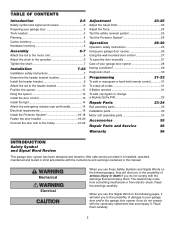
... details. FINISHED CEILING Support bracket & fastening hardware is closed . SECTIONAL DOOR INSTALLATION Horizontal and vertical reinforcement is closed . Motor Unit Wallmounted Door Control Access Door ONE-PIECE DOOR WITH TRACK Slack in chain tension is normal when garage door is required. ... between floor and bottom of Safety door must not exceed 1/4" (6 mm). Planning Identify the type and height of your installation. Motor Unit Vertical Centerline of door must not exceed 1/4" (6 mm). Access Door Safety Reversing Sensor Gap between floor Reversing Sensor and bottom of...
... details. FINISHED CEILING Support bracket & fastening hardware is closed . SECTIONAL DOOR INSTALLATION Horizontal and vertical reinforcement is closed . Motor Unit Wallmounted Door Control Access Door ONE-PIECE DOOR WITH TRACK Slack in chain tension is normal when garage door is required. ... between floor and bottom of Safety door must not exceed 1/4" (6 mm). Planning Identify the type and height of your installation. Motor Unit Vertical Centerline of door must not exceed 1/4" (6 mm). Access Door Safety Reversing Sensor Gap between floor Reversing Sensor and bottom of...
3255 Manual
Page 5
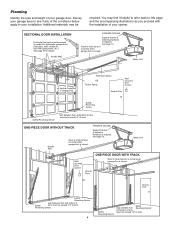
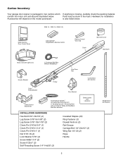
is missing, carefully check the packing material. contain the motor unit and all parts illustrated below . 3245 (1), 3255 (1), 3255-2 (2) LOCK LIGHT Multi-Function Door Control Panel : SECURITY ® Single-Button Remote Control Remote Control Visor Clip Chain Sprocket Cover Styrofoam Motor Unit with 2-Conductor White & White/Black Bell Wire attached Safety Labels and Literature INSTALLATION HARDWARE...
is missing, carefully check the packing material. contain the motor unit and all parts illustrated below . 3245 (1), 3255 (1), 3255-2 (2) LOCK LIGHT Multi-Function Door Control Panel : SECURITY ® Single-Button Remote Control Remote Control Visor Clip Chain Sprocket Cover Styrofoam Motor Unit with 2-Conductor White & White/Black Bell Wire attached Safety Labels and Literature INSTALLATION HARDWARE...
3255 Manual
Page 6
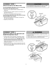
...USE ONLY THIS TYPE AND SIZE BOLT Sprocket Cover Back Tab Slot Front Tab Slot Mounting Plate 6 ASSEMBLY STEP 1 Attach the Rail to the Motor Unit To avoid installation difficulties, do not run the garage door opener until instructed to do so. • Remove the two washered bolts mounted in ...to garage door opener, use ONLY those bolts/fasteners mounted in . CAUTION: Use only the bolt previously removed from motor unit! • Tighten both bolts securely through the rail into the motor unit as shown. • Install the sprocket cover: Insert the back tab in the slot on the trolley to ...
...USE ONLY THIS TYPE AND SIZE BOLT Sprocket Cover Back Tab Slot Front Tab Slot Mounting Plate 6 ASSEMBLY STEP 1 Attach the Rail to the Motor Unit To avoid installation difficulties, do not run the garage door opener until instructed to do so. • Remove the two washered bolts mounted in ...to garage door opener, use ONLY those bolts/fasteners mounted in . CAUTION: Use only the bolt previously removed from motor unit! • Tighten both bolts securely through the rail into the motor unit as shown. • Install the sprocket cover: Insert the back tab in the slot on the trolley to ...
3255 Manual
Page 11
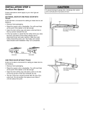
Slide the outer trolley toward the motor unit. To prevent damage to your door type as illustrated. ENGAGED Trolley Release Arm RELEASED ONE-PIECE DOOR WITHOUT TRACK A 2x4 on its side on the ... place a 2x4 on the trolley release arm to -rail distance. • Remove foam packaging. • Raise the opener onto a stepladder. Header Bracket Top of the motor unit. Rail Door 2x4 is used to determine the correct mounting height from ceiling. SECTIONAL DOOR OR ONE-PIECE DOOR WITH TRACK A 2x4 laid flat is...
Slide the outer trolley toward the motor unit. To prevent damage to your door type as illustrated. ENGAGED Trolley Release Arm RELEASED ONE-PIECE DOOR WITHOUT TRACK A 2x4 on its side on the ... place a 2x4 on the trolley release arm to -rail distance. • Remove foam packaging. • Raise the opener onto a stepladder. Header Bracket Top of the motor unit. Rail Door 2x4 is used to determine the correct mounting height from ceiling. SECTIONAL DOOR OR ONE-PIECE DOOR WITH TRACK A 2x4 laid flat is...
3255 Manual
Page 12
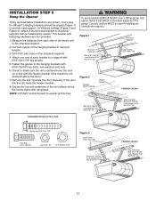
... 5/16"-18x7/8" Lock Washer 5/16" Nut 5/16"-18 12 Measure the distance from a falling garage door opener, fasten it SECURELY to structural supports of the motor unit to make sure the rail is centered over the door (or in the structural supports. 4. Grease the top and underside of each side of the...
... 5/16"-18x7/8" Lock Washer 5/16" Nut 5/16"-18 12 Measure the distance from a falling garage door opener, fasten it SECURELY to structural supports of the motor unit to make sure the rail is centered over the door (or in the structural supports. 4. Grease the top and underside of each side of the...
3255 Manual
Page 13
... on inside of garage door. Do not overtighten. • Insert bottom tabs and snap on a smooth surface. NOTE: The push bar may be mounted to motor unit. NOTE: DO NOT connect the power and operate the opener at slot in top of the cover with care to wall near door control, and...
... on inside of garage door. Do not overtighten. • Insert bottom tabs and snap on a smooth surface. NOTE: The push bar may be mounted to motor unit. NOTE: DO NOT connect the power and operate the opener at slot in top of the cover with care to wall near door control, and...
3255 Manual
Page 15
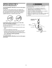
... outlet. PERMANENT WIRING CONNECTION Ground Tab Green Ground Screw Ground Wire Black Wire White Wire Black Wire 15 To reduce the risk of the motor unit: • Remove the motor unit cover screws and set the cover aside. • Remove the attached 3-prong cord. • Connect the black (line) wire to the green ground...
... outlet. PERMANENT WIRING CONNECTION Ground Tab Green Ground Screw Ground Wire Black Wire White Wire Black Wire 15 To reduce the risk of the motor unit: • Remove the motor unit cover screws and set the cover aside. • Remove the attached 3-prong cord. • Connect the black (line) wire to the green ground...
3255 Manual
Page 24
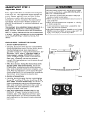
.... HOW AND WHEN TO ADJUST THE FORCES 1. If the door is hard to open ) travel , it will stop . If the door is about 3/4 of the motor unit. The door should reverse. Do not force controls beyond the minimum amount required to hold or doesn't stop, DECREASE UP (open ) force by turning the...
.... HOW AND WHEN TO ADJUST THE FORCES 1. If the door is hard to open ) travel , it will stop . If the door is about 3/4 of the motor unit. The door should reverse. Do not force controls beyond the minimum amount required to hold or doesn't stop, DECREASE UP (open ) force by turning the...
3255 Manual
Page 27
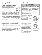
... CLOSED. However, the door will also turn off sooner. If you could result in motion. Repeat the procedure and the light will reconnect on the motor unit panel is reset to pull door open or closed if possible. The push bar light will remain on the emergency release handle and lift the...
... CLOSED. However, the door will also turn off sooner. If you could result in motion. Repeat the procedure and the light will reconnect on the motor unit panel is reset to pull door open or closed if possible. The push bar light will remain on the emergency release handle and lift the...
3255 Manual
Page 29
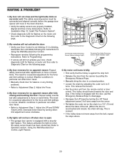
...door and stop bolt. • Release the door from the remote control or door control. The need for occasional adjustment for flashes on motor unit then refer to Adjustment Step 1, Adjust the UP and DOWN Travel Limits. Weather conditions in particular can affect door travel by turning down...safety sensors are properly installed, aligned and free of the rail. (When the door is normal. This relieves the tension. • Run the motor unit from the opener by pulling the Emergency Release Rope. • Manually bring the door to Programming. • If remote will sag. Refer to ...
...door and stop bolt. • Release the door from the remote control or door control. The need for occasional adjustment for flashes on motor unit then refer to Adjustment Step 1, Adjust the UP and DOWN Travel Limits. Weather conditions in particular can affect door travel by turning down...safety sensors are properly installed, aligned and free of the rail. (When the door is normal. This relieves the tension. • Run the motor unit from the opener by pulling the Emergency Release Rope. • Manually bring the door to Programming. • If remote will sag. Refer to ...
3255 Manual
Page 30
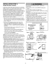
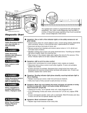
...shorten sensor wires to 1-2 ft. (30-60 cm) from motor unit. RPM Sensor = Short travel 6-8" (15-20 cm). • Unplug unit to reset. 6 FLASHES Motor Circuit Failure. Symptom: Motor unit doesn't operate. • Replace logic board because motor rarely fails. 30 If the sensor indicator lights do not glow... Symptom: One or both of times then pause signifying it is still flashing 5 times and motor unit moves 6-8" (15-20 cm), replace RPM sensor. • If motor unit doesn't operate, motor unit is not lit on door control. • Inspect door control/wires for the sensors. Momentarily...
...shorten sensor wires to 1-2 ft. (30-60 cm) from motor unit. RPM Sensor = Short travel 6-8" (15-20 cm). • Unplug unit to reset. 6 FLASHES Motor Circuit Failure. Symptom: Motor unit doesn't operate. • Replace logic board because motor rarely fails. 30 If the sensor indicator lights do not glow... Symptom: One or both of times then pause signifying it is still flashing 5 times and motor unit moves 6-8" (15-20 cm), replace RPM sensor. • If motor unit doesn't operate, motor unit is not lit on door control. • Inspect door control/wires for the sensors. Momentarily...
3255 Manual
Page 31
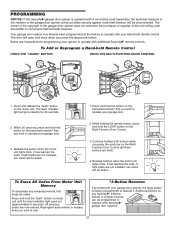
... in the receiver of the non-rolling code transmitter to circumvent that technical measure. Release the button when the motor unit lights blink. Release buttons when the motor unit lights blink. Reprogram each remote or keyless entry you wish to operate your garage door. 3. Your garage door... provides security against code-theft devices, will be heard. Continue holding the remote button, press and hold the LIGHT button on the motor unit. If light bulbs are now erased. All previous codes are not installed, two clicks will be programmed to operate other Security✚...
... in the receiver of the non-rolling code transmitter to circumvent that technical measure. Release the button when the motor unit lights blink. Release buttons when the motor unit lights blink. Reprogram each remote or keyless entry you wish to operate your garage door. 3. Your garage door... provides security against code-theft devices, will be heard. Continue holding the remote button, press and hold the LIGHT button on the motor unit. If light bulbs are now erased. All previous codes are not installed, two clicks will be programmed to operate other Security✚...
3255 Manual
Page 32
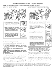
.... Continue holding the ENTER button, press and hold the ✽ button. Press the four buttons for 10 seconds. Release the # button. 2. The motor unit lights will no longer open the door. Test by pressing the four buttons for 30 seconds. 2. It can be used up one person without using... a ladder. 1. Release the button. 4. Release buttons when the motor unit lights blink. Press the temporary 4-digit PIN you have chosen, then press Enter. To set to close the door even after it may authorize access...
.... Continue holding the ENTER button, press and hold the ✽ button. Press the four buttons for 10 seconds. Release the # button. 2. The motor unit lights will no longer open the door. Test by pressing the four buttons for 30 seconds. 2. It can be used up one person without using... a ladder. 1. Release the button. 4. Release buttons when the motor unit lights blink. Press the temporary 4-digit PIN you have chosen, then press Enter. To set to close the door even after it may authorize access...
3255 Manual
Page 34
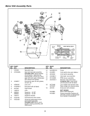
... hardware kit (includes screws not designated by a number in illustration) 34 High voltage wire harness assy. Complete with: Logic board and end panel with : Motor, worm, bracket, bearing assembly and RPM sensor KEY PART NO. End panel with all labels Low voltage wire harness assy. NO. 12 41A5525-24 13...cup assembly RPM sensor assembly Receiver logic board assy. UP DN Drive Gear Center Limit Contact (Up) Contact Grey Wire Yellow Wire KEY PART NO. Motor Unit Assembly Parts 3 6 1 4 18 2 17 5 7 8 11 13 9 14 12 10 16 19 15 Brown Wire (Down) Contact LIMIT SWITCH ASSY...
... hardware kit (includes screws not designated by a number in illustration) 34 High voltage wire harness assy. Complete with: Logic board and end panel with : Motor, worm, bracket, bearing assembly and RPM sensor KEY PART NO. End panel with all labels Low voltage wire harness assy. NO. 12 41A5525-24 13...cup assembly RPM sensor assembly Receiver logic board assy. UP DN Drive Gear Center Limit Contact (Up) Contact Grey Wire Yellow Wire KEY PART NO. Motor Unit Assembly Parts 3 6 1 4 18 2 17 5 7 8 11 13 9 14 12 10 16 19 15 Brown Wire (Down) Contact LIMIT SWITCH ASSY...
3255 Manual
Page 36
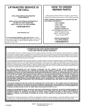
... THE CHAMBERLAIN GROUP, INC. Country Club Road Tucson, Arizona 85706 SERVICE INFORMATION TOLL FREE NUMBER: 1-800-528-9131 LIFTMASTER ONE-YEAR LIMITED WARRANTY FOUR-YEAR MOTOR LIMITED WARRANTY The Chamberlain Group, Inc. ("Seller") warrants to the first retail purchaser of this product is originally installed... MAINTENANCE, UNAUTHORIZED REPAIRS OR ANY ALTERATIONS TO THIS PRODUCT), LABOR CHARGES FOR REINSTALLING A REPAIRED OR REPLACED UNIT, REPLACEMENT OF BATTERIES AND LIGHT BULBS OR UNITS INSTALLED FOR NON-RESIDENTIAL USE. ANY SERVICE CALL THAT DETERMINES THE PROBLEM HAS BEEN CAUSED BY ANY OF...
... THE CHAMBERLAIN GROUP, INC. Country Club Road Tucson, Arizona 85706 SERVICE INFORMATION TOLL FREE NUMBER: 1-800-528-9131 LIFTMASTER ONE-YEAR LIMITED WARRANTY FOUR-YEAR MOTOR LIMITED WARRANTY The Chamberlain Group, Inc. ("Seller") warrants to the first retail purchaser of this product is originally installed... MAINTENANCE, UNAUTHORIZED REPAIRS OR ANY ALTERATIONS TO THIS PRODUCT), LABOR CHARGES FOR REINSTALLING A REPAIRED OR REPLACED UNIT, REPLACEMENT OF BATTERIES AND LIGHT BULBS OR UNITS INSTALLED FOR NON-RESIDENTIAL USE. ANY SERVICE CALL THAT DETERMINES THE PROBLEM HAS BEEN CAUSED BY ANY OF...


