
Service Manual
Page 25
...500-sheet dual trays (Models 2450, 2455 and 3455) 2000 Sheet High Capacity Feeder Envelope feeder Duplex option Hard Disk - 1.4 GB (Models 1250, 1620, 1650, 2420 and 2450) Hard Disk - 2.1 GB (Models 1255, 1625, 1855, 2455 and 3455) Forms Hard Disk - 2.1 GB Infrared Adapter Kiosk Adapter Output Expander... (Models 1650, 1855, 2450, 2455 and 3455) General Information 1-4 Memory options of 4MB, 8MB, 16MB and 32MB Flash memory options of 4MB and 8MB Integrated network ...
...500-sheet dual trays (Models 2450, 2455 and 3455) 2000 Sheet High Capacity Feeder Envelope feeder Duplex option Hard Disk - 1.4 GB (Models 1250, 1620, 1650, 2420 and 2450) Hard Disk - 2.1 GB (Models 1255, 1625, 1855, 2455 and 3455) Forms Hard Disk - 2.1 GB Infrared Adapter Kiosk Adapter Output Expander... (Models 1650, 1855, 2450, 2455 and 3455) General Information 1-4 Memory options of 4MB, 8MB, 16MB and 32MB Flash memory options of 4MB and 8MB Integrated network ...

Service Manual
Page 52
.... Go to "Print Quality - Go to operate. Light Print" on page 2-92. 4059-XXX Symptom Tables Symptom Table - Duplex Option installed Fuser Solenoid (Models 1620/1650/2420/2450/ 3455)fails to "Print Quality - Blank page Print quality - Go to the "Paper Feed Service Check" on page 2-74. Go to the "Operator...
.... Go to "Print Quality - Go to operate. Light Print" on page 2-92. 4059-XXX Symptom Tables Symptom Table - Duplex Option installed Fuser Solenoid (Models 1620/1650/2420/2450/ 3455)fails to "Print Quality - Blank page Print quality - Go to the "Paper Feed Service Check" on page 2-74. Go to the "Operator...
Service Manual
Page 78
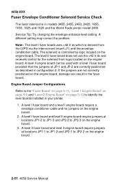
... to JP2-3 on the engine board. 2-51 4059 Service Manual If the jumpers are correctly positioned as described in models 3455, 2455, 2450, 2420, 1855, 1650, 1625 and 1620 and the World Trade printer model 2450. 4059-XXX Fuser Envelope Conditioner Solenoid Service Check The fuser solenoid is in configuration 2. A level...
... to JP2-3 on the engine board. 2-51 4059 Service Manual If the jumpers are correctly positioned as described in models 3455, 2455, 2450, 2420, 1855, 1650, 1625 and 1620 and the World Trade printer model 2450. 4059-XXX Fuser Envelope Conditioner Solenoid Service Check The fuser solenoid is in configuration 2. A level...

Service Manual
Page 103
The voltage measures approximately +5 V dc. 4059-XXX FRU 4 Operator Panel all diamonds, No Beeps 5 Operator Panel all diamonds on a 2450 or 1650 (the 1250 has only one slot), switch the non operating option to one of the other option slots to isolate the failure. This condition causes ...
The voltage measures approximately +5 V dc. 4059-XXX FRU 4 Operator Panel all diamonds, No Beeps 5 Operator Panel all diamonds on a 2450 or 1650 (the 1250 has only one slot), switch the non operating option to one of the other option slots to isolate the failure. This condition causes ...

Service Manual
Page 104
...Disk Test is unusable. This test leaves the hard disk unformatted. 4059-XXX Hard Disk Option Service Tip: The Optra S printers support one hard disk option is installed. • 1.4 GB - 1250/1620/1650/2420/2450 • 2.1 GB - 1255/1625/1855/2455/3455 Check to make sure only one hard disk option... Menu when a problem is installed in slot x on page 3-2 is used to make sure the fixed disk and the fixed disk board are servicing a 1650, 1855, 2420, 2450 or 2455 and the network card works in another slot, replace the interconnect board. 2-77 4059 Service Manual Network Card X A ...
...Disk Test is unusable. This test leaves the hard disk unformatted. 4059-XXX Hard Disk Option Service Tip: The Optra S printers support one hard disk option is installed. • 1.4 GB - 1250/1620/1650/2420/2450 • 2.1 GB - 1255/1625/1855/2455/3455 Check to make sure only one hard disk option... Menu when a problem is installed in slot x on page 3-2 is used to make sure the fixed disk and the fixed disk board are servicing a 1650, 1855, 2420, 2450 or 2455 and the network card works in another slot, replace the interconnect board. 2-77 4059 Service Manual Network Card X A ...

Service Manual
Page 161
... to the fuser control board connector J2-1 and J2-2 and from J2 to J1-2 and J1-3 on the model 2420, 2450, 2455, 3455, 1620, 1625, 1650 and 1855. The model 3455 printer fuser temperature is the fuser frame which has the exit sensor mounted on the board) and the envelope conditioner.... U9 monitors the change in thermistor resistance and sends a signal (HEATON) from 0 V dc (lamp On) to control the fuser lamp. The model 1620, 1625 and 1650 printer fuser temperature is connected to the cathode of the fuser hot roll increases. The HEATON signal from CN3-9 varies from J20-A25 through the...
... to the fuser control board connector J2-1 and J2-2 and from J2 to J1-2 and J1-3 on the model 2420, 2450, 2455, 3455, 1620, 1625, 1650 and 1855. The model 3455 printer fuser temperature is the fuser frame which has the exit sensor mounted on the board) and the envelope conditioner.... U9 monitors the change in thermistor resistance and sends a signal (HEATON) from 0 V dc (lamp On) to control the fuser lamp. The model 1620, 1625 and 1650 printer fuser temperature is connected to the cathode of the fuser hot roll increases. The HEATON signal from CN3-9 varies from J20-A25 through the...

Service Manual
Page 166
... GAP ADJUST 4. Enter the Diagnostic Mode 2. Adjust the gap setting by using the Menu < > button to minimum gap. Printer Model 2420/2450/2455 1620/1625/1650/1855 3455 Solenoid Air Gap 4.4 mm (.170 inch) 3.9 mm (.153 inch) 4.8 mm (.153 inch) Gap Adjustment The gap adjustment allows you replace the fuser solenoid...
... GAP ADJUST 4. Enter the Diagnostic Mode 2. Adjust the gap setting by using the Menu < > button to minimum gap. Printer Model 2420/2450/2455 1620/1625/1650/1855 3455 Solenoid Air Gap 4.4 mm (.170 inch) 3.9 mm (.153 inch) 4.8 mm (.153 inch) Gap Adjustment The gap adjustment allows you replace the fuser solenoid...
Service Manual
Page 210
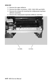
Remove the multipurpose tray/lower deflector assembly. 4-47 4059 Service Manual Remove the screws (A) mounting the multipurpose tray/lower deflector assembly. 5. 4059-XXX 2. Remove the paper out sensor. (1250, 1620,1650 and 2420) 4. Remove the upper deflector. 3.
Remove the multipurpose tray/lower deflector assembly. 4-47 4059 Service Manual Remove the screws (A) mounting the multipurpose tray/lower deflector assembly. 5. 4059-XXX 2. Remove the paper out sensor. (1250, 1620,1650 and 2420) 4. Remove the upper deflector. 3.

Service Manual
Page 239
4059-XXX Interconnect Board Connector J1 Fuser Solenoid (Model1620/1625/ 1650/1855/2420/2450/ 2455) J2 LVPS J3 LVPS J4 Autoconnect Top (Model1620/1625/ 1650/1855/2420/2450/ 2455) Pin No. 1 2 1 2 3 4 5 6 7 8 9 10 1 2 3 4 5 6 7 8 1 2 3 4 Signal +42 V dc Ground +42 V dc Heaton Xeroxing +24 V dc +24 V dc +24 V dc Ground Ground Ground Ground Ground Ground Ground Ground +5 V dc +5 V dc +5 V dc +5 V dc +24 V dc Ground +5 V dc Fused Ground Connector Locations 5-14
4059-XXX Interconnect Board Connector J1 Fuser Solenoid (Model1620/1625/ 1650/1855/2420/2450/ 2455) J2 LVPS J3 LVPS J4 Autoconnect Top (Model1620/1625/ 1650/1855/2420/2450/ 2455) Pin No. 1 2 1 2 3 4 5 6 7 8 9 10 1 2 3 4 5 6 7 8 1 2 3 4 Signal +42 V dc Ground +42 V dc Heaton Xeroxing +24 V dc +24 V dc +24 V dc Ground Ground Ground Ground Ground Ground Ground Ground +5 V dc +5 V dc +5 V dc +5 V dc +24 V dc Ground +5 V dc Fused Ground Connector Locations 5-14
Service Manual
Page 240
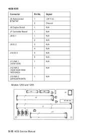
4059-XXX Connector J5 Autoconnect BTM/FNT J6 Engine Board J7 Controller Board J8 ID-1 J9 ID-2 J10 ID-3 J11 INA 1 (1250/1255) J12 INA 2 (1620/1625/1650/ 1855/2420) J13 INA 3 (2450/2455/3455) Pin No. 1 2 1 1 1 2 3 4 5 6 1 1 1 Models 1250 and 1255 Signal +24 V dc Ground N/A N/A N/A N/A N/A N/A N/A N/A N/A N/A N/A 5-15 4059 Service Manual
4059-XXX Connector J5 Autoconnect BTM/FNT J6 Engine Board J7 Controller Board J8 ID-1 J9 ID-2 J10 ID-3 J11 INA 1 (1250/1255) J12 INA 2 (1620/1625/1650/ 1855/2420) J13 INA 3 (2450/2455/3455) Pin No. 1 2 1 1 1 2 3 4 5 6 1 1 1 Models 1250 and 1255 Signal +24 V dc Ground N/A N/A N/A N/A N/A N/A N/A N/A N/A N/A N/A 5-15 4059 Service Manual

Service Manual
Page 241
Connector Locations 5-16 4059-XXX Models 1620, 1625, 1650, 1855, 2420, 2450, 2455 and 3455 • Models 1650, 1855, and 2420 do not have connector J13. • Models 1620 and 1625 have a jumper on J10 between the center pin and pin 5. • Model ...
Connector Locations 5-16 4059-XXX Models 1620, 1625, 1650, 1855, 2420, 2450, 2455 and 3455 • Models 1650, 1855, and 2420 do not have connector J13. • Models 1620 and 1625 have a jumper on J10 between the center pin and pin 5. • Model ...
Service Manual
Page 253
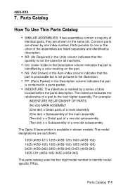
Parts peculiar to identify model specific FRUs. The model designations are as follows: 1250 (4059-121) 1255 (4059-125) 1620 (4059-162) 1625 (4059-165) 1650 (4059-160) 1855 (4059-185) 2420 (4059-242) 2450 (4059-240) 2455 (4059-245) 1855-C01 (4059-185) 3455 (4059-345) The parts ... part to the next higher assembly. The indenture indicates the relationship of identical parts, they are shown by a series of a one-dot subassembly The Optra S laser printer is available in a parts packet. • INDENTURE: The indenture is contained in eleven models. Parts Catalog 7-1 4059-XXX 7.
Parts peculiar to identify model specific FRUs. The model designations are as follows: 1250 (4059-121) 1255 (4059-125) 1620 (4059-162) 1625 (4059-165) 1650 (4059-160) 1855 (4059-185) 2420 (4059-242) 2450 (4059-240) 2455 (4059-245) 1855-C01 (4059-185) 3455 (4059-345) The parts ... part to the next higher assembly. The indenture indicates the relationship of identical parts, they are shown by a series of a one-dot subassembly The Optra S laser printer is available in a parts packet. • INDENTURE: The indenture is contained in eleven models. Parts Catalog 7-1 4059-XXX 7.
Service Manual
Page 255
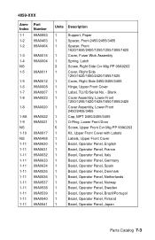
Blank 1 Cover Assembly, Lower Front 1250/1255/1620/1625/1650/1855/2420 1 Cover Assembly, Lower Front 2450/2455/3455 1 Cap, MPT 2450/2455/3455 1 O-Ring, Lower Front Door 5 Screw, Upper Front Cvr Mtg PP 99A0263 1 ... 99A0458 99A0630 99A0631 99A0632 99A0633 99A0634 99A0535 99A0536 99A0537 99A0538 99A0539 99A0540 99A0541 Units Description 1 Support, Paper 1 Spacer, Front 2450/2455/3455 1 Spacer, Front 1620/1650/2420/1250/1255/1855/1625 1 Cover, Fuser Wick Assembly 1 Spring, Latch 3 Screw, Right Side Cvr Mtg PP 99A0263 1 Cover, RIght Side 1250/1620...
Blank 1 Cover Assembly, Lower Front 1250/1255/1620/1625/1650/1855/2420 1 Cover Assembly, Lower Front 2450/2455/3455 1 Cap, MPT 2450/2455/3455 1 O-Ring, Lower Front Door 5 Screw, Upper Front Cvr Mtg PP 99A0263 1 ... 99A0458 99A0630 99A0631 99A0632 99A0633 99A0634 99A0535 99A0536 99A0537 99A0538 99A0539 99A0540 99A0541 Units Description 1 Support, Paper 1 Spacer, Front 2450/2455/3455 1 Spacer, Front 1620/1650/2420/1250/1255/1855/1625 1 Cover, Fuser Wick Assembly 1 Spring, Latch 3 Screw, Right Side Cvr Mtg PP 99A0263 1 Cover, RIght Side 1250/1620...
Service Manual
Page 257
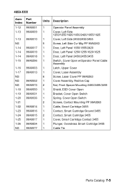
... NS 99A0003 99A0013 99A0552 99A0573 99A0550 99A0031 99A0036 99A0814 99A0816 99A0815 99A0817 99A0834 99A0577 Units Description 1 Operator Panel Assembly 1 Cover, Left Side 1250/1255/1620/1650/2420/1855/1625 1 Cover, Left Side 2450/2455/3455 5 Screw, Left Side Cvr Mtg PP 99A0263 1 Door, Left Panel... 1650/1855/2420 1 Door, Left Panel 1250/1255/1620/1625 1 Door, Left Panel 2450/2455/3455 1 Switch, Cover Open w/Operator Panel Cable Assembly 1 Latch, Upper Cover 1 ...
... NS 99A0003 99A0013 99A0552 99A0573 99A0550 99A0031 99A0036 99A0814 99A0816 99A0815 99A0817 99A0834 99A0577 Units Description 1 Operator Panel Assembly 1 Cover, Left Side 1250/1255/1620/1650/2420/1855/1625 1 Cover, Left Side 2450/2455/3455 5 Screw, Left Side Cvr Mtg PP 99A0263 1 Door, Left Panel... 1650/1855/2420 1 Door, Left Panel 1250/1255/1620/1625 1 Door, Left Panel 2450/2455/3455 1 Switch, Cover Open w/Operator Panel Cable Assembly 1 Latch, Upper Cover 1 ...
Service Manual
Page 259
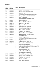
...1 Support, Cross Brace 1 Spacer, Front 2450/2455/3455 1 Spacer, Front 1250/1255/1620/1650/2420/1855/1625 1 Duct, Left Stacker 2450/2455/3455 1 Duct, Left Stacker 1250/1620/1650/2420/1855/1625 1 Duct, Main Body 1 Support, Left Lower Stacker 1 Duct, LVPS Left ... Machine Mounting 1 Transfer Plate Assembly 1 Transfer Plate Assembly 3455 1 Plate Assembly, Stacker Ground 2450/2455/3455 1 Support, Right Stacker 1250/1255/1620/1650/2420/1855/1625 1 Right Sideframe 1 Track, Cartridge Guide RH 1 Fan, Auxiliary 2420/2450/3455 1 Contact Kit PP 99A0585 3 o Contact, Doctor...
...1 Support, Cross Brace 1 Spacer, Front 2450/2455/3455 1 Spacer, Front 1250/1255/1620/1650/2420/1855/1625 1 Duct, Left Stacker 2450/2455/3455 1 Duct, Left Stacker 1250/1620/1650/2420/1855/1625 1 Duct, Main Body 1 Support, Left Lower Stacker 1 Duct, LVPS Left ... Machine Mounting 1 Transfer Plate Assembly 1 Transfer Plate Assembly 3455 1 Plate Assembly, Stacker Ground 2450/2455/3455 1 Support, Right Stacker 1250/1255/1620/1650/2420/1855/1625 1 Right Sideframe 1 Track, Cartridge Guide RH 1 Fan, Auxiliary 2420/2450/3455 1 Contact Kit PP 99A0585 3 o Contact, Doctor...

Service Manual
Page 261
...1 Deflector, Upper PF 1 Deflector, Inner 1 Frame, EP Module 1 Sensor, Input 1 Spring, PA Out Activate 1 Cover, Gap 1620/1625/1650/1855/2420/2450/2455 1 Cover, Gap 3455 1 Shield, ESD Assembly with label 1 Left Side Frame 1 Board, Input Tray (ITC) 1 Frame Extension...Gear Release 1 Bracket, Counterbalance Hinge Spring 1 Spring, Counterbalance 17 Screw PP 99A0263 1 Fan, Main 1 Fan, Main 3455 1 Flag Kit, Standard Bin Level 1650/1855/2420 1 Flag Kit, Standard Bin Level 2450/2455/3455 1 Flag, Standard Bin Level 1855-C01 1 Flap, 250 Paper Output Bin 1855-C01 1 ...
...1 Deflector, Upper PF 1 Deflector, Inner 1 Frame, EP Module 1 Sensor, Input 1 Spring, PA Out Activate 1 Cover, Gap 1620/1625/1650/1855/2420/2450/2455 1 Cover, Gap 3455 1 Shield, ESD Assembly with label 1 Left Side Frame 1 Board, Input Tray (ITC) 1 Frame Extension...Gear Release 1 Bracket, Counterbalance Hinge Spring 1 Spring, Counterbalance 17 Screw PP 99A0263 1 Fan, Main 1 Fan, Main 3455 1 Flag Kit, Standard Bin Level 1650/1855/2420 1 Flag Kit, Standard Bin Level 2450/2455/3455 1 Flag, Standard Bin Level 1855-C01 1 Flap, 250 Paper Output Bin 1855-C01 1 ...
Service Manual
Page 263
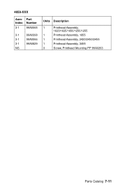
4059-XXX AsmIndex 3-1 Part Number 99A0065 3-1 99A0398 3-1 99A0066 3-1 99A0829 NS Units Description 1 Printhead Assembly, 1620/1625/1650/1250/1255 1 Printhead Assembly, 1855 1 Printhead Assembly, 2420/2450/2455 1 Printhead Assembly, 3455 3 Screw, Printhead Mounting PP 99A0263 Parts Catalog 7-11
4059-XXX AsmIndex 3-1 Part Number 99A0065 3-1 99A0398 3-1 99A0066 3-1 99A0829 NS Units Description 1 Printhead Assembly, 1620/1625/1650/1250/1255 1 Printhead Assembly, 1855 1 Printhead Assembly, 2420/2450/2455 1 Printhead Assembly, 3455 3 Screw, Printhead Mounting PP 99A0263 Parts Catalog 7-11

Service Manual
Page 267
...99A0074 Units Description 1 Screw, Socket Set M4X5 mm 1250/1255/1650/1620/2420/1855/1625 1 Arm Assembly, MPT 1620/1650/1250/1255/2420/1855/1625 1 Pick Roll Assembly 1250/1255/1620/1650/2420/1855/1625 1 Spring Assembly, Separator 1620/1650/1250/1255/2420/1855/1625 1 MPT Pad Assembly Kit o ... 99A0263 2450 2 Screw, Lower Deflector Mounting 12mm PP 99A0263 1250/1255/1620/1650/2420/1855/1625 1 O-Ring, Lower Front Door 1 Flag, MPT Paper Out 1250/1255/1650/1620/2420/1855/1625 1 Plate Assembly, MPT 1620/1650/1250/1255/2420/1855/1625 1 Sensor, MPT Paper Out 1250/1255/1620...
...99A0074 Units Description 1 Screw, Socket Set M4X5 mm 1250/1255/1650/1620/2420/1855/1625 1 Arm Assembly, MPT 1620/1650/1250/1255/2420/1855/1625 1 Pick Roll Assembly 1250/1255/1620/1650/2420/1855/1625 1 Spring Assembly, Separator 1620/1650/1250/1255/2420/1855/1625 1 MPT Pad Assembly Kit o ... 99A0263 2450 2 Screw, Lower Deflector Mounting 12mm PP 99A0263 1250/1255/1620/1650/2420/1855/1625 1 O-Ring, Lower Front Door 1 Flag, MPT Paper Out 1250/1255/1650/1620/2420/1855/1625 1 Plate Assembly, MPT 1620/1650/1250/1255/2420/1855/1625 1 Sensor, MPT Paper Out 1250/1255/1620...

Service Manual
Page 271
... 7-1 99A0502 7-2 99A0109 7-2 99A0110 NS 99A0104 NS 99A0107 NS NS 99A0891 NS 99A0921 Units Description 1 Deflector Assembly, Inner 500 2450/2455 1 Deflector Assembly, Inner 250 1620/1650/1250/1255/2420/1855/1625 1 Deflector Assembly, Inner 250 1855-C01 1 Deflector Assembly Outer 500 2450/2455 1 Deflector Assembly Outer 250 1620...
... 7-1 99A0502 7-2 99A0109 7-2 99A0110 NS 99A0104 NS 99A0107 NS NS 99A0891 NS 99A0921 Units Description 1 Deflector Assembly, Inner 500 2450/2455 1 Deflector Assembly, Inner 250 1620/1650/1250/1255/2420/1855/1625 1 Deflector Assembly, Inner 250 1855-C01 1 Deflector Assembly Outer 500 2450/2455 1 Deflector Assembly Outer 250 1620...
Service Manual
Page 275
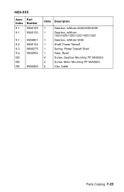
4059-XXX AsmIndex 9-1 9-1 Part Number 99A0129 99A0130 9-1 99A0801 9-2 99A0134 9-3 99A0275 9-4 99A0954 NS NS NS 99A0260 Units Description 1 Gearbox, w/Motor 2420/2450/2455 1 Gearbox, w/Motor 1620/1650/1250/1255/1855/1625 1 Gearbox, w/Motor 3455 1 Shaft, Power Takeoff 1 Spring, Power Takeoff Shaft 1 Gear, Bevel 4 Screw, Gearbox Mounting PP 99A0263 3 Screw, Motor Mounting PP 99A0263 2 Clip, Cable Parts Catalog 7-23
4059-XXX AsmIndex 9-1 9-1 Part Number 99A0129 99A0130 9-1 99A0801 9-2 99A0134 9-3 99A0275 9-4 99A0954 NS NS NS 99A0260 Units Description 1 Gearbox, w/Motor 2420/2450/2455 1 Gearbox, w/Motor 1620/1650/1250/1255/1855/1625 1 Gearbox, w/Motor 3455 1 Shaft, Power Takeoff 1 Spring, Power Takeoff Shaft 1 Gear, Bevel 4 Screw, Gearbox Mounting PP 99A0263 3 Screw, Motor Mounting PP 99A0263 2 Clip, Cable Parts Catalog 7-23