Service Manual
Page 4
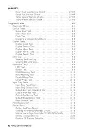
... Base Sensor Test 3-17 Print Registration 3-18 Printer Setup 3-19 Setting the Page Count 3-19 Viewing the Permanent Page Count 3-19 Maintenance Page Count (2420/2450/2455/3455) . . . . . 3-20 Setting Configuration ID 3-20 Restore EP Factory Defaults 3-21 iv 4059 Service Manual 4059-XXX Smart Cartridge Service Check 2-102 Serial Port...
... Base Sensor Test 3-17 Print Registration 3-18 Printer Setup 3-19 Setting the Page Count 3-19 Viewing the Permanent Page Count 3-19 Maintenance Page Count (2420/2450/2455/3455) . . . . . 3-20 Setting Configuration ID 3-20 Restore EP Factory Defaults 3-21 iv 4059 Service Manual 4059-XXX Smart Cartridge Service Check 2-102 Serial Port...

Service Manual
Page 6
... 5-22 Output Expander Control Board - Top 5-21 Output Expander Control Board - Level 2 DC Motor . . . . 5-24 Preventive Maintenance 6-1 Safety Inspection Guide 6-1 Lubrication Specifications 6-1 Scheduled Maintenance (2420/2450/2455/3455 6-2 vi 4059 Service Manual 4059-XXX Inner EMC Shield 4-35 Inner Paper Deflector Assembly 4-36 Integrated Tray Compensator Assembly 4-37 Integrated Tray Compensator...
... 5-22 Output Expander Control Board - Top 5-21 Output Expander Control Board - Level 2 DC Motor . . . . 5-24 Preventive Maintenance 6-1 Safety Inspection Guide 6-1 Lubrication Specifications 6-1 Scheduled Maintenance (2420/2450/2455/3455 6-2 vi 4059 Service Manual 4059-XXX Inner EMC Shield 4-35 Inner Paper Deflector Assembly 4-36 Integrated Tray Compensator Assembly 4-37 Integrated Tray Compensator...

Service Manual
Page 25
... options are not available in your point of A5, letter, and legal size. 250 Sheet Special Media Tray Assembly 500/500-sheet dual trays (Models 2450, 2455 and 3455) 2000 Sheet High Capacity Feeder Envelope feeder Duplex option Hard Disk - 1.4 GB (Models 1250, 1620, 1650, 2420 and... Disk - 2.1 GB (Models 1255, 1625, 1855, 2455 and 3455) Forms Hard Disk - 2.1 GB Infrared Adapter Kiosk Adapter Output Expander (Models 1650, 1855, 2450, 2455 and 3455) General Information 1-4 Some options are available. Memory options of 4MB, 8MB, 16MB and 32MB Flash memory options of 4MB and 8MB Integrated ...
... options are not available in your point of A5, letter, and legal size. 250 Sheet Special Media Tray Assembly 500/500-sheet dual trays (Models 2450, 2455 and 3455) 2000 Sheet High Capacity Feeder Envelope feeder Duplex option Hard Disk - 1.4 GB (Models 1250, 1620, 1650, 2420 and... Disk - 2.1 GB (Models 1255, 1625, 1855, 2455 and 3455) Forms Hard Disk - 2.1 GB Infrared Adapter Kiosk Adapter Output Expander (Models 1650, 1855, 2450, 2455 and 3455) General Information 1-4 Some options are available. Memory options of 4MB, 8MB, 16MB and 32MB Flash memory options of 4MB and 8MB Integrated ...

Service Manual
Page 47
Press Go to "Scheduled Maintenance (2420/2450/2455/ 3455)" on page 6-2. 4059-XXX User Error Message 80 Scheduled Maintenance 81 Engine Code CRC Failure 88 Toner Low Explanation The operator panel displays ...
Press Go to "Scheduled Maintenance (2420/2450/2455/ 3455)" on page 6-2. 4059-XXX User Error Message 80 Scheduled Maintenance 81 Engine Code CRC Failure 88 Toner Low Explanation The operator panel displays ...

Service Manual
Page 51
... position if installed. - The operator panel LED starts blinking. 12. The main drive motor turns on . 2. Diagnostic Information 2-24 The LED comes on . 9. Models 2420, 2450 2455 and 3455 only - The auxiliary fan turns on the display. The operator panel displays one and a half row of the base printer by observing...
... position if installed. - The operator panel LED starts blinking. 12. The main drive motor turns on . 2. Diagnostic Information 2-24 The LED comes on . 9. Models 2420, 2450 2455 and 3455 only - The auxiliary fan turns on the display. The operator panel displays one and a half row of the base printer by observing...

Service Manual
Page 52
...101. 2-25 4059 Service Manual Blank Page" on page 2-74. 4059-XXX Symptom Tables Symptom Table - Base Printer Symptom Auxiliary Fan (2420/2450/2455/ 3455) fails to "Print Quality - Base printer or Integrated 250 Paper Tray Paper jams at exit of Redrive Assembly - Replace the ...Light Print" on page 2-35. Operator Panel - Paper jams at exit of Redrive Assembly - Duplex Option installed Fuser Solenoid (Models 1620/1650/2420/2450/ 3455)fails to "Print Quality - Black page Print quality - Go to the "Fuser Envelope Conditioner Solenoid Service Check" on page 2-86. ...
...101. 2-25 4059 Service Manual Blank Page" on page 2-74. 4059-XXX Symptom Tables Symptom Table - Base Printer Symptom Auxiliary Fan (2420/2450/2455/ 3455) fails to "Print Quality - Base printer or Integrated 250 Paper Tray Paper jams at exit of Redrive Assembly - Replace the ...Light Print" on page 2-35. Operator Panel - Paper jams at exit of Redrive Assembly - Duplex Option installed Fuser Solenoid (Models 1620/1650/2420/2450/ 3455)fails to "Print Quality - Black page Print quality - Go to the "Fuser Envelope Conditioner Solenoid Service Check" on page 2-86. ...

Service Manual
Page 74
... the engine board. Main Fan Service Check Check the cable connections at the main fan assembly. Fan does not run or is in models 2420, 2450, 2455 and 3455. If incorrect, replace the fan and cable assembly. If correct, replace the fan assembly. If incorrect, replace the cable. 2-47 4059 Service...
... the engine board. Main Fan Service Check Check the cable connections at the main fan assembly. Fan does not run or is in models 2420, 2450, 2455 and 3455. If incorrect, replace the fan and cable assembly. If correct, replace the fan assembly. If incorrect, replace the cable. 2-47 4059 Service...

Service Manual
Page 78
... the fuser board. A level II engine board can result to identify the level boards installed in models 3455, 2455, 2450, 2420, 1855, 1650, 1625 and 1620 and the World Trade printer model 2450. The solenoid is controlled by logic located on the engine board. A level I fuser board and a level I fuser board uses...
... the fuser board. A level II engine board can result to identify the level boards installed in models 3455, 2455, 2450, 2420, 1855, 1650, 1625 and 1620 and the World Trade printer model 2450. The solenoid is controlled by logic located on the engine board. A level I fuser board and a level I fuser board uses...

Service Manual
Page 103
... options slots on the interconnect board on page 3-3. If the Memory SIMM is correctly installed not broken or damaged then run the "Flash Test" on a 2450 or 1650 (the 1250 has only one slot), switch the non operating option to one of the test page and check to make sure a SIMM...
... options slots on the interconnect board on page 3-3. If the Memory SIMM is correctly installed not broken or damaged then run the "Flash Test" on a 2450 or 1650 (the 1250 has only one slot), switch the non operating option to one of the test page and check to make sure a SIMM...
Service Manual
Page 104
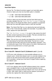
... no problem, contact your next level of test. Check to make sure the fixed disk and the fixed disk board are servicing a 1650, 1855, 2420, 2450 or 2455 and the network card works in the socket on the disk size. If you are correctly installed. Note: This can be performed on... or testing section. Note: The Quick Disk Test is unusable. 4059-XXX Hard Disk Option Service Tip: The Optra S printers support one hard disk option is installed. • 1.4 GB - 1250/1620/1650/2420/2450 • 2.1 GB - 1255/1625/1855/2455/3455 Check to make sure only one hard disk option. This is...
... no problem, contact your next level of test. Check to make sure the fixed disk and the fixed disk board are servicing a 1650, 1855, 2420, 2450 or 2455 and the network card works in the socket on the disk size. If you are correctly installed. Note: This can be performed on... or testing section. Note: The Quick Disk Test is unusable. 4059-XXX Hard Disk Option Service Tip: The Optra S printers support one hard disk option is installed. • 1.4 GB - 1250/1620/1650/2420/2450 • 2.1 GB - 1255/1625/1855/2455/3455 Check to make sure only one hard disk option. This is...
Service Manual
Page 132
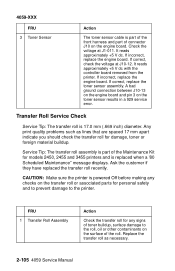
... on the engine board. Replace the transfer roll as lines that are spaced 17 mm apart indicate you should check the transfer roll for models 2450, 2455 and 3455 printers and is replaced when a '80 Scheduled Maintenance" message displays. It reads approximately +5 V dc with the controller board removed from the printer...
... on the engine board. Replace the transfer roll as lines that are spaced 17 mm apart indicate you should check the transfer roll for models 2450, 2455 and 3455 printers and is replaced when a '80 Scheduled Maintenance" message displays. It reads approximately +5 V dc with the controller board removed from the printer...
Service Manual
Page 153
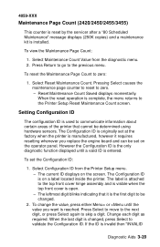
... is attached to the top front cover hinge assembly and is visible when the top front cover is installed. 4059-XXX Maintenance Page Count (2420/2450/2455/3455) This counter is reset by the servicer after a "80 Scheduled Maintenance" message displays (250K copies) and a maintenance kit is open. - To reset the...
... is attached to the top front cover hinge assembly and is visible when the top front cover is installed. 4059-XXX Maintenance Page Count (2420/2450/2455/3455) This counter is reset by the servicer after a "80 Scheduled Maintenance" message displays (250K copies) and a maintenance kit is open. - To reset the...

Service Manual
Page 161
...the thermistor is proportional to the fuser temperature and varies from approximately 2.0 V dc (cold) to 2.3 V dc (warm during continuous printing. The model 2420, 2450 and 2455 printer fuser temperature is 185.5 degrees C while printing at 600 dpi and 145.5 degrees C while printing at 1200 dpi. These voltages are connected...the hot roll, backup roll, and associated parts as well as the temperature of an Opto triac to J2-6 and J2-7 on the model 2420, 2450, 2455, 3455, 1620, 1625, 1650 and 1855. The second part of the assembly is 270 degrees C while printing at 600 dpi and 170 ...
...the thermistor is proportional to the fuser temperature and varies from approximately 2.0 V dc (cold) to 2.3 V dc (warm during continuous printing. The model 2420, 2450 and 2455 printer fuser temperature is 185.5 degrees C while printing at 600 dpi and 145.5 degrees C while printing at 1200 dpi. These voltages are connected...the hot roll, backup roll, and associated parts as well as the temperature of an Opto triac to J2-6 and J2-7 on the model 2420, 2450, 2455, 3455, 1620, 1625, 1650 and 1855. The second part of the assembly is 270 degrees C while printing at 600 dpi and 170 ...

Service Manual
Page 166
Printer Model 2420/2450/2455 1620/1625/1650/1855 3455 Solenoid Air Gap 4.4 mm (.170 inch) 3.9 mm (.153 inch) 4.8 mm (.153 inch) Gap Adjustment The gap adjustment allows you ...
Printer Model 2420/2450/2455 1620/1625/1650/1855 3455 Solenoid Air Gap 4.4 mm (.170 inch) 3.9 mm (.153 inch) 4.8 mm (.153 inch) Gap Adjustment The gap adjustment allows you ...

Service Manual
Page 187
Remove the right cover. 2. Note the routing of the auxiliary fan cable (A) and remove the fan (B). 4059-XXX Fans Auxiliary Fan (Models 2420/2450/2455/3455) 1. Disconnect the auxiliary fan cable from the engine board at connector J7. 5. Remove the inner EMC shield. 3. Repair Information 4-24 Remove the fuser wiper cover. 4.
Remove the right cover. 2. Note the routing of the auxiliary fan cable (A) and remove the fan (B). 4059-XXX Fans Auxiliary Fan (Models 2420/2450/2455/3455) 1. Disconnect the auxiliary fan cable from the engine board at connector J7. 5. Remove the inner EMC shield. 3. Repair Information 4-24 Remove the fuser wiper cover. 4.

Service Manual
Page 230
J5 Printhead 1 2 3 4 5 6 7 8 9 10 J6 Output Level Sensor 1 2 3 4 5 J7 Auxiliary Fan 1 (Model 2420/2450/2455/ 3455) 2 J8 Printhead HYSNC 1 2 3 4 J9 Fuser Inductor Sense 1 WT 2450 Only 2 Signal LENA* Ground LAOJ* Ground LASERPWM +5 V dc Ground Video* Ground Ground Ground Ground Opt2 Opt1 +5 V dc CRFANONn Ground Ground HSYNC* Ground +5 V dc FISENSEn Ground 5-5 4059 Service Manual 4059-XXX Connector Pin No.
J5 Printhead 1 2 3 4 5 6 7 8 9 10 J6 Output Level Sensor 1 2 3 4 5 J7 Auxiliary Fan 1 (Model 2420/2450/2455/ 3455) 2 J8 Printhead HYSNC 1 2 3 4 J9 Fuser Inductor Sense 1 WT 2450 Only 2 Signal LENA* Ground LAOJ* Ground LASERPWM +5 V dc Ground Video* Ground Ground Ground Ground Opt2 Opt1 +5 V dc CRFANONn Ground Ground HSYNC* Ground +5 V dc FISENSEn Ground 5-5 4059 Service Manual 4059-XXX Connector Pin No.

Service Manual
Page 239
4059-XXX Interconnect Board Connector J1 Fuser Solenoid (Model1620/1625/ 1650/1855/2420/2450/ 2455) J2 LVPS J3 LVPS J4 Autoconnect Top (Model1620/1625/ 1650/1855/2420/2450/ 2455) Pin No. 1 2 1 2 3 4 5 6 7 8 9 10 1 2 3 4 5 6 7 8 1 2 3 4 Signal +42 V dc Ground +42 V dc Heaton Xeroxing +24 V dc +24 V dc +24 V dc Ground Ground Ground Ground Ground Ground Ground Ground +5 V dc +5 V dc +5 V dc +5 V dc +24 V dc Ground +5 V dc Fused Ground Connector Locations 5-14
4059-XXX Interconnect Board Connector J1 Fuser Solenoid (Model1620/1625/ 1650/1855/2420/2450/ 2455) J2 LVPS J3 LVPS J4 Autoconnect Top (Model1620/1625/ 1650/1855/2420/2450/ 2455) Pin No. 1 2 1 2 3 4 5 6 7 8 9 10 1 2 3 4 5 6 7 8 1 2 3 4 Signal +42 V dc Ground +42 V dc Heaton Xeroxing +24 V dc +24 V dc +24 V dc Ground Ground Ground Ground Ground Ground Ground Ground +5 V dc +5 V dc +5 V dc +5 V dc +24 V dc Ground +5 V dc Fused Ground Connector Locations 5-14
Service Manual
Page 240
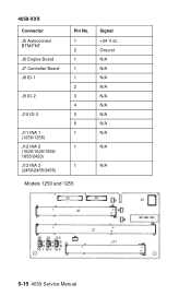
4059-XXX Connector J5 Autoconnect BTM/FNT J6 Engine Board J7 Controller Board J8 ID-1 J9 ID-2 J10 ID-3 J11 INA 1 (1250/1255) J12 INA 2 (1620/1625/1650/ 1855/2420) J13 INA 3 (2450/2455/3455) Pin No. 1 2 1 1 1 2 3 4 5 6 1 1 1 Models 1250 and 1255 Signal +24 V dc Ground N/A N/A N/A N/A N/A N/A N/A N/A N/A N/A N/A 5-15 4059 Service Manual
4059-XXX Connector J5 Autoconnect BTM/FNT J6 Engine Board J7 Controller Board J8 ID-1 J9 ID-2 J10 ID-3 J11 INA 1 (1250/1255) J12 INA 2 (1620/1625/1650/ 1855/2420) J13 INA 3 (2450/2455/3455) Pin No. 1 2 1 1 1 2 3 4 5 6 1 1 1 Models 1250 and 1255 Signal +24 V dc Ground N/A N/A N/A N/A N/A N/A N/A N/A N/A N/A N/A 5-15 4059 Service Manual

Service Manual
Page 241
Connector Locations 5-16 4059-XXX Models 1620, 1625, 1650, 1855, 2420, 2450, 2455 and 3455 • Models 1650, 1855, and 2420 do not have connector J13. • Models 1620 and 1625 have a jumper on J10 between the ... the center pin and pin 2, on J9 between the center pin and pin 4 and on J10 between the center pin and pin 5. • Models 2420, 2450 and 2455 have a jumper on J8 between the center pin and pin 2 and a jumper on J9 between the center pin and pin 3. • Model 3455...
Connector Locations 5-16 4059-XXX Models 1620, 1625, 1650, 1855, 2420, 2450, 2455 and 3455 • Models 1650, 1855, and 2420 do not have connector J13. • Models 1620 and 1625 have a jumper on J10 between the ... the center pin and pin 2, on J9 between the center pin and pin 4 and on J10 between the center pin and pin 5. • Models 2420, 2450 and 2455 have a jumper on J8 between the center pin and pin 2 and a jumper on J9 between the center pin and pin 3. • Model 3455...

Service Manual
Page 252
... Maintenance" message. The parts are available as a maintenance kit with the following part numbers: 99A0290 - 100V/750W 2450 99A0500 - 115V/750W 2420/2450/2455 99A0503 - 220V/750W 2420/2450/2455 99A0823 - 115V/750W 3455 99A0824 - 220V/750W 3455 After replacing the kit, the maintenance count must be reset... to zero to "Maintenance Page Count (2420/2450/2455/3455)" on page 3-20. 6-2 4059 Service Manual 4059-XXX Scheduled Maintenance (2420/2450/2455/3455) The operator panel displays the message "80 Scheduled Maintenance" at this interval to ...
... Maintenance" message. The parts are available as a maintenance kit with the following part numbers: 99A0290 - 100V/750W 2450 99A0500 - 115V/750W 2420/2450/2455 99A0503 - 220V/750W 2420/2450/2455 99A0823 - 115V/750W 3455 99A0824 - 220V/750W 3455 After replacing the kit, the maintenance count must be reset... to zero to "Maintenance Page Count (2420/2450/2455/3455)" on page 3-20. 6-2 4059 Service Manual 4059-XXX Scheduled Maintenance (2420/2450/2455/3455) The operator panel displays the message "80 Scheduled Maintenance" at this interval to ...