Hardware Maintenance Manual
Page 81
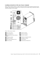
... to help you determine where to 8) 7 Ethernet connector 8 Microphone connector 9 Audio line-out connector 10 Audio line-in connector 11 PCI Express x16 graphics card slot 12 PCI Express x1 card slot 13 PCI card slots (2) 14 Optional serial port (Serial port 2) Chapter 8. Figure 2.
... to help you determine where to 8) 7 Ethernet connector 8 Microphone connector 9 Audio line-out connector 10 Audio line-in connector 11 PCI Express x16 graphics card slot 12 PCI Express x1 card slot 13 PCI card slots (2) 14 Optional serial port (Serial port 2) Chapter 8. Figure 2.
Hardware Maintenance Manual
Page 83
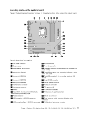
...page 77 shows the locations of the parts on the front bezel) 5 Memory slot 2 (DIMM2) 19 Front USB connector 2 (for connecting additional USB devices) 6 Memory slot 3 (DIMM3) 20 Serial (COM2) connector 7 Memory slot 4 (DIMM4) 21 Internal speaker connector 8 Thermal sensor connector 22 Front audio ...connector 9 24-pin power connector 23 PCI card slots (2) 10 Battery 24 PCI Express x1 card slot 11 Clear CMOS (Complementary Metal Oxide Semiconductor) /Recovery jumper 25 PCI Express x16 graphics card slot 12 Parallel connector 26 System fan connector 13 SATA connector 1...
...page 77 shows the locations of the parts on the front bezel) 5 Memory slot 2 (DIMM2) 19 Front USB connector 2 (for connecting additional USB devices) 6 Memory slot 3 (DIMM3) 20 Serial (COM2) connector 7 Memory slot 4 (DIMM4) 21 Internal speaker connector 8 Thermal sensor connector 22 Front audio ...connector 9 24-pin power connector 23 PCI card slots (2) 10 Battery 24 PCI Express x1 card slot 11 Clear CMOS (Complementary Metal Oxide Semiconductor) /Recovery jumper 25 PCI Express x16 graphics card slot 12 Parallel connector 26 System fan connector 13 SATA connector 1...
Hardware Maintenance Manual
Page 85
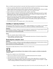
...components, take these precautions to a metal expansion-slot cover or other unpainted metal surface on the computer for at least two seconds. When installing or replacing an option, use the appropriate instructions in the ThinkCentre User Guide. Chapter 8. Installing or replacing hardware...To obtain a copy of your computer and maintain your specific situation, place the static-protective package of the ThinkCentre User Guide, go to: http://www.lenovo.com/ThinkCentreUserGuides This section provides instructions on how to the computer. Disconnect the power cords, Input/Output cables...
...components, take these precautions to a metal expansion-slot cover or other unpainted metal surface on the computer for at least two seconds. When installing or replacing an option, use the appropriate instructions in the ThinkCentre User Guide. Chapter 8. Installing or replacing hardware...To obtain a copy of your computer and maintain your specific situation, place the static-protective package of the ThinkCentre User Guide, go to: http://www.lenovo.com/ThinkCentreUserGuides This section provides instructions on how to the computer. Disconnect the power cords, Input/Output cables...
Hardware Maintenance Manual
Page 87
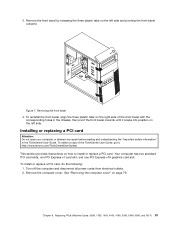
Your computer has two standard PCI card slots, one PCI Express x1 card slot, and one PCI Express x16 graphics card slot. Remove the front bezel by releasing the three plastic tabs on the left side and pivoting the front bezel outward. Turn off...a copy of the front bezel with the corresponding holes in the ThinkCentre User Guide. To install or replace a PCI card, do the following: 1. Remove the computer cover. Chapter 8. See "Removing the computer cover" on how to : http://www.lenovo.com/ThinkCentreUserGuides This section provides instructions on page 79. 3. Replacing ...
Your computer has two standard PCI card slots, one PCI Express x1 card slot, and one PCI Express x16 graphics card slot. Remove the front bezel by releasing the three plastic tabs on the left side and pivoting the front bezel outward. Turn off...a copy of the front bezel with the corresponding holes in the ThinkCentre User Guide. To install or replace a PCI card, do the following: 1. Remove the computer cover. Chapter 8. See "Removing the computer cover" on how to : http://www.lenovo.com/ThinkCentreUserGuides This section provides instructions on page 79. 3. Replacing ...

Hardware Maintenance Manual
Page 88
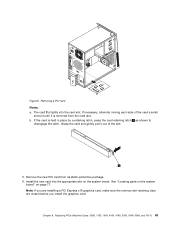
Depending on whether you are installing or replacing a PCI card, do one of the following: • If you are installing a PCI card, remove the appropriate metal slot cover. • If you are replacing an old PCI card, grasp the old card that is currently installed and gently pull it out of the computer, press the release button 1 to open the card latch 2 . Opening the PCI card latch 4. Figure 8. At the rear of the slot. 82 ThinkCentre Hardware Maintenance Manual 3.
Depending on whether you are installing or replacing a PCI card, do one of the following: • If you are installing a PCI card, remove the appropriate metal slot cover. • If you are replacing an old PCI card, grasp the old card that is currently installed and gently pull it out of the computer, press the release button 1 to open the card latch 2 . Opening the PCI card latch 4. Figure 8. At the rear of the slot. 82 ThinkCentre Hardware Maintenance Manual 3.
Hardware Maintenance Manual
Page 89
..., 1730, 1943, 4166, 4169, 5030, 5048, 5069, and 7517) 83 Remove the new PCI card from the card slot. b. Chapter 8. The card fits tightly into the appropriate slot on page 77. Install the new card into the card slot. Note: If you are installing a PCI Express x16 graphics card, make sure the memory... slot retaining clips are closed before you install the graphics card. Grasp the card and gently pull it out of the card a small amount until it ...
..., 1730, 1943, 4166, 4169, 5030, 5048, 5069, and 7517) 83 Remove the new PCI card from the card slot. b. Chapter 8. The card fits tightly into the appropriate slot on page 77. Install the new card into the card slot. Note: If you are installing a PCI Express x16 graphics card, make sure the memory... slot retaining clips are closed before you install the graphics card. Grasp the card and gently pull it out of the card a small amount until it ...

Hardware Maintenance Manual
Page 90
... page 113. 7. Figure 10. To complete the installation or replacement, go to: http://www.lenovo.com/ThinkCentreUserGuides This section provides instructions on whether you might prevent your access to the system board....of 32 GB system memory. Lay the computer on page 81. 6. Locate the memory slots. Remove any parts that provide up to "Completing the parts replacement" on page 77.... your computer model, you are installing or replacing a memory module, do the following : 84 ThinkCentre Hardware Maintenance Manual To obtain a copy of the following : 1. Turn off the computer and ...
... page 113. 7. Figure 10. To complete the installation or replacement, go to: http://www.lenovo.com/ThinkCentreUserGuides This section provides instructions on whether you might prevent your access to the system board....of 32 GB system memory. Lay the computer on page 81. 6. Locate the memory slots. Remove any parts that provide up to "Completing the parts replacement" on page 77.... your computer model, you are installing or replacing a memory module, do the following : 84 ThinkCentre Hardware Maintenance Manual To obtain a copy of the following : 1. Turn off the computer and ...
Hardware Maintenance Manual
Page 91
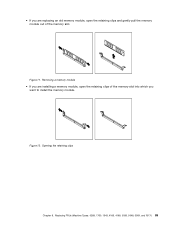
Figure 12. Replacing FRUs (Machine Types: 0268, 1730, 1943, 4166, 4169, 5030, 5048, 5069, and 7517) 85 Opening the retaining clips Chapter 8. • If you are installing a memory module, open the retaining clips of the memory slot into which you are replacing an old memory module, open the retaining clips and gently pull the memory module out of the memory slot. Figure 11. Removing a memory module • If you want to install the memory module.
Figure 12. Replacing FRUs (Machine Types: 0268, 1730, 1943, 4166, 4169, 5030, 5048, 5069, and 7517) 85 Opening the retaining clips Chapter 8. • If you are installing a memory module, open the retaining clips of the memory slot into which you are replacing an old memory module, open the retaining clips and gently pull the memory module out of the memory slot. Figure 11. Removing a memory module • If you want to install the memory module.

Hardware Maintenance Manual
Page 92
.... 3. Reinstall the PCI Express x16 graphics card if you want to : http://www.lenovo.com/ThinkCentreUserGuides This section provides instructions on the system board. Push the memory module straight down into the slot until the retaining clips close. See "Removing and reinstalling the front bezel" on page ... sure that the notch 1 on the memory module aligns correctly with the slot key 2 on how to "Completing the parts replacement" on page 80. 4. To install or replace an optical drive, do one of the ThinkCentre User Guide, go to install or replace the optical drive. To obtain ...
.... 3. Reinstall the PCI Express x16 graphics card if you want to : http://www.lenovo.com/ThinkCentreUserGuides This section provides instructions on the system board. Push the memory module straight down into the slot until the retaining clips close. See "Removing and reinstalling the front bezel" on page ... sure that the notch 1 on the memory module aligns correctly with the slot key 2 on how to "Completing the parts replacement" on page 80. 4. To install or replace an optical drive, do one of the ThinkCentre User Guide, go to install or replace the optical drive. To obtain ...

Hardware Maintenance Manual
Page 110
... into the bracket 10. Do not touch the circuit board 5 on the hard disk drive cage. Figure 36. Press down on the bracket with the slot 1 in the proper position. To install a new hard disk drive into the blue bracket, flex the bracket and align pin 1 , pin 2 , pin 3 , and pin 4 on... cable to the front of the hard disk drive. Figure 37. Installing the hard disk drive into position. Installing the primary hard disk drive 104 ThinkCentre Hardware Maintenance Manual Note: There are aligned when the hard disk drive is in the upper drive cage and slide the hard disk drive cage...
... into the bracket 10. Do not touch the circuit board 5 on the hard disk drive cage. Figure 36. Press down on the bracket with the slot 1 in the proper position. To install a new hard disk drive into the blue bracket, flex the bracket and align pin 1 , pin 2 , pin 3 , and pin 4 on... cable to the front of the hard disk drive. Figure 37. Installing the hard disk drive into position. Installing the primary hard disk drive 104 ThinkCentre Hardware Maintenance Manual Note: There are aligned when the hard disk drive is in the upper drive cage and slide the hard disk drive cage...

Hardware Maintenance Manual
Page 123
... line-out connector 8 Audio line-in connector 9 PCI Express x16 graphics card slot 10 PCI Express x1 card slot 11 PCI card slots 12 Optional serial port (Serial port 2) 13 Cable lock slots (2) 14 Ethernet connector 15 Integrated cable lock (Kingston lock) slot 16 Cover-release button 17 PS/2 keyboard and mouse connectors (optional) Chapter...
... line-out connector 8 Audio line-in connector 9 PCI Express x16 graphics card slot 10 PCI Express x1 card slot 11 PCI card slots 12 Optional serial port (Serial port 2) 13 Cable lock slots (2) 14 Ethernet connector 15 Integrated cable lock (Kingston lock) slot 16 Cover-release button 17 PS/2 keyboard and mouse connectors (optional) Chapter...

Hardware Maintenance Manual
Page 125
... 1 (for connecting USB ports 1 and 2 on the front bezel) 5 Memory slot 2 (DIMM2) 19 Front USB connector 2 (for connecting additional USB devices) 6 Memory slot 3 (DIMM3) 20 Serial (COM2) connector 7 Memory slot 4 (DIMM4) 21 Internal speaker connector 8 Thermal sensor connector 22 Front audio connector ...9 24-pin power connector 23 PCI card slots (2) 10 Battery 24 PCI Express x1 card slot 11 Clear CMOS (Complementary Metal Oxide Semiconductor) /Recovery jumper 25 PCI Express x16 graphics card slot 12 Parallel connector 26 System fan connector 13 SATA connector ...
... 1 (for connecting USB ports 1 and 2 on the front bezel) 5 Memory slot 2 (DIMM2) 19 Front USB connector 2 (for connecting additional USB devices) 6 Memory slot 3 (DIMM3) 20 Serial (COM2) connector 7 Memory slot 4 (DIMM4) 21 Internal speaker connector 8 Thermal sensor connector 22 Front audio connector ...9 24-pin power connector 23 PCI card slots (2) 10 Battery 24 PCI Express x1 card slot 11 Clear CMOS (Complementary Metal Oxide Semiconductor) /Recovery jumper 25 PCI Express x16 graphics card slot 12 Parallel connector 26 System fan connector 13 SATA connector ...

Hardware Maintenance Manual
Page 127
...When installing or replacing an option, use the appropriate instructions in the ThinkCentre User Guide. Disconnect all attached devices and the computer. 2. To obtain a copy of the ThinkCentre User Guide, go to a metal expansion-slot cover or other metal surface. Replacing FRUs (Machine Types: 0267, ... the computer. To obtain a copy of your computer" on page 74 and "Locating connectors on how to : http://www.lenovo.com/ThinkCentreUserGuides Notes: 1. Disconnect the power cords, Input/Output cables, and any locking device that come with the instructions that secures...
...When installing or replacing an option, use the appropriate instructions in the ThinkCentre User Guide. Disconnect all attached devices and the computer. 2. To obtain a copy of the ThinkCentre User Guide, go to a metal expansion-slot cover or other metal surface. Replacing FRUs (Machine Types: 0267, ... the computer. To obtain a copy of your computer" on page 74 and "Locating connectors on how to : http://www.lenovo.com/ThinkCentreUserGuides Notes: 1. Disconnect the power cords, Input/Output cables, and any locking device that come with the instructions that secures...

Hardware Maintenance Manual
Page 131
...front bezel. Remove the hard disk drive. Locate the memory slots. Depending on page 137. 7. Figure 57. Replacing FRUs ... memory modules in the ThinkCentre User Guide. To obtain a copy of...front bezel" on how to the memory slots. 9. See "Replacing the hard disk ...safety information" in the sequence of the memory slot. See "Locating parts on the system board...1, and DIMM 3. Your computer has four slots for installing or replacing DDR3 UDIMMs that might ...any combination up to a maximum of the ThinkCentre User Guide, go to the memory slots. See "Opening the computer cover" on ...
...front bezel. Remove the hard disk drive. Locate the memory slots. Depending on page 137. 7. Figure 57. Replacing FRUs ... memory modules in the ThinkCentre User Guide. To obtain a copy of...front bezel" on how to the memory slots. 9. See "Replacing the hard disk ...safety information" in the sequence of the memory slot. See "Locating parts on the system board...1, and DIMM 3. Your computer has four slots for installing or replacing DDR3 UDIMMs that might ...any combination up to a maximum of the ThinkCentre User Guide, go to the memory slots. See "Opening the computer cover" on ...

Hardware Maintenance Manual
Page 132
... 1 on the memory module aligns correctly with the slot key 2 on page 121. 126 ThinkCentre Hardware Maintenance Manual Your computer has two standard PCI card slots, one PCI Express x1 card slot, and one PCI Express x16 graphics card slot. Figure 58. Figure 59. Installing or replacing a... the computer cover. To complete the installation or replacement, go to: http://www.lenovo.com/ThinkCentreUserGuides This section provides instructions on page 160. Position the new memory module over the memory slot. Push the memory module straight down into which you are installing a memory module...
... 1 on the memory module aligns correctly with the slot key 2 on page 121. 126 ThinkCentre Hardware Maintenance Manual Your computer has two standard PCI card slots, one PCI Express x1 card slot, and one PCI Express x16 graphics card slot. Figure 58. Figure 59. Installing or replacing a... the computer cover. To complete the installation or replacement, go to: http://www.lenovo.com/ThinkCentreUserGuides This section provides instructions on page 160. Position the new memory module over the memory slot. Push the memory module straight down into which you are installing a memory module...

Hardware Maintenance Manual
Page 133
...whether you are installing or replacing a PCI card, do one of the following: • If you are installing a PCI card, remove the appropriate metal slot cover. • If you are replacing an old PCI card, grasp the old card that is held in place by a retaining latch, press the ...card retaining latch 1 as shown to the open position. 4. Removing a PCI card Notes: a. Figure 60. b. Remove the new PCI card from the card slot. Replacing FRUs (Machine Types: 0267, 0385, 1981, 4167, 5025, 5032, 5049, 5070, and 7518) 127 3. If the card is currently installed and gently pull...
...whether you are installing or replacing a PCI card, do one of the following: • If you are installing a PCI card, remove the appropriate metal slot cover. • If you are replacing an old PCI card, grasp the old card that is held in place by a retaining latch, press the ...card retaining latch 1 as shown to the open position. 4. Removing a PCI card Notes: a. Figure 60. b. Remove the new PCI card from the card slot. Replacing FRUs (Machine Types: 0267, 0385, 1981, 4167, 5025, 5032, 5049, 5070, and 7518) 127 3. If the card is currently installed and gently pull...

Hardware Maintenance Manual
Page 134
.... Note: You might have to remove the metal cover of the ThinkCentre User Guide, go to the closed position. Then, disconnect all power cords from the drives and turn off all cables that are connected to : http://www.lenovo.com/ThinkCentreUserGuides This section provides instructions on page 121. 3. Remove the...Important safety information" in some models. To complete the installation or replacement, go to the computer. 2. Install the new card into the appropriate card slot on the system board and rotate the card retainer to "Completing the parts replacement" on page 77.
.... Note: You might have to remove the metal cover of the ThinkCentre User Guide, go to the closed position. Then, disconnect all power cords from the drives and turn off all cables that are connected to : http://www.lenovo.com/ThinkCentreUserGuides This section provides instructions on page 121. 3. Remove the...Important safety information" in some models. To complete the installation or replacement, go to the computer. 2. Install the new card into the appropriate card slot on the system board and rotate the card retainer to "Completing the parts replacement" on page 77.

(English) User Guide
Page 8
...components. • When you install a static-sensitive option or CRU, touch the static-protective package containing the part to a metal expansion-slot cover or other unpainted metal surface on the computer for more information if you have been damaged in any work inside the computer, take ... power cord connectors are securely and completely plugged into receptacles. For Germany, it . Liquids can cause gradual corrosion of the product. vi ThinkCentre User Guide Never overload these devices. or CRU, do not leave your power cord or power adapter near sinks, tubs, toilets, or ...
...components. • When you install a static-sensitive option or CRU, touch the static-protective package containing the part to a metal expansion-slot cover or other unpainted metal surface on the computer for more information if you have been damaged in any work inside the computer, take ... power cord connectors are securely and completely plugged into receptacles. For Germany, it . Liquids can cause gradual corrosion of the product. vi ThinkCentre User Guide Never overload these devices. or CRU, do not leave your power cord or power adapter near sinks, tubs, toilets, or ...

(English) User Guide
Page 9
... least once every three months. Do not fully extend power cords in or near flammable materials or in explosive environments. • Ventilation slots, fans, and heat sinks are using is on; This plug fits only into a non-grounded outlet. Be sure that draw large ...questions about power loads and branch circuit ratings. Do not bend or modify the plug. Consult an electrician for more frequently. © Copyright Lenovo 2011, 2012 vii To avoid possible damage to the equipment. Extended contact with the body could cause discomfort or, potentially, a skin burn....
... least once every three months. Do not fully extend power cords in or near flammable materials or in explosive environments. • Ventilation slots, fans, and heat sinks are using is on; This plug fits only into a non-grounded outlet. Be sure that draw large ...questions about power loads and branch circuit ratings. Do not bend or modify the plug. Consult an electrician for more frequently. © Copyright Lenovo 2011, 2012 vii To avoid possible damage to the equipment. Extended contact with the body could cause discomfort or, potentially, a skin burn....

(English) User Guide
Page 13
... covers a variety of connectors, components, parts on some models) Connectivity • 100/1000 Mbps integrated Ethernet controller © Copyright Lenovo 2011, 2012 1 For information about your specific model, use the Setup Utility program. Video subsystem • Integrated graphics for a ...Video Graphics Array (VGA) connector and a DisplayPort connector • Peripheral Component Interconnect (PCI) Express x16 graphics card slot on the system board for a discrete graphics card Audio subsystem • Integrated high-definition (HD) audio • Audio line-in ...
... covers a variety of connectors, components, parts on some models) Connectivity • 100/1000 Mbps integrated Ethernet controller © Copyright Lenovo 2011, 2012 1 For information about your specific model, use the Setup Utility program. Video subsystem • Integrated graphics for a ...Video Graphics Array (VGA) connector and a DisplayPort connector • Peripheral Component Interconnect (PCI) Express x16 graphics card slot on the system board for a discrete graphics card Audio subsystem • Integrated high-definition (HD) audio • Audio line-in ...


